Table of Contents
Advertisement
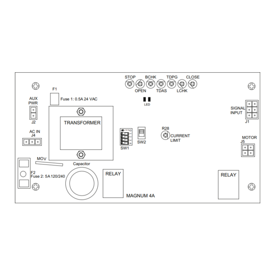
F1
AUX
Fuse 1: 0.5A 24 VAC
PWR
J2
TRANSFORMER
AC IN
J4
MOV
F2
Fuse 2: 5A 120/240
DN 0557
• Turn OFF all power to the Automatic Door if a Safety System is not working.
• Instruct the Owner to keep all power turned OFF until corrective action can be achieved by a NABCO
trained technician. Failure to follow these practices may result in serious consequences.
• NEVER leave a Door operating without all Safety detection systems operational.
Swing Door Operator
Wiring and Adjustment Manual
** with Magnum 4A Control*
SW1
Capacitor
RELAY
STOP
BCHK
TDPG
OPEN
TDAS
LED
R28
CURRENT
LIMIT
SW2
MAGNUM 4A
WARNING
S82 W18717 Gemini Drive
Muskego, Wisconsin 53150
Phone: (877) 622-2694
Fax: (888) 679-3319
www.nabcoentrances.com
Technical Support: (866) 622-8325
CLOSE
LCHK
RELAY
SIGNAL
INPUT
J1
MOTOR
J5
Part #C-00084
Rev. 9/09/16
Advertisement
Table of Contents

Related Manuals for Nabco GT-300

Summary of Contents for Nabco GT-300
- Page 1 • Turn OFF all power to the Automatic Door if a Safety System is not working. • Instruct the Owner to keep all power turned OFF until corrective action can be achieved by a NABCO trained technician. Failure to follow these practices may result in serious consequences.
-
Page 2: Table Of Contents
Section 7b. GT-300-400-500 (Simultaneous Pair) ........ -
Page 3: Warning Labels
Magnum 4A Control Wiring and Adjustment Manual www.NabcoEntrances.com Part #C-00084 Rev. 9-09-16 WARNING LABELS Warning labels are universal and used to alert an individual of potential harm to one’s self or to others. The following warning labels are listed in a hierarchy order that defines the most potential danger first, and the least potential danger last. Please refer to this page in the event that a warning label is displayed within this manual and further definition needs to be explained. -
Page 4: General Safety Recommendations
www.NabcoEntrances.com Magnum 4A Control Wiring and Adjustment Manual Rev. 9-09-16 Part #C-00084 GENERAL SAFETY RECOMMENDATIONS Read, study and understand general safety recommendations, warning labels, installation WARNING and operating instructions contained in, or referenced in this manual before operating. If you do not understand the instruction, ask a qualified technician. -
Page 5: Chapter 1: Scope
Use them in addition to the ANSI standards. The owner should determine the door is operating properly and should immediately call for service if there is any malfunction. All installation changes and adjustments must be made by qualified, NABCO trained technicians. -
Page 6: Chapter 2: Getting Started
All Wiring Diagrams included within this manual, reflect typical primary and secondary circuits that might be commonly used. Onsite wiring may be different from that shown. Note: NABCO factory utilizes Underwriters Laboratories (UL) recognized component wire, terminals and connector housings to manufacture Opus 10 Swing Door systems. -
Page 7: Section 2C. Output Power Guidelines
► If TOTAL current draw exceeds 500 mA (0.5 amps) the installer must utilize an auxiliary power supply such as the NABCO Transformer 24 VAC, P/N 14-2101. The Opus 10 Control must Not be used to output power to: CAUTION ►... -
Page 8: Chapter 3: Magnum 4A Board Terminals
www.NabcoEntrances.com Magnum 4A Control Wiring and Adjustment Manual Rev. 9-09-16 Part #C-00084 CHAPTER 3: Magnum 4A Board Terminals The Magnum 4A Control is used to power and control operating characteristics of the door. This is done through the use of harnesses that are connected to terminals located on the Magnum 4A Control Board, plus wiring that is connected to other components within the Header. -
Page 9: Section 3B. Power Harness
Magnum 4A Control Wiring and Adjustment Manual www.NabcoEntrances.com Part #C-00084 Rev. 9-09-16 Table #-1 Terminal Block Connections Brown Aux Pwr 24 VAC Neutral X Circuit is used for any Sensor that operates on 24 VAC. Pole Wire Harness Circuit Description X Sensor must not exceed 0.5 amp current draw. Orange 24 VAC Hot X If Sensor exceeds 0.5 amp current draw Fuse (F1) will trip. -
Page 10: Section 3C. Motor Harness (300/400/500)
www.NabcoEntrances.com Magnum 4A Control Wiring and Adjustment Manual Rev. 9-09-16 Part #C-00084 Section 3c. Motor Harness (300/400/500) Motor Brake Module STOP BCHK TDPG CLOSE OPEN TDAS LCHK Fuse 1: 0.5A 24 VAC SIGNAL INPUT Motor Leads TRANSFORMER AC IN CURRENT LIMIT MOTOR Capacitor RELAY RELAY... -
Page 11: Chapter 4: Adjustments And Status Leds
Magnum 4A Control Wiring and Adjustment Manual www.NabcoEntrances.com Part #C-00084 Rev. 9-09-16 CHAPTER 4: Adjustments and Status LEDs Do Not touch other parts of the Magnum 4A Control board with a screwdriver or CAUTION anything else metal. Damage to electrical circuitry may occur. Section 4a. Swing Door Positions Figure 4-1 Door Positions Closed... - Page 12 www.NabcoEntrances.com Magnum 4A Control Wiring and Adjustment Manual Rev. 9-09-16 Part #C-00084 SWITCHES SHOWN IN “ON” POSITION Not Used OFF: Closed Loop Safety / ON: Open Loop Safety OFF: Push-N-Go active / ON: Push-N-Go Inactive OFF: Sequential Mode / ON: Timer Mode Figure 4-3 Dip Switch (Displayed in ON position) DN 0561...
- Page 13 Magnum 4A Control Wiring and Adjustment Manual www.NabcoEntrances.com Part #C-00084 Rev. 9-09-16 Recommended settings correspond with positions on a clock with 12 o’clock at the top as the starting point. Potentiometer settings might need to be adjusted accordingly. After each adjustment, wait at least 5 seconds before testing.
- Page 14 www.NabcoEntrances.com Magnum 4A Control Wiring and Adjustment Manual Rev. 9-09-16 Part #C-00084 TDAS Determines how long door will stay open after activation (or input signal) is released. Potentiometer Description Used when door is in Timer Mode (Dip Switch #4). (Time Delay Activating Signal) Note: The time delay does not begin counting until after loss of activation and door has Full Automatic door reached Back Check.
-
Page 15: Section 4C. Status Leds
Magnum 4A Control Wiring and Adjustment Manual www.NabcoEntrances.com Part #C-00084 Rev. 9-09-16 Potentiometer Description Current Limit Recycle sensitivity needs Recommended setting fully clockwise position Event Action adjusting. until all other adjustments are made. When recycle is triggered, door will stop and coast to a close. -
Page 16: Chapter 5: Connect Incoming 120 Vac Wires
www.NabcoEntrances.com Magnum 4A Control Wiring and Adjustment Manual Rev. 9-09-16 Part #C-00084 CHAPTER 5: Connect Incoming 120 VAC Wires Disconnect 120 VAC power prior to making any electrical connections. Failure to DANGER do so may result in serious personal or fatal injury. When uncertain whether power supply is disconnected, always verify using a voltmeter. -
Page 17: Chapter 6: Wiring Safety Devices
Magnum 4A Control Wiring and Adjustment Manual www.NabcoEntrances.com Part #C-00084 Rev. 9-09-16 CHAPTER 6: Wiring Safety Devices Do Not touch other parts of the Magnum 4A Control board with a screwdriver or CAUTION anything else metal. Damage to electrical circuitry may occur. Note: If an Inswing Operator must be equipped for panic breakout, a panic breakout switch must be used to turn off the automatic operator when the door is broken out. -
Page 18: Section 6B. Panic Breakout Latch/Switch (Closed Loop Continuous Safety Circuit)
www.NabcoEntrances.com Magnum 4A Control Wiring and Adjustment Manual Rev. 9-09-16 Part #C-00084 USE THESE CONNECTIONS ON INSWING DOORS WITH PANIC BREAKOUT Panic Latch must be flipped. Arrow marked "EXT" must point to the Interior of Black building. ( Contacts must close when door is broken out) Panic Latch Kit Part # 11- 0941... - Page 19 Magnum 4A Control Wiring and Adjustment Manual www.NabcoEntrances.com Part #C-00084 Rev. 9-09-16 The Panic Latch Switch is used to prevent activation when the door is broken out in a normally closed circuit (when safety is fail-safe). When the door is broken out, the Panic Breakout Limit Switch will OPEN the circuit to activate the Continuous Safety feature and disable the Operator.
-
Page 20: Chapter 7: Wiring Diagrams (General)
Magnum 4A Control Wiring and Adjustment Manual Rev. 9-09-16 Part #C-00084 CHAPTER 7: Wiring Diagrams (General) Section 7a. GT-300-400-500 Single Door Wiring Diagrams (General) 7-19... -
Page 21: Section 7B. Gt-300-400-500 (Simultaneous Pair)
Magnum 4A Control Wiring and Adjustment Manual www.NabcoEntrances.com Part #C-00084 Rev. 9-09-16 Section 7b. GT-300-400-500 (Simultaneous Pair) 7-20 Wiring Diagrams (General) -
Page 22: Section 7C. Gt-300-400-500 (Simultaneous Pair W/One Magnum 4A Control)
Magnum 4A Control Wiring and Adjustment Manual Rev. 9-09-16 Part #C-00084 Section 7c. GT-300-400-500 (Simultaneous Pair w/One Magnum 4A Control) Wiring Diagrams (General) 7-21... -
Page 23: Section 7D. Gt-710-8310-8710 Single Door
Magnum 4A Control Wiring and Adjustment Manual www.NabcoEntrances.com Part #C-00084 Rev. 9-09-16 Section 7d. GT-710-8310-8710 Single Door 7-22 Wiring Diagrams (General) -
Page 24: Section 7E. Gt-710-8310-8710 (Simultaneous Pair)
www.NabcoEntrances.com Magnum 4A Control Wiring and Adjustment Manual Rev. 9-09-16 Part #C-00084 Section 7e. GT-710-8310-8710 (Simultaneous Pair) Wiring Diagrams (General) 7-23... -
Page 25: Section 7F. Gt-710-8310-8710 (Simultaneous Pair W/One Magnum 4A Control)
Magnum 4A Control Wiring and Adjustment Manual www.NabcoEntrances.com Part #C-00084 Rev. 9-09-16 Section 7f. GT-710-8310-8710 (Simultaneous Pair w/One Magnum 4A Control) 7-24 Wiring Diagrams (General) -
Page 26: Section 7G. Gt-1400 Single Fold With One Magnum 4A Control
www.NabcoEntrances.com Magnum 4A Control Wiring and Adjustment Manual Rev. 9-09-16 Part #C-00084 Section 7g. GT-1400 Single Fold with One Magnum 4A Control Wiring Diagrams (General) 7-25... -
Page 27: Section 7H. Gt-1400 Bi-Fold With Two Magnum 4A Controls
Magnum 4A Control Wiring and Adjustment Manual www.NabcoEntrances.com Part #C-00084 Rev. 9-09-16 Section 7h. GT-1400 Bi-Fold with Two Magnum 4A Controls 7-26 Wiring Diagrams (General) -
Page 28: Section 7I. Gt-1400 Bi-Fold With One Magnum 4A Control
www.NabcoEntrances.com Magnum 4A Control Wiring and Adjustment Manual Rev. 9-09-16 Part #C-00084 Section 7i. GT-1400 Bi-Fold with One Magnum 4A Control Wiring Diagrams (General) 7-27... -
Page 29: Chapter 8: Wiring Diagrams (Accessories)
Magnum 4A Control Wiring and Adjustment Manual www.NabcoEntrances.com Part #C-00084 Rev. 9-09-16 CHAPTER 8: Wiring Diagrams (Accessories) Section 8a. Transformer Installation and Wiring for 240 Volts 8-28 Wiring Diagrams (Accessories) -
Page 30: Chapter 9: Troubleshooting
Motor circuit may be open. 1.►Go to J5 Motor Feed. 2.►Check connections on Pin (1) and Pin (2). Latch Check may be set too high. X GT-300/400/500: 1.►Go to LCHK Potentiometer. 2.►Turn counterclockwise to decrease speed. X GT-710: 1.►Adjust latch check speed on hydraulic closer. - Page 31 GT-710: Building stack pressure Upgrade Operator Unit to GT-500 or install power is excessive. close module. X GT-300/400/500: Kit Part Number: 11-13140. X GT-710 Swinger: Kit Part Number: 11-13141. Note: Please refer to section C-1 in Price Binder for more information.
- Page 32 www.NabcoEntrances.com Magnum 4A Control Wiring and Adjustment Manual Rev. 9-09-16 Part #C-00084 Safety Sensor does No power to sensor. Check wiring on harness and power to sensor. Trouble Possible Cause Action not function. Sensor may not be properly 1.►Go to Terminal Block. connected to Terminal Block.