Table of Contents
Advertisement
Advertisement
Table of Contents

Related Manuals for Wolf ComfortLine Series


Summary of Contents for Wolf ComfortLine Series
- Page 1 Installation and maintenance instructions ComfortLine FunctionLine Steel boilers up to 63 kW Wolf GmbH · Postfach 1380 · 84048 Mainburg · Tel. +49 8751/74-0 · Fax +49 8751/741600 · Internet: www.wolf-heiztechnik.de 12/03 TV Part.-No. 30 60 917 Subject to modifications...
-
Page 2: Table Of Contents
Index Index ..........................Page Reference symbols / Safety instructions .................... 3 Standards / Regulations ........................4-5 ComfortLine steel boilers ........................6 FunctionLine steel boilers ........................7 Installation ............................8-9 Boiler installation on a plinth ......................10 Boiler installation on a horizontal DHW cylinder ................11 Boiler assembly .......................... -
Page 3: Reference Symbols / Safety Instructions
Any faults and damage which may impact on safety which might limit the safe use of the equipment must be remedied immediately by a qualified contractor. • Only replace faulty components or equipment with original WOLF spare parts. -
Page 4: Standards / Regulations
DIN 4701 Rules for calculating the heat demand of buildings Only recognised heating contractors may install WOLF boilers. This heating contractor will also DIN 4751 Part 3 - Safety Equipment be responsible for the proper installation and for heating systems with flow the commissioning of the heating system. - Page 5 Standards / Regulations Steel boilers according to DIN EN 303 as well as in accordance with EC Directive 90/396/EEC (gas consuming equipment), 73/23/EEC (Low Voltage Directive), 89/336/EEC (EMC Directive), 92/42/EEC (Efficiency of Hot Water Boilers) and 93/68/EEC (Identification Directive) for heating systems with heating circuit pumps and flow temperatures up to 110 °C and 3 bar permissible operating pressure in accordance with DIN 4751 and DHW cylinder pressure (max.
-
Page 6: Comfortline Steel Boilers
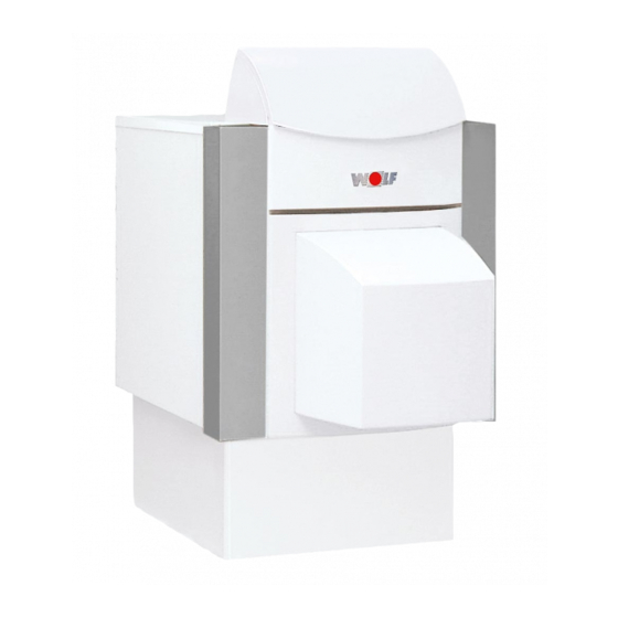
ComfortLine steel boilers Oil and gas-fired steel boiler, type CNK Oil and gas-fired steel boiler, type CNK-CB (boiler plinth, accessory) incl. DHW cylinder Oil and gas-fired steel boiler, type CNU Oil-fired steel Unit boiler, type CNU-CB incl. pressure jet oil burner incl. -
Page 7: Functionline Steel Boilers
FunctionLine steel boilers Oil and gas-fired steel boilers, type FNK Oil and gas-fired steel boiler, type FNK-FB/FE (boiler plinth, accessory) incl. DHW cylinder Oil-fired steel Unit boiler, type FNU Oil-fired steel Unit boiler, type FNU-FB/FE incl. pressure jet oil burner incl. -
Page 8: Installation
Installation The ventilation air supply must be General tips regarding location ensured and comply with local regulations or those relating to • Install the boiler with or without the DHW gas installations. We recommend cylinder on a level surface which is substantial that you supply the boiler with enough to carry its weight. -
Page 9: Installation
Installation Recommended minimum wall clearance Maintain a minimum clearance between the 1000 boiler sides and walls of 400 mm to enable the boiler door with fitted burner to be opened. Ensure that sufficient space is available for cleaning and maintenance. Recommended minimum wall clearance Transportation into the boiler room To ease the transportation into the boiler... -
Page 10: Boiler Installation On A Plinth
Boiler installation on a plinth Boiler Control unit housing Thermal insulation, boiler Casing cover Thermal insulation, boiler back Spring shackles Thermal insulation, boiler front Front casing Side casing Type plate Control unit bracket Wolf logo Boiler door Plinth (accessory) Back wall casing... -
Page 11: Boiler Installation On A Horizontal Dhw Cylinder
Boiler installation on a horizontal DHW cylinder Boiler Control unit housing Thermal insulation, boiler Casing cover Thermal insulation, boiler back Spring shackles Thermal insulation, boiler front Front casing Side casing Type plate Control unit bracket Wolf logo Boiler door Horizontal DHW cylinder Back wall casing... -
Page 12: Boiler Assembly
Boiler assembly Boiler Screws for securing the boiler • Install the plinth or the DHW cylinder in accordance with the enclosed installation instructions. • Position the boiler with adjustable bolts fully inserted using the lifting slings on the fully assembled plinth or DHW cylinder. - Page 13 Boiler assembly Insert the side casing into the boiler front pushing the spring shackles behind the boiler bracket Spring shackle Bracket Side casing installation and fit the lower folded edge into both notches (view X). Lower folded edge View X of the side casing Boiler notch Side casing installation...
- Page 14 Boiler assembly Door Fit the boiler door with the four M10x45 screws and hinge pin washers supplied. Insert the door hinge pins into the door bracket on the l.h. or r.h. side, subject to door opening. M10x45 screws Boiler door installation Back wall notches Hook the back wall casing with tabs into the notches in the side...
- Page 15 , until they click into place. shackles Front casing installation Affix the type plate Wolf logo in a clearly visible position. Clip the Wolf logo into the front casing (only for FunctionLine). Type plate Type plate / Wolf logo...
-
Page 16: Comfortline Decorative Panel Installation
ComfortLine decorative panel installation In addition, all ComfortLine boilers require the following work to be undertaken. Decorative panel Position the decorative panel with the document wallet on the holes and push against the front casing, until the clips click into place. Decorative panel installation Decorative frame (CNK 17-60 single boiler) - Page 17 ComfortLine decorative panel installation Decorative frame (CNU 17-32 Unit boiler) With the dome at the top, push the silencer hood into the decorative frame, then secure the Silencer hood silencer hood with four self-tapping screws from the inside to the decorative frame. Self-tapping screws Decorative frame...
-
Page 18: Functionline Decorative Panel Installation
FunctionLine decorative panel installation For models FNU-TH/17/20/25, the following additional work should be undertaken. Decorative panel Click the plastic clips (4 no., grey) into the front casing. Decorative panel Decorative panel installation... -
Page 19: Flue Pipe Installation
Flue pipe installation • The flue pipe cross-section must match that of the boiler flue outlet. • Reducing the flue pipe size is only permitted, if the satisfactory function has been verified (by calculation) in accordance with DIN 4705. Keep the flue pipe as short as possible and inclined towards the chimney stack. -
Page 20: Central Heating Boiler Connections
Central heating boiler connections Connect the heating flow and return to the Provide system separation by means respective boiler fittings. For connections, see of a heat exchanger, when using below. pipes which are not impermeable Install a check valve downstream of the boiler to oxygen. -
Page 21: Dhw Cylinder To Boiler Pipework
DHW cylinder to boiler pipework Install the pipework between the boiler and the DHW cylinder in accordance with the illustration below. Note The DHW cylinder loading pump must supply from the top to bottom. Close any boiler flow and return connections which are not required with caps and gaskets supplied. -
Page 22: Filling The Heating System
Filling the heating system Fill the system and vent it properly to safeguard Connection for venting the perfect boiler function. and safety flow Before connecting the boiler to the Note heating system, flush the entire system to remove residues such as welding pearls, hemp, putty, etc. - Page 23 Filling the heating system • Observe the pressure gauge of the safety equipment assembly when filling the system with water. Pressure gauge Safety assembly pressure gauge • For boilers with DHW cylinder, vent the heating coil at a system pressure of approximately 0.50 bar or less by starting the DHW cylinder loading pump (operating time approximately 2 minutes).
-
Page 24: Draining The Heating System
Draining the heating system • Switch OFF the heating system (see operating Connection for venting instructions) and let it cool down to a and safety flow maximum of 40 °C, to prevent the risk of scalding. • Open the drain tap on the boiler. •... -
Page 25: Pressure Jet Oil Burner Installation / Electrical Supply
Pressure jet oil burner installation / Electrical supply Pressure jet oil burner installation The Unit pressure jet oil burner installation instructions are included in the burner packaging. Only use bolts when securing the burner to the boiler flange, whose thread penetrates the boiler flange by a maximum of 15 mm. -
Page 26: Initial Start-Up
Initial start-up Only qualified personnel may Saving energy carry out the commissioning and • Instruct the customer about energy-savings operation of the boiler and the options. instruction of the user. • Use this opportunity for reducing the heating • Check the boiler and system for leaks. temperature night operation using control Close the water outlet - risk of overheating accessories. -
Page 27: Commissioning Report
Commissioning report Test values and Commissioning steps confirmation 1.) Water connections checked for leaks? 2.) Vented boiler and system? 3.) System pressure 1 - 2.5 bar? 4.) Function test carried out? 5.) Flue gas test: Gross flue gas temperature [°C] Ventilation air temperature [°C] Net flue gas temperature... -
Page 28: Maintenance
Maintenance Note: To ensure the reliable and safe function of a heating system, users are required to have it checked and cleaned on an annual basis by an approved heating contractor (check local regulations). Switch OFF the boiler when cleaning the boiler room. We would recommend a maintenance contract. - Page 29 Maintenance • Open the boiler door. Turbulator • Pull out the turbulators (only for CNK-40/ FNK-40 and CNK-63/FNK-63). Turbulators • Pull out the hot combustion chamber. Hot combustion chamber • Remove soot/sulphur deposits with the cleaning brush supplied. Cleaning using the cleaning brush •...
-
Page 30: Maintenance Log
Maintenance log • Please tick the maintenance steps carried out and enter the test values into this log. Maintenance steps Date Date 1. Cleaned the boiler? 2. Leak test carried out during operation? 3. Function test carried out? 4. Flue gas test: Gross flue gas temperature [°C] [°C]... -
Page 31: Maintenance Log
Maintenance log Date Date Date Date [°C] [°C] [°C] [°C] [°C] [°C] [°C] [°C] ) [°C] ) [°C] ) [°C] ) [°C]... -
Page 32: Specification
Specification CNK / FNK / CNU-Premio / CNU-TH / FNU-TH CNK-CB / FNK-FB / CNU-Premio-CB 17/155 20/155 25/155 CNU-TH-CB / FNU-TH-FB FNK-FE / FNU-TH-FE 17/155 20/155 25/155 Output range without burner 14-17 17-20 20-25 incl. Premio burner 14-17 17-20 20-25 incl. - Page 33 25/200 32/155 32/200 40/200 50/200 63/200 25/200 32/155 32/200 40/200 20-25 28-32 28-32 32-40 40-50 50-63 20-25 28-32 28-32 32-40 40-50 50-60 20-25 28-32 28-32 32-40 40-48 50-63 155/150 1225 1225 150/170 190/200 190/200 170/185 170/190 165/180 34/42 47/54 47/54 54/68 68/85 85/107...
-
Page 34: Dimensions
Dimensions CNK / FNK / CNU-Premio CNU-TH / FNU-TH Boiler height A mm Width B mm Length C mm 1056 1056 Plinth height D mm Overall height incl. control unit E mm 1115 1115 1115 1115 1115 1290 1290 Silencer hood depth Burner hood depth Draining, filling G mm... - Page 35 Dimensions CNK-CB / FNK-FB / CNU-Premio-CB CNU-TH-CB / FNU-TH-FB FNK-FE / FNU-TH-FE Boiler height A mm Width B mm Length of 155 l DHW cylinder C mm Length of 200 l DHW cylinder C mm 1262 1262 1262 1262 1262 DHW cylinder height D mm Overall height incl.
-
Page 36: Troubleshooting
Troubleshooting Fault Cause Remedy Burner does not start No voltage present Fuse, electrical connections, or enters a fault state Check the position of the ON/OFF switch at the control unit and heating sys. emergency stop switch. Oil tank empty / Fill oil tank / Gas supply line shut off open gas supply line.