
Related Manuals for Pentair Pentek PSD15


Summary of Contents for Pentair Pentek PSD15
- Page 1 PENTEK SOLAR DRIVE PSD15 INSTALLATION AND OPERATION MANUAL pentair.com P1061 (03-06-19)
-
Page 2: Table Of Contents
Pentair Pentek Solar Drive Hardware ............7 Pentair Pentek Solar Drive Overview ............8 Pentair Pentek Solar Drive Wiring Instructions ...........9 Pentair Pentek Solar Drive DIP Switch Settings ........10 Pentair Pentek Solar Drive Sensor Settings ..........11 Pentair Pentek Solar Drive Operation ............12-13 Installation Notes &... -
Page 3: Safety Instructions
This is the safety alert symbol. When you see this Pentair Pentek Solar Drive, install the Drive on an symbol on your Pentair Pentek Solar Drive or in this independent branch circuit protected by a circuit manual, look for one of the following signal words breaker, with no other appliances on the circuit. -
Page 4: Pentair Pentek Solar Drive At A Glance
Pentair Pentek Solar Drive at a Glance The Pentair Pentek Solar Drive PSD15 is an off-grid solar controller that can operate any approved Pentair Pentek submersible motor loads or operate approved alternative 3-phase alternating current (AC) motor loads up to 1.5HP from solar photovoltaic (PV) power. -
Page 5: Pentair Pentek Solar Drive Specifications
Pentair Pentek Solar Drive Specifications Input Specification: - Minimum Operating Voltage : 100 Vdc (for 115 Vac) 150 Vdc (for 230 Vac) - Maximum Solar Open Circuit Voltage: 400 Vdc - Maximum Solar PV Current in Series: 9 Amps - Earth-ground connected to chassis... -
Page 6: Pentair Pentek Solar Drive Installation Requirements
Figure 3, below. Once the Pentair Pentek Solar Drive is installed in a shaded location (see Figure 3), it can be wired to DC (solar) sources. Maximum cable lengths for 115 and 230Vac for different motor load currents are shown in Figure 2 below. -
Page 7: Pentair Pentek Solar Drive Hardware
There is direct access to the power and signal terminals on the circuit board once the enclosure door is removed. The Pentair Pentek Solar Drive controller should be mounted on a wall or other vertical surface using the back bracket (see Figure 5 below). On the back side of the unit there are two set screws used to hang the unit on the back bracket. -
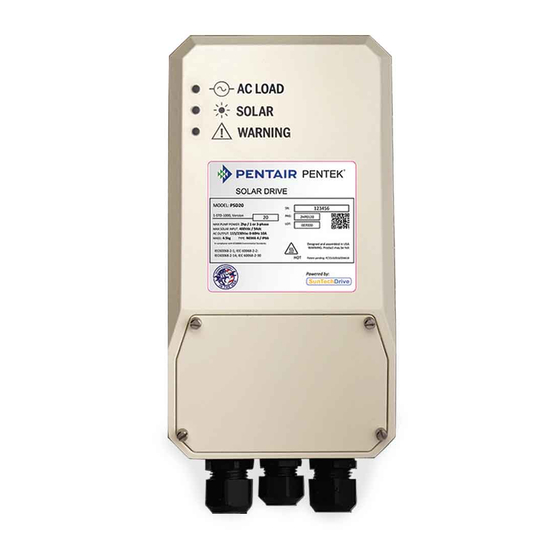
Page 8: Pentair Pentek Solar Drive Overview
Pentair Pentek Solar Drive Overview The features of the Pentair Pentek Solar Drive controller are shown in Figure 6. Three LEDs are used to indicate the Pentair Pentek Solar Drive controller's operation (more details provided on page 10). Once the door of the enclosure is open, there are three terminal blocks:... -
Page 9: Pentair Pentek Solar Drive Wiring Instructions
Do not ground the positive or negative leads of the PV modules! Only ground the mounting frames of the PV modules. Never run the Pentair Pentek Solar Drive controller when the AC pump is not connected! It might cause damage to the controller. -
Page 10: Pentair Pentek Solar Drive Dip Switch Settings
The Pentair Pentek Solar Drive controller can operate most AC motors up to the power limits of the controller: 50 or 60Hz; 120Vac or 230Vac. In order for the Pentair Pentek Solar Drive to match the motor specifications, the first three DIP switches on the left are used for motor selection. -
Page 11: Pentair Pentek Solar Drive Sensor Settings
Pentair Pentek Solar Drive Sensor Settings The Pentair Pentek Solar Drive controller can be turned ON or OFF remotely by using a digital input or by using a standard float switch. There is a float switch terminal block (Figure 6 on page 8) where digital signal wires are connected. -
Page 12: Pentair Pentek Solar Drive Operation
Pentair Pentek Solar Drive Operation Once the Pentair Pentek Solar Drive controller is wired to the solar source and a motor load, and the DIP switches settings are configured to match the motor specification, then the Pentair Pentek Solar Drive is ready for operation. -
Page 13: Pentair Pentek Solar Drive Operation
Pentair Pentek Solar Drive will stop its operation, and the WARNING LED will blink red. The WARNING LED will be solid red if the temperature of the Pentair Pentek Solar Drive rises above 80°C (176˚), at which point the Pentair Pentek Solar Drive will stop operating and wait until the temperature drops. -
Page 14: Installation Notes & Maintenance
No. of Solar PV Panels in Series: ___________________________________________________ Note to Installer: Record the data listed above along with DIP switch setting for future reference. Give manual to end user or attach to Pentair Pentek Solar Drive when installation is complete. -
Page 15: Troubleshooting - Indicator Lights
Troubleshooting - Indicator Lights There are three LED lights on the Pentair Pentek Solar Drive. The indicator lights and their definitions are listed below. AC POWER SOLAR WARNING MODE (Green) (Yellow) (Red) - Unit is OFF FLASHING - Startup - Running... -
Page 16: Warranty
*For a detailed list of where Pentair trademarks are registered, please visit www.pentair.com/en/registrations.html. Pentair trademarks and logos are owned by Pentair PLC. or its affiliates. Third party registered and unregistered trademarks and logos are the property of their respective owners. Because we are continuously improving our products and services, Pentair reserves the right to change specifications without prior notice.