Telex Audiocom WM1000 User Instructions
Wall mount intercom stations
Hide thumbs
Also See for Audiocom WM1000:
- User instructions (10 pages) ,
- Addendum (1 page) ,
- User instructions (24 pages)

Related Manuals for Telex Audiocom WM1000


Summary of Contents for Telex Audiocom WM1000
- Page 1 ® T elex User Instructions 2 0 0 WM2000 Shown Model WM1000 / WM2000 Wall Mount Intercom Stations ® Audiocom Intercom Systems ®...
- Page 2 This product meets Electromagnetic Compatibility Directive 89/336/EEC. Introduction. Thank you for purchasing the Audiocom WM1000 / WM2000 Wall Mount In- tercom Station. We hope the many design features of this product will satisfy your intercommunication requirements for many years to come. To get the most out of your new intercom station, please take a few moments to look through this booklet before using the Intercom Station for the first time.
-
Page 3: Table Of Contents
Table of Contents Description Features . Installation Unpacking Configuration Switch Pre-check . Intercom Channel Connections Dynamic-Mic Headset Connection Power-Up Sidetone Adjustment Operation Channel Select (WM2000 Only) . Receiving Calls Calling an Intercom Channel Specifications Factory Service and Parts Information... -
Page 4: Description
Aud iocom ® Description The WM1000 and WM2000 Intercom Stations are designed for stationary, wall- mounted installation in standard two-gang electrical boxes. The WM1000 is a single-channel station; the WM2000 provides switch-selectable access to either of two intercom channels. The WM1000 and WM2000 are ideal when users need to ac- cess the intercom system from strategic locations where a desktop station would be unsuitable, but they do not wish to carry around a belt-pack station. -
Page 5: Features
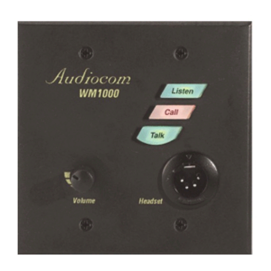
Features Channel Select Switch (WM2000 Only): Used to switch between intercom chan- nels one and two. The switch lights green for channel one and red for channel two. Intercom Listen Key: Both momentary (push-to-listen) and latching (hands-free listen) are possible. Call Key: Used to send call signals on the intercom channel and to indicate in- coming calls. -
Page 6: Installation
Each WM1000 / WM2000 is supplied with the following items. Contact the shipper or your Audiocom dealer immediately if anything is damaged or missing. Detach and fill out the registration card and return it to Telex to properly register your intercom station. -
Page 7: Intercom Channel Connections
Table 1. Configuration Switch Settings Switch Description Settings Default Number Open=Off; Closed=On Setting Not used Don't care Open Closed: DC Call signal method Open Open: Audiocom Closed: Disabled Incoming call beep Open Open: Enabled Closed: Unbalanced Microphone type Open Open: Balanced Not used Don’t care Open... - Page 8 Aud iocom ® General Information After connecting intercom stations as described below, and before installing the mounting screws, connect a headset and perform the sidetone adjustment as de- scribed on page 10. The WM1000 and WM2000 mount in a standard two-gang electrical box. Some ex- ample intercom system configurations are shown in Figures through 5, pages through 14.
-
Page 9: Dynamic-Mic Headset Connection
Method 2: Locally Powered Connection Using this method, the intercom station is connected to the intercom line just like any phantom-powered intercom station, except that a local power supply is also con- nected. This local power supply is located right with the intercom station and pro- vides power for that station only. -
Page 10: Power-Up
Aud iocom ® Power-Up Make sure any local power supplies are plugged in, and turn on the power switches of any phantom power supplies. If you are using a large number of locally powered intercom stations, you should activate their local power supplies before activating any phantom power supply. Otherwise, you may get an overload indication on the phantom supply. - Page 11 6. Install the intercom station mounting screws after completing the adjustments. The station is now ready for use. If you are using headphones that completely enclose the ears, adjust sidetone as follows: 1. Activate channel 1 as described in the operating instructions. (Required only for the WM2000, the WM1000 is active on whichever channel it is connected to.) 2.
- Page 12 Aud iocom ® 500 METERS Audiocom Audiocom Audiocom Listen Listen Listen WM1000 WM2000 WM2000 Call Call Call GRN 1 GRN 1 Talk Ch Select Talk Ch Select Talk RED 2 RED 2 Volume Headset Volume Headset Volume Headset WM1000 WM2000 WM2000 LOCAL POWER 12 to 15 VDC, 65 to 150 mA...
- Page 13 Audiocom Audiocom Audiocom Listen Listen Listen WM2000 WM2000 WM2000 GRN 1 GRN 1 GRN 1 Ch Select Talk Ch Select Talk Ch Select Talk RED 2 RED 2 RED 2 Volume Volume Volume Headset Headset Headset WM2000 WM2000 WM2000 WM2000 WM2000 WM1000 Audiocom...
- Page 14 Aud iocom ® Audiocom Audiocom Audiocom Listen Listen Listen WM1000 WM2000 WM2000 Call Call Call Talk GRN 1 GRN 1 Ch Select Talk Ch Select Talk RED 2 RED 2 Volume Headset Volume Headset Volume Headset WM1000 WM2000 WM2000 LOCAL POWER LOCAL POWER LOCAL POWER 12 to 15 VDC, 65 to 150 mA...
- Page 15 TO ADDITIONAL TO POWER SINGLE-CHANNEL STATIONS SUPPLY CONNECTOR Channel Audio high / Power Pair 1 Channel Audio low / Power DC Common Pair 2 Shield* Shield* PIN 1 OPTIONAL LOCAL POWER SOURCE 12 to 15 VDC, 65 to 150 mA + DC COMMON Cable Type: 22AWG Stranded, 2-Pair Twisted-wire, with Shield...
- Page 16 Aud iocom ® TO ADDITIONAL TO POWER SINGLE- OR TWO-CHANNEL STATIONS SUPPLY CONNECTOR Channel 2 Audio low / Power Pair Channel 2 Audio high / Power Channel 1 Audio low / Power Pair Channel 1 Audio high / Power Pair DC Common Shield* Shield*...
-
Page 17: Operation
Operation Channel Select (WM2000 Only) Tap the Ch Select key to select channel 1 or 2. The key is green when channel 1 is se- lected and red when channel two is selected. Receiving Calls 1. When there is an incoming call signal the Call key will flash red. There will also be a beep tone in the headphones if the beep feature is activated (page 6). -
Page 18: Specifications
Aud iocom ® Specifications General Power Requirements: Phantom Power: 24 VDC nominal (12 to 30 VDC), 65 to 150 mA Local Power: 12 to 15 VDC, 65 to 150 mA Dimensions: Mounts in standard two-gang electrical box Environmental Requirements: Storage: -20°C to 80°C; 0% to 95% humidity, non-condensing Operating: -15°C to 60°C;... - Page 19 Intercom Channel, Unbalanced Mode (SW1 set to UNBAL position) Output Level: 1 Vrms ±10% Input Impedance: 150 ohms Bridging Impedance: greater than 10,000 ohms Call Signaling: Send: 11 ±3 VDC Receive: 4 VDC minimum Connector Type: Six-position terminal block with screw-in wire clamps Pin 1 Common Pin 2...
-
Page 20: Factory Service And Parts Information
Non-Warranty Repairs - Equipment that is not under warranty must be sent prepaid to Telex. If requested, an estimate of repair costs will be issued prior to service. After your approval and completion of the repairs, the equipment will be returned on a col- lect basis. - Page 21 Notes...
- Page 22 Aud iocom ® Notes...
- Page 23 Notes...
- Page 24 ® TELEX COMMUNICATIONS, INC. 9600 Aldrich Ave. So., Minneapolis, MN 55420 U.S.A. 9350-7621-000 Rev. C, 10/98...