Table of Contents
Advertisement
Quick Links
Advertisement
Table of Contents

Related Manuals for Telex Audiocom ES4000A


Summary of Contents for Telex Audiocom ES4000A
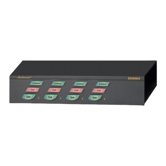
- Page 1 ES4000A Intercom Expansion Station User Instructions 9350-7551-000 Rev C 04-2006...
- Page 2 OTICE The product information and design disclosed herein were originated by and are the property of Telex Communications, Inc. Telex reserves all patent, proprietary design, manufacturing, reproduction, use and sales rights thereto, and to any article disclosed therein, except to the extent rights are expressly granted to others.
-
Page 3: Table Of Contents
Chapter 1 Introduction ...3 Description ...3 Features ...4 Chapter 2 Installation ...5 Unpacking ...5 Configuration Pre-check ...5 DIP Switches ...5 Program Interrupt DIP Switches ...5 Audiocom Call Send and Receive DIP Switches ...7 Balanced/Unbalance Switch (SW2) ...7 Direct Program Listen Enable / Disable Jumpers ...7 Sidetone Trimmers ...7 Mounting Configurations ...7 Connection Notes ...11... -
Page 5: Introduction
US2000A, and it provides talk, listen and call buttons for the 4 additional channels. There are also 4 additional program inputs on the back of the ES4000A, 1 for each added channel. Up to 4 ES4000A Expansion Stations may be connected to the US2000A to add up to 16 channels (18 channels total). -
Page 6: Features
EXP IN and EXP OUT connectors. An EXP IN/OUT cable is supplied with each ES4000A. SPEAKERS: Usually, the listen mix of all 4 ES4000A channels is sent to the US2000A speaker or headset via the EXP IN connector. Alternatively speakers may be connected to one or more of the speaker outputs of the ES4000A. -
Page 7: Installation
The ES4000A is supplied with the following items. Contact the shipper or your Audiocom dealer immediately if anything is damaged or missing. Detach and fill out the registration card and return it to Telex to properly register you intercom station. - Page 8 Installation Configuration Switch Settings TABLE 1. Switch Number SW1-1 Program Interrupt, Ch 6 SW1-2 Program Interrupt, Ch 5 SW1-3 Program Interrupt, Ch 4 SW1-4 Program Interrupt, Ch 3 SW1-5 Audio Call Send, Ch 3 SW1-6 Audio Call Send, Ch 3 SW1-7 Audio Call Send, Ch 4 SW1-8...
-
Page 9: Audiocom Call Send And Receive Dip Switches
Mounting Configurations The ES4000A can be used on a desktop, or it can be rack mounted. For desktop use, install the 4 rubber feet supplied with the ES4000A. For rack mounting, use optional Audiocom RMK Rack Mount Kits (Figure 3 on page 8). Many configurations are possible when using the kits. - Page 10 1/2-rack and 1/4-rack wide Audiocom components*. Mounts one 1/2-rack wide unit with 1/4-rack wide components, or 3 1/4-rack wide components. 1/2-rack wide components: US2000A, ES4000A, PS2000L, SPS2000A, PS4000, PS-X, SPK-2000, CIA-1000. 1/4-rack wide components: SPK-1000 Audiocom RMK Rack Mount Kits FIGURE 3.
- Page 11 10 channels. A microphone must be connected to the US2000A for talk on the 10 channels. Each PS4000 provides power for 4 intercom channels and also interfaces with an ES4000A to the intercom channels. The XP-USPG interfaces 2 external program inputs to the US2000A, and also interfaces the US2000A to an external PA system. Each XP-4PGM interfaces 4 external program sources to an ES4000A.
- Page 12 4 external program sources to the ES4000A. The XP-ES4000 interfaces 4 of the PS2000L power supplies to the 4 channels of the ES4000A. The connection between the US2000A and the ES4000A, as well as the connections of the XP-USPG and the XP-4PGM, are show in Figure 6. The power supply connections for the US2000A are shown in Figure 7.
-
Page 13: Connection Notes
PS2000L, etc.). Alternatively, you can use option PS-L Wall-pack Power Supplies. If you are using PS-L Wall-packs, connect them to the 12-15 VDC jacks on the back panels of the US2000A and ES4000A. When PS-L Wall-packs are used, the US2000A / ES4000A will not draw power from the intercom channel power supplies, leaving more power for belt packs. - Page 14 ES4000A Telex SPEAKERS PROGRAM INPUTS PGM VOLUME BAL-OUT LINE LEVEL UNBAL-IN 12-15 VDC 1 VRMS TO ANOTHER ES4000A CHN 2 MADE IN USA PUSH TO BELT PACKS CHN 2 AND REMOTE MASTER STATIONS CH 1 CH 2 CH 3 CH 4...
- Page 15 Connection Notes Channel 1 Power and All-Channel Speaker Combine / Isolate Switch set to Combine 100-240 VAC 60/50 HZ To ½ of stations on channel 1 Maximum Power Configuration for Channels 1 and 2. This power supply configuration should only be FIGURE 7.
- Page 16 It permits about twice as many remote stations on the 4 channels than is possible with the power supply configuration shown in Figure 6. TO US2000A EXP IN CONNECTOR 12-15 VDC XP-ES4000 TO THE EXP IN CONNECTOR OF ANOTHER ES4000A PUSH PUSH PUSH CH 6 CH 5 ®...
- Page 17 4 channels than is possible with the power supply configuration shown in Figure 6. TO US2000A EXP IN CONNECTOR 12-15 VDC XP-ES4000 TO THE EXP IN CONNECTOR OF ANOTHER ES4000A PUSH PUSH PUSH ® CHN 1 CHN 2 MADE IN USA CLASS 2 WIRING 1.5A 24VDC...
- Page 18 5 and 6 have about twice the capacity as the configuration shown in Figure 6. TO US2000A EXP IN CONNECTOR 12-15 VDC XP-ES4000 TO THE EXP IN CONNECTOR OF ANOTHER ES4000A PUSH PUSH PUSH ® CHN 1 CHN 2 MADE IN USA CLASS 2 WIRING 1.5A 24VDC...
- Page 19 OR BELT PACKS CH 1 CH 2 PUSH PUSH PGM 1 PGM 2 BAL - OUT CHN 1 CHN 2 UNBAL - IN CH 3-6 ES4000A Telex SPEAKERS ® PROGRAM INPUTS PGM VOLUME CAN 3-6 OUTPUTS BAL-OUT LINE LEVEL UNBAL-IN 1 VRMS...
- Page 20 Combine / Isolate Switches set to Combine Using the termination plugs supplied with the ES4000A for mixed wet- and dry-line operation. In this FIGURE 12. example, channels 5 and 6 are powered from a PS2000L Power Supply (wet lines), while channels 3 and 4 are operated without power (dry lines).
- Page 21 Connection Notes Using termination plugs for all dry-line connection. In this example, all components use local power FIGURE 13. supplies, and no power is supplied on the intercom channels. All stations may be operated over a much greater distance than is possible when using powered channels. IMPORTANT: there should only be one termination plug used in each channel.
-
Page 22: Cables
The numbers below correspond to the cable numbers in the connection drawings on the previous pages. 1-channel intercom cable. Sold separately. Use Telex “ME” cables, below. Or, build per Figure 14 on page 21. ME-25: 25’ (7.6m) cable with Male and Female 3-pin XLR connectors. - Page 23 Cables Shield Cable Type: 22AWG Stranded, 2-Pair Twisted-wire, with Shield Connector Type: 3-Pin XLR Audio (Neutrik or Switchcraft) Pin 1: Common Pin 2: Channel Audio / Power Pin 3: Channel Audio / Power Shield : Earth ground Shield Cable Type: 22AWG Stranded, 3-Pair Twisted-wire, with Shield Connector Type: 6-Pin XLR Audio (Neutrik only, not compatible with 6-pin Switchcraft) Pin 1: Channel 1 &...
- Page 24 Installation...
-
Page 25: Operation And Specifications
Power-Up The ES4000A channels power-up identically to channels 1 and 2 of the US2000A. Refer to the US2000A User Instructions for all power-up information. Sidetone Trimmer Access on Bottom of ES4000A FIGURE 15. Sidetone Adjustments Use the sidetone adjustment procedure as described in the US2000A User Instructions, except substitute channel 3, channel 4, etc. -
Page 26: Specifications
Operation and Specifications Specifications General Power Requirements Voltage Phantom Power: 24VDC nominal (12 to 30VDC) Local Power (with PS-L Wall-pack Power Supply or equivalent): 14 to 15 VDC Current: 65mA, quiescent; 150mA maximum Dimensions 1.75” (44.5 mm) high, 8.25” (209.6mm)wide, 10.0” (250mm) deep Environmental Requirements Storage: -20°C to 80°C;... - Page 27 Connector Pin Outs PROGRAM INPUTS Connector Connector Type: DB9F Female, 9-pin D-sub Pin 1: Common Pin 2: Channel 3 program in low Pin 3: Channel 4 program in low Pin 4: Channel 5 program in low Pin 5: Channel 6 program in low Pin 6: Channel 3 program in high Pin 7:...
-
Page 28: Addendum - Errata Sheet
18” (457mm) CHANNEL OUTPUT cable, 15-pin Male Dsub to 15-pin Male Dsub. One supplied with each ES4000A. NOTES: When you are connecting an ES4000A to a PS4000 Power Supply, use the CHANNEL OUTPUT cable that is supplied • with the ES4000A (cable 6). - Page 29 Addendum - Errata Sheet...