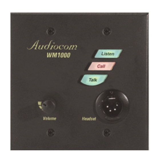
Telex Audiocom WM1000 User Instructions
Wall mount intercom stations
Hide thumbs
Also See for Audiocom WM1000:
- Addendum (1 page) ,
- User instructions (24 pages) ,
- User instructions (24 pages)
Table of Contents
Advertisement
Quick Links
Download this manual
See also:
Instructions for Using
Advertisement
Table of Contents

Related Manuals for Telex Audiocom WM1000


Summary of Contents for Telex Audiocom WM1000
- Page 1 Model WM1000/WM2000 Wall Mount Intercom Stations User Instructions 2 0 0 9350-7621-000 Rev D 5/2006...
- Page 2 UPS Ground, prepaid (you may request disclosed herein were originative by and from Factory Service a different shipment are the property of Telex Communication, method). Any shipment upgrades will be Inc. Telex reserves all patent, proprietary paid by the customer. The equipment...
- Page 3 Notes...
- Page 4 The WM1000 is a single-channel station; the WM2000 provides switch-selectable access to either of two intercom channels. The WM1000 and WM2000 are ideal when users need to access the intercom system from strategic locations where a desktop station would be unsuitable, but they do not wish to carry around a belt-pack station.
-
Page 5: Specifications General
Specifications General Power Requirements Phantom Power: 24VDC nominal (12 to 30 VDC), 65 to 150 mA Local Power: 12 to 15 VDC, 65 to 150 mA Dimensions Mounts in a standard two-gang electrical box Environmental Requirements Storage: -20° C to 80° C; 0% to 95% humidity, non-condensing Operating: -15°... -
Page 6: Operation
Each WM1000/2000 is supplied with the following items. Contact the shipper or your Audiocom dealer immediately if anything is damaged or missing. Detach and fill out the registration card and return it to Telex to properly register your intercom station. - Page 7 TO ADDITIONAL TO POWER SINGLE- OR TWO-CHANNEL STATIONS SUPPLY CONNECTOR Pair Pair Pair Shield* PIN 1 Cable Type: 22AWG Stranded, 3-Pair Twisted-wire, with Shield Denotes twisted pair. Denotes shield. *Shield: Earth ground (Connect at power supply only. Do not short to DC common) Figure 7.
-
Page 8: Intercom Channel Connections
Method 1: Phantom Powered Connection In this method, operating power and intercom audio are delivered to the WM1000/2000 over the same wires. The advantage of this setup is simplicity of connection. Also, the Audiocom power supply automatically provides terminating impedance for the intercom system. Without this terminating impedance, the sound quality on the channel will be very distorted, and the levels will shift every time additional stations are connected to the channel. -
Page 9: Dynamic-Mic Headset Connection
Each PS2000L is set to combine mode and it supplies power to one intercom channel only. Each intercom channel is a separate party line, and total current for each channel is limited to 2 amps. Note, both WM1000 and WM2000 Intercom Stations may be connected, depending on each locations’ need to communicate with one or two intercom channels. -
Page 10: Sidetone Adjustment
Figure 2. A two-channel intercom system using a PS2000L Power Supply set to isolate mode. In isolate mode, each intercom channel is a separate party line, and total current for each channel is limited to 1 amp. Note, both WM1000 and WM2000 stations may be connected, depending on each locations’ need to communicate with one or two channels.