Agilent Technologies 8890 Operation Manual
Gas chromatograph
Hide thumbs
Also See for 8890:
- Maintaining manual (282 pages) ,
- Installation and first startup (86 pages) ,
- User manual (86 pages)
Table of Contents
Advertisement
Quick Links
Advertisement
Table of Contents

Related Manuals for Agilent Technologies 8890


Summary of Contents for Agilent Technologies 8890
- Page 1 Agilent 8890 Gas Chromatograph Operation Manual...
- Page 2 Notices Warranty Safety Notices © Agilent Technologies, Inc. 2019 No part of this manual may be reproduced in The material contained in this doc- any form or by any means (including elec- ument is provided “as is,” and is C AU T I O N...
-
Page 3: Table Of Contents
Contents 1 Getting Started The 8890 Gas Chromatograph Before Operating Your GC Chromatography Using a GC Inlets Automatic injectors Automatic sampling valves GC Columns and Oven Detectors Touchscreen System Operation Touchscreen Browser Interface Data System Browser Interface Status Indicator... - Page 4 3 Startup and Shutdown To Start Up the GC To Shut Down the GC for Less Than a Week To Shut Down the GC for More Than a Week 4 Touchscreen Operation Navigation Run controls Status/control tray Entering Data Home View Flow path page Status page...
- Page 5 To run a method to process a single ALS sample To abort a method Events Using run time events Programming run time events The run table Editing events in the run table Deleting run time events Inlets Carrier gas flow rates About gas saver To set the PTV or COC coolant parameters To set MMI coolant parameters...
- Page 6 Recoverable Errors 7 Diagnostics About Diagnostics The system health report Automated testing Self-guided diagnostics Using the Diagnostics View Performing Diagnostic Tests 8 Maintenance Early Maintenance Feedback (EMF) Counter types Thresholds Default Thresholds Perform Maintenance Available Counters Viewing Maintenance Counters To Enable, Reset, or Change a Limit for an EMF Counter EMF Counters for Autosamplers Counters for 7693A and 7650 ALS with EMF-enabled firmware...
- Page 7 System Settings Configuring the IP address for the GC To set system date and time To change the system locale To set system power saving features To access stored run data To control Browser Interface access To change the Remote Advisor settings To change the miscellaneous settings To run the system setup routine Tools...
- Page 8 GC/MS systems To enable or disable MS communications To use the GC when the MS is shut down Headspace Sampler Headspace sampler configuration System-Level communications To enable or disable HS communications Miscellaneous Settings Readiness Valve Box PCMs Aux EPCs 12 Resource Conservation Resource Conservation Sleep methods...
- Page 9 About the Multimode Inlet MMI split mode minimum operating pressures Selecting the correct MMI liner About the Purged Packed Column Inlet About the Cool On-Column Inlet Setup modes of the COC inlet Retention gaps About the PTV Inlet PTV sampling heads About the Volatiles Interface VI operating modes About the VI split mode...
- Page 10 To Check FPD+ Performance (Sample 5188-5245, Japan) Preparation Phosphorus performance Sulfur performance 18 Chinese Metrology Testing FPD+ and ECD Unit Conversion Factors Conversion factors for the FPD+ Conversion factor for the ECD Using the Conversion Factors References 19 Glossary Operation Manual...
-
Page 11: Getting Started
Browser Interface 23 Status Indicator 27 GC Status 28 Overview of Running a Sample 29 Instrument Control 30 Correcting Problems 31 This document provides an overview of the Agilent 8890 Gas Chromatograph (GC) along with detailed operating instructions. Operation Manual... -
Page 12: The 8890 Gas Chromatograph
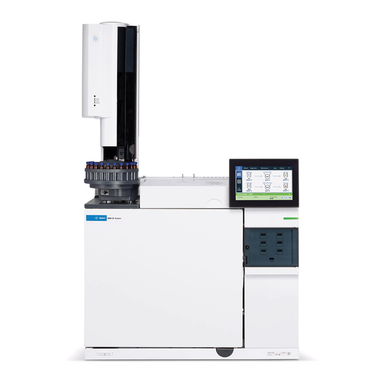
Getting Started The 8890 Gas Chromatograph Detectors Touchscreen Status Indicator Oven Smart ID Keys Power switch Figure 1. The 8890 GC Operation Manual... -
Page 13: Before Operating Your Gc
Getting Started Before Operating Your GC Before operating your GC, be sure to read the safety and regulatory information included on the Agilent GC and GC/MS User Manuals & Tools DVD, the Browser Interface or a connected web browser. The most common safety hazards when working on the GC are: •... -
Page 14: Chromatography Using A Gc
Getting Started Chromatography Using a GC Chromatography is the separation of a mixture of compounds into individual components. There are three major steps involved with separating and identifying components of a mixture using a GC. They are: 1 Injecting a sample into the GC. (This takes place at the inlet.) 2 Separating the sample into individual components. -
Page 15: Inlets
Getting Started Inlets Inlets are where samples are injected into the GC. The Agilent 8890 GC can have a maximum of two inlets, identified as Front Inlet and Back Inlet. The following inlet types are available: • Split/splitless inlet (SSL) •... -
Page 16: Gc Columns And Oven
The Agilent 8890 GC can accommodate up to six columns, identified as Column #1 through Column #6. The 8890 will have six Smart ID Key slots on the front of the instrument. These keys hold configuration information about the columns on the system. The Column Smart ID Keys will define column information that could be transferred between GCs. -
Page 17: Detectors
Getting Started Detectors Detectors identify the presence of compounds as they exit the column. As each compound enters the detector, an electrical signal proportional to the amount of compound detected is generated. This signal is generally sent to a data analysis system—such as Agilent OpenLAB CDS ChemStation edition—where it shows up as a peak on a chromatogram. -
Page 18: Touchscreen
Getting Started Touchscreen The touchscreen shows GC status and activity information, and allows you to start, stop, and prepare the GC to run a sample. The touchscreen also provides access to GC setpoints, real-time signals, diagnostics, maintenance information, logs, and instrument configuration settings. - Page 19 Getting Started Figure 4. Navigate between home, setpoints, automated maintenance, and help. Figure 5. Closable run control and status tray. “Touchscreen Operation” for a detailed description of the touchscreen functions and capabilities. Operation Manual...
-
Page 20: System Operation
Getting Started System Operation The GC can be controlled using the touchscreen, the Browser Interface, and an Agilent data system. Touchscreen The touchscreen provides direct control of configuration settings, access to diagnostic and maintenance functions, logs, and access to help, as well as the ability to make temporary changes in setpoints. -
Page 21: Browser Interface
Getting Started Browser Interface The Browser Interface provides many of the same functions as the touchscreen.The Browser Interface provides for instrument setup and control, as well as the ability to run the instrument stand-alone (without a connected data system). The Browser Interface can be viewed using any typical web browsing device, such as a computer or tablet, provided the device is connected to the same gateway as the GC. - Page 22 Getting Started In addition, the data system adapter provides access to the complete help and user information. From anywhere within the method editor for the GC, select Help and Information Browser Interface from the navigation tree. Also note: • The data system adapter does not provide direct access to all of the GC's diagnostic and maintenance features.
-
Page 23: Browser Interface
Getting Started Browser Interface You can control and monitor the GC using a web browser that is on the same gateway as the GC. An internet connection is not required. This Browser Interface can be accessed by using computer browser clients and mobile device client browsers, such as tablets. The Browser Interface provides complete control of the GC. - Page 24 Getting Started To connect to the GC using a browser: 1 If you do not know the GC's IP address or host name, use the touchscreen to find it. 2 Open a web browser. Supported browsers include Chrome, Safari (on a tablet), Internet Explorer 11, and Edge.
- Page 25 Getting Started For more information on how to utilize the Browser Interface, click the Help tab to access the Help & Information suite, or click the < on the right side of the screen to access the context sensitive help. See “Help from a Browser”...
- Page 26 Getting Started Browser Interface Help Figure 8. Complete Help and Information content This manual focuses on GC operation using the touchscreen. While many functions are similar between the touchscreen and Browser Interface, refer to the help provided in the Browser Interface when using it to control the GC.
-
Page 27: Status Indicator
Getting Started Status Indicator The GC includes a status indicator on the front panel to allow you to quickly determine the status and readiness of the GC. The status indicator changes color depending on the current state of the GC. •... -
Page 28: Gc Status
Getting Started GC Status When the GC is ready to begin a run, the touchscreen shows STATUS: READY FOR INJECTION. Alternately, when a component of the GC is not ready to begin a run, the touchscreen shows STATUS: NOT READY and the status indicator on the GC front panel is yellow. Tapping the Diagnostics tab displays indications of why the GC is not ready. -
Page 29: Overview Of Running A Sample
Getting Started Overview of Running a Sample Operating the GC involves the following tasks: • Setting up the GC hardware for an analytical method. • Starting up the GC. See “To Start Up the GC”. • Preparing any attached sampler. Install the method-defined syringe; configure solvent and waste bottle usage and syringe size;... -
Page 30: Instrument Control
Getting Started Instrument Control The Agilent 8890 GC is typically controlled by an attached data system such as Agilent OpenLAB CDS. Please refer to the online help included in the Agilent data system for details on how to load, run, or create methods and sequences using the data system. -
Page 31: Correcting Problems
Getting Started Correcting Problems If the GC stops operation because of a fault, check the touchscreen or Browser Interface for any messages. The GC includes diagnostics functions to help you determine the cause of a fault. 1 Use the touchscreen, Browser Interface, or data system to view the alert. (See “Home View”... - Page 32 Getting Started Operation Manual...
-
Page 33: Help And Information
Help and Information Where to Find Information 34 Help from the Touchscreen 35 Touchscreen Help 36 Help from a Browser 39 Context-Sensitive Help 43 Agilent GC and GC/MS User Manuals & Tools DVD 45 Operation Manual... -
Page 34: Where To Find Information
GC and GC/MS User Manuals & Tools DVD. When unpacking the instrument, make sure you take a look at the provided 8890 GC Quick Start Poster to help you quickly get familiar with your GC, as well as setup and configure your instrument. -
Page 35: Help From The Touchscreen
Help and Information Help from the Touchscreen Available right at your fingertips from the 8890 GC is an extensive amount of on-board documentation designed to assist with topics such as getting started, familiarization, installation, operation, maintenance, troubleshooting, and other useful information. -
Page 36: Touchscreen Help
Help and Information Touchscreen Help When using the GC, a help menu is available by selecting the question mark (?) in the upper right corner of the touchscreen. The help menu provides access to context-sensitive information about the screen you are viewing, tips, access to the full Help & Information suite, as well as an Index to assist in finding needed information. - Page 37 Help and Information 2 Tips provides helpful information on how to use the GC. Individual tips are provided which contain answers to frequently asked questions, as well as links to frequently used procedures. 3 Help & Information provides comprehensive, in-depth information related to maintenance, diagnostics, part views, operation, settings, and more.
- Page 38 Help and Information • Diagnostics: Automated and manual tests available on this GC. • Operation: How to use the inlets, detectors, and modules available on this configured • Familiarization: Where to find information regarding the GC, using the touch display, how to use the system setup wizard, accessing the feature tour, and an overview of the GC parts.
-
Page 39: Help From A Browser
Help and Information Help from a Browser You can access an extensive amount of on-board documentation that is designed to assist with topics such as getting started, familiarization, installation, operation, maintenance, troubleshooting, and other useful information. Access to the internet is not required to use this enhanced help package. - Page 40 Help and Information • Your Agilent data system. Access the Help & Information suite by clicking the Help & Information Browser Interface link at the top of the tree view. Operation Manual...
- Page 41 Help and Information • A web browser on any device that is on the same gateway as the GC. Access the Help & Information suite by typing http://xxx.xx.xx.xxx/info into your web browser of choice, where xxx.xx.xx.xxx is the IP address or host name of your GC. Accessing the Help &...
- Page 42 Help and Information In addition, you can set frequently visited topics as favorites for easy access. To do so, navigate to the desired topic, and click the icon. Once a topic has been added to your favorites, the icon becomes filled in. Click this icon again to remove the topic from your favorites.
-
Page 43: Context-Sensitive Help
Help and Information Context-Sensitive Help Available from each of the Browser Interface pages is the ability to access context-sensitive information or help. Select the < from the right side of the screen to access information and tips relevant to the page you are viewing. About this Screen provides several links to relevant help topics. - Page 44 Help and Information To minimize the topic you are viewing, click the > between the context sensitive help and the page you are viewing. Click the > again to minimize the context sensitive help tray. Operation Manual...
-
Page 45: Agilent Gc And Gc/Ms User Manuals & Tools Dvd
Help and Information Agilent GC and GC/MS User Manuals & Tools DVD The Agilent GC and GC/MS User Manuals & Tools DVD provides an extensive collection of online help and books for current Agilent gas chromatographs, mass selective detectors, and GC samplers. - Page 46 Help and Information Operation Manual...
-
Page 47: Startup And Shutdown
Startup and Shutdown To Start Up the GC 48 To Shut Down the GC for Less Than a Week 49 To Shut Down the GC for More Than a Week 50 Operation Manual... -
Page 48: To Start Up The Gc
Successful operation begins with a properly installed and maintained GC. The utility requirements for gases, power supply, venting of hazardous chemicals, and required operational clearances around the GC are detailed in the Agilent 8890 Gas Chromatograph Site Preparation Guide. 1 Check gas source pressures. For required pressures, see the Agilent 8890 Gas Chromatograph Site Preparation Guide. -
Page 49: To Shut Down The Gc For Less Than A Week
Startup and Shutdown To Shut Down the GC for Less Than a Week 1 Wait for the current run to finish. 2 If the active method has been modified, save the changes. Never leave flammable gas flows on if the GC will be unmonitored. If a leak develops, the gas WAR N IN G could create a fire or explosion hazard. -
Page 50: To Shut Down The Gc For More Than A Week
Startup and Shutdown To Shut Down the GC for More Than a Week 1 Put the GC into general maintenance mode by selecting Maintenance > Instrument > Perform Maintenance > Start Maintenance, and wait for the GC to become ready. 2 Turn off the main power switch. -
Page 51: Touchscreen Operation
Touchscreen Operation Navigation 52 Run controls 53 Status/control tray 54 Entering Data 55 Home View 56 Flow path page 57 Status page 58 Plot page 59 Methods View 61 Diagnostics View 62 Maintenance View 63 Logs View 64 Settings View 65 Help Menu 66 Touchscreen Functionality When the GC Is Controlled by an Agilent Data System 67 This section describes the basic operation of the Agilent GC touchscreen. -
Page 52: Navigation
Touchscreen Operation Navigation The touchscreen shows GC status and activity information (current temperatures, flows, pressures, and information about GC readiness), and allows you to start, stop, and prepare the GC to run a sample. The touchscreen also provides access to GC setpoints, real-time signals, diagnostics, maintenance information, logs, and instrument configuration settings. -
Page 53: Run Controls
Touchscreen Operation Depending on which page is selected, additional controls may appear. This can include page selection buttons, selectable tabs, back and next buttons, scroll buttons, and so on. Figure Additional controls Selectable tabs Previous or higher level page Page selection buttons Scroll buttons Figure 10. -
Page 54: Status/Control Tray
Touchscreen Operation The Stop control immediately terminates the run. If the GC is in the middle of a run, the data from that run may be lost. For details on running methods, see “Running Methods”. Status/control tray The status/control tray provides details on the current status of the GC, the current sequence and method (if connected to an Agilent data system), the time remaining for the current operation being performed by the GC, run controls, and so on. -
Page 55: Entering Data
Touchscreen Operation Entering Data When you touch a data entry field, a touch keyboard or keypad appears, as applicable. Figure Touch keypad Figure 12. Touch keypad for data entry If you enter an out of range entry, it is highlighted in a different color. If the field is a drop-down list box (indicated by a down arrow to the right of the displayed contents of the field), select it to open the list, and then select the desired entry. -
Page 56: Home View
Touchscreen Operation Home View The home view’s Flow Path page shows flow path information (including current temperatures and flow rates), run status (including user selectable status items), a real-time plot of the current chromatogram, and related information. See Figure Page selection buttons Figure 14. -
Page 57: Flow Path Page
Touchscreen Operation Flow path page The flow path page provides details on sample flow through the GC. This includes visual indications of whether an ALS is installed on the GC, the inlet type(s), column setup, and detector type(s), along with corresponding setpoints. See Figure Figure 15. -
Page 58: Status Page
Touchscreen Operation Status page The status page displays a user-selectable list of parameters, along with their setpoints and actual values. See Figure Figure 16. Home view - status page Selecting + Add brings up a dialog box which allows you to choose a parameter to add to the displayed list. -
Page 59: Plot Page
Touchscreen Operation Plot page The plot page displays a plot of the currently selected signal. See Figure Figure 18. Home view - plot page Clicking or tapping the plot cycles the displayed zoom between 1x, 2x, and 4x at the point where the plot is clicked or tapped. - Page 60 Touchscreen Operation Use the Signal Name drop down list box to select which parameter to display on the plot. The displayed X-Axis interval is 1 to 60 minutes. The Y-Axis Range is negative infinity to infinity. Selecting either field brings up a keypad which allows you to set the corresponding value.
-
Page 61: Methods View
Touchscreen Operation Methods View From the touchscreen, the Methods view provides access to the method currently being used (Active Method). Use this view to edit the Active Method. From the Browser Interface, The Methods view provides access to the locally-stored methods, including the method currently being used (Active Method). -
Page 62: Diagnostics View
Touchscreen Operation Diagnostics View The Diagnostics view provides access to diagnostic tests for the installed inlet and detectors, as well as access to the System Health Report. Additionally, the view provides a list of all current alerts. Figure 21. Diagnostics view “Diagnostics”... -
Page 63: Maintenance View
Touchscreen Operation Maintenance View The Maintenance View provides access to the Agilent GC Early Maintenance Feedback (EMF) features. See Figure Figure 22. Maintenance view EMF provides injection-based, run-based, and time-based counters for various consumable and maintenance parts, as well as the instrument itself. Use these counters to track usage of GC components. -
Page 64: Logs View
Touchscreen Operation Logs View The Logs view provides listings of GC events including maintenance events, run events, and system events, sorted by date/time. See Figure Figure 23. Logs view “Logs” for more details. Operation Manual... -
Page 65: Settings View
Touchscreen Operation Settings View The Settings View provides access to instrument configuration functions, scheduler functions, service mode settings, calibration settings, system settings, system tools, power controls (restart or shutdown) and system details. See Figure Figure 24. Settings view “Settings” for more details. Operation Manual... -
Page 66: Help Menu
Touchscreen Operation Help Menu The Help view can be accessed by selecting the ? tab. From here, you can access a full Help and Information suite, additional information about the screen you are currently viewing, and more. See “Touchscreen Help” for more information on what each option in the dropdown menu provides. -
Page 67: Touchscreen Functionality When The Gc Is Controlled By An Agilent Data System
Touchscreen Operation Touchscreen Functionality When the GC Is Controlled by an Agilent Data System When an Agilent data system controls the GC, the data system defines the setpoints and runs the samples. If configured to lock the touchscreen, the data system can prevent the changing of setpoints. - Page 68 Touchscreen Operation Operation Manual...
-
Page 69: Methods
Methods What is a Method? 70 What Is Saved in a Method? 71 What Happens When You Load a Method? 72 Editing the Active Method 73 Create a Method 74 Load a Method 75 Running Methods 76 Events 78 Inlets 80 About gas saver 81 To set the PTV or COC coolant parameters 82 To set MMI coolant parameters 82... -
Page 70: What Is A Method
Methods What is a Method? A method is the group of settings required to analyze a specific sample. Since every type of sample reacts differently in the GC—some samples require a higher oven temperature, others require a lower gas pressure or a different detector—a unique method must be created for each specific type of analysis. -
Page 71: What Is Saved In A Method
Methods What Is Saved in a Method? Some of the settings saved in a method define how the sample will be processed when the method is used. Examples of method settings include: • The oven temperature program • The type of carrier gas and flows •... -
Page 72: What Happens When You Load A Method
Methods What Happens When You Load a Method? There are two kinds of methods: • The active method—This is sometimes referred to as the current method. The settings defined in this method are the settings the GC is currently maintaining. •... -
Page 73: Editing The Active Method
Methods Editing the Active Method The Active Method is the current collection of setpoints being used by the GC. Using the touchscreen you can edit these settings, and any changes apply immediately. When you download a method from the Browser Interface or an Agilent data system, that method becomes the new Active Method. -
Page 74: Create A Method
Methods Create a Method Methods may be created using your Agilent data system, or via the Browser Interface. For more information on creating a method using your data system, refer to the documentation provided with your data system. From the Browser Interface: 1 Click Method on the control ribbon. -
Page 75: Load A Method
Methods Load a Method 1 Connect to the GC using the Browser Interface. See “Browser Interface”. 2 Open or create the desired method. See “Create a Method”. 3 If needed, click the Save button to save the method. 4 Click the Download button to load the method to your GC. -
Page 76: Running Methods
Methods Running Methods Pre Run and Prep Run With some inlets and operating modes, certain instrument setpoints are different between runs than during an analysis. To restore the setpoints for injection, you must place the GC into the Pre Run state. You must use the Pre Run state when: •... -
Page 77: To Run A Method To Process A Single Als Sample
Methods 3 Navigate to the Home view and select Prep Run . See “Run controls” for more information. 4 Wait for status Ready to display. 5 Insert the syringe needle through the septum and all the way into the inlet. 6 Simultaneously depress the syringe plunger to inject the sample and select Start To run a method to process a single ALS sample 1 Prepare the sample for injection. -
Page 78: Events
Methods Events Run time programming during a method allows certain setpoints to be changed during a run as a function of the chromatographic run time. Thus an event that is programmed to occur at 2 minutes will occur 2 minutes after every injection. •... -
Page 79: Programming Run Time Events
Methods Programming run time events 1 Select Method. 2 Select Events. 3 Input the time at which you want the event to occur, select the event you want to program, select the position of the hardware that is being controlled, and set the desired setpoint. The run table The programmed events are arranged in order of execution time in the Run Table. -
Page 80: Inlets
Methods Inlets The Inlets page in the Method tab is used to modify the method parameters and each inlet connected to your GC. Common parameters include the heater temperature and inlet pressure. See Figure 25. To modify your inlets’ method parameters: 1 Select Method >... -
Page 81: About Gas Saver
Methods Table 3 Column size and carrier flow rate (continued) Column type Column size Carrier flow rate, mL/min Hydrogen Helium Nitrogen 0.32 mm id 0.75 0.53 mm id About gas saver Gas saver reduces carrier flow from the split vent after the sample is on the column. It applies to the Split/Splitless, Multimode, and PTV inlets (all modes) and to the split and splitless modes of the Volatiles Interface. -
Page 82: To Set The Ptv Or Coc Coolant Parameters
Methods 5 Input the Time. To set the PTV or COC coolant parameters Select Method > Inlets. Use the down arrow to scroll until the cryo settings are visible Cryo Cooling Selecting the checkbox next to Cryo Cooling enables cryogenic cooling of the inlet at the specified Cryo use temperature setpoint, Deselecting the checkbox disables cooling. - Page 83 Methods Fault Detection This parameter is available with N2 cryo and CO2 cryo Cryo types. Shuts down the inlet temperature if it does not reach setpoint in 16 minutes of continuous cryo operation. Note that this is the time to reach the setpoint, not the time to stabilize and become ready at the setpoint.
-
Page 84: About Oven Temperature Programming
Methods About Oven Temperature Programming You can program the oven temperature from an initial temperature to a final temperature using up to 20 ramps during a run. A single ramp temperature program raises the initial oven temperature to a specified final temperature at a specified rate and holds at the final temperature for a specified period of time. -
Page 85: Oven Cryogenic Cooling Parameters
Methods Table 4 Oven ramp rates (continued) 100/120 V oven 200/220/230/240 V oven ramp rate (°C/minute) ramp rate (°C/minute) Temperature Without insert With optional Without insert With optional range (°C) insert insert 70 to 115 115 to 175 175 to 300 300 to 450 Isothermal runs... - Page 86 Methods Fault Detection Shuts the oven down if it does not reach setpoint temperature after 16 minutes of continuous cryo operation. Note that this is the time to reach the setpoint, not the time to stabilize and become ready at the setpoint. For example, with a cool on-column inlet and cryo control in the oven track mode, it may take the oven 20 to 30 minutes to achieve readiness.
-
Page 87: Columns
Methods Columns The column flow mode determines whether pressure or flows are available as setpoints for the GC inlets. When all columns in the flow path are defined, you can enter pressures or flows. If any column in the flow path is not defined, then the settings for the inlet may be restricted based on the inlet type and whether the column is in flow or pressure mode. -
Page 88: Nickel Catalyst Tube
Methods Nickel Catalyst Tube About the nickel catalyst tube The Nickel Catalyst Tube accessory, 3534A, is used for trace analysis of CO and CO with a flame ionization detector. The gas sample is separated on the column and passed over a heated catalyst in the presence of hydrogen, which converts the CO and CO peaks to CH Sample... -
Page 89: Detectors
Methods Detectors For help creating a new method, or troubleshooting detector problems, see the recommended starting conditions for each detector. The makeup gas line of your detector parameter list changes depending on your instrument configuration. If you have an inlet with the column not defined, the makeup flow is constant. FID automatic reignition (Lit offset) Lit offset is the expected minimum difference between the FID output with the flame lit and the output with the flame off. -
Page 90: Fpd
Methods Table 5 Recommended starting conditions (continued) Gas type Suggested flow rate Detector gases Hydrogen 40 mL/min 450 mL/min Column plus capillary makeup (N 50 mL.min recommended, or He as an alternative) Detector Temperature If < 150 °C, the flame will not light. Agilent recommends a temperature 300 °C to prevent condensation damage. -
Page 91: Npd
Methods The emission block temperature ranges from 125—175 °C. Typically, the default temperature of 150 °C is sufficient for most applications. However, when setting the emission block temperature, consider the following: • If using the GC oven at high temperature (>325 °C) with the transfer line set to 400 °C, set the emission block temperature to 165 °C to avoid a system Not Ready if the emission block temperature cannot be maintained. - Page 92 Methods Extending the NPD bead life These actions, together with the automated heatup and adjust procedures, can extend bead life considerably. • Use the lowest practical Adjust Offset value. This will result in a lower applied bead current during operation. •...
-
Page 93: Tcd
Methods Chemically active compounds reduce TCD filament life The tungsten-rhenium TCD filament has been chemically passivated to protect against oxygen damage. However, chemically active compounds such as acids and halogenated compounds may attack the filament. The immediate symptom is a permanent change in detector sensitivity due to a change in filament resistance. -
Page 94: Ecd
Methods Table 8 Recommended starting conditions (continued) Gas type Suggested flowrates <135 C, cannot turn on filament If detector temperature goes below 120 °C, the filament turns off. Detector temperature should be 30 °C to 50 °C greater than the highest oven ramp temperature. - Page 95 Methods Table 9 Recommended starting conditions (continued) Gas type Suggested flow rates Temperature 250 C to 400 C Detector temperature is typically set 25 C greater than the highest oven ramp temperature. Operation Manual...
-
Page 96: Valves
Methods Valves The valve box The GC holds up to four valves in a heated valve box on top of the oven. The valve box is the preferred location for valves because it is a stable temperature zone, isolated from the column oven. Valve box, shown with 3 valves Valve heater... - Page 97 Methods Table 10 Valve drivers (continued) Valve number Type Volts Power or current 5 and 6 Current source 24 VDC 100 mA Relays and low-power devices 7 and 8 Contact closure 48 VDC or 48 VAC RMS Control an external current source The internal valve drivers Valve drivers 1 through 4, 9, and 10 are usually used to control pneumatically operated valves...
-
Page 98: Valve Types
Methods Interface Valve 5 (pin 1) and ground (pin 3 or 4) Valve 6 (pin 2) and External valve drivers ground (pin 3 or 4) Run table (5 through 8) Valve 7 (pin 5 and pin 6) Valve 8 (pin 7 and pin 8) Clock table Valve types... - Page 99 Methods Front column From inlet or sampling valve To detector Back column When the valve is set to On, the front column is selected. When the valve is set to Off, the back column is selected Use a run table entry to ensure that the valve is in the Off state between runs. Sampling valve If a valve is configured as a sampling valve, it starts a run automatically when it is switched to the Inject position.
- Page 100 Methods Load time Time in minutes that the valve remains in the Load position before becoming ready. Inject time Time in minutes that the valve remains in the Inject position before returning to the Load position. The sampling valve cycle is: 1 The sampling valve rotates to the Load position.
- Page 101 Methods Step time In seconds, is a delay between successive actuator movements. It allows time for the actuator mechanism to prepare for the next movement. BCD Inverted Complements the BCD input; 1’s become 0’s and 0’s become 1’s. This accommodates coding convention differences among manufacturers. Operation Manual...
-
Page 102: Gc Output Signals
Methods GC Output Signals Signal is the GC output to a data handling device, analog or digital. It can be a detector output or the output from flow, temperature, or pressure sensors. Two signal output channels are provided. Signal output can be either analog or digital, depending on your data handling device. Analog output is available at either of two speeds, suitable to peaks with minimum widths of 0.004 minutes (fast data rate) or 0.01 minutes (normal rate). - Page 103 Methods This is used to correct baseline elevation or offsets. A common application is to correct a baseline shift that occurs as the result of a valve operation. After zeroing, the analog output signal is equal to the Value line of the parameter list minus the Zero setpoint. Zero can be programmed as a run time event.
-
Page 104: Digital Signals
Methods There are limits to usable range settings for some detectors. The table lists the valid range setpoints by detector. Table 12 Range limits Detector Usable range settings (2 0 to 13 0 to 13 FPD+ 0 to 13 0 to 6 0 to 6 Analog input 0 to 7... - Page 105 Methods Digital signal outputs respond to a zero command by subtracting the signal level at the time of the command from all future values. Signal Freeze and Resume Available only from an Agilent data system. Some run time operations, such as changing signal assignments or switching a valve, can cause baseline upsets.
- Page 106 Methods Table 13 Agilent data system data processing Data rate, Hz Minimum peak Relative Detector Column type width, minutes noise 1000 0.0002 6.96 FID/NPD Narrow-bore, 0.05 mm 0.0004 FID/NPD Narrow-bore, 0.05 mm 0.001 FID/FPD+/NPD Narrow-bore, 0.05 mm 0.002 FID/FPD+/NPD Capillary 0.004 ECD/FID/FPD+/NPD 0.01...
-
Page 107: Column Compensation
Methods Relative noise level Excess noise (due to flow, oven temperature, detector block temperatures, etc.) Faster data rates Slower data rates Column compensation In temperature programmed analysis, bleed from the column increases as the oven temperature rises. This causes a rising baseline which makes peak detection and integration more difficult. -
Page 108: Test Plot
Methods All conditions must be identical in the column compensation run and the real run. The same detector and column must be used, operating under the same temperature and gas flow conditions. Test plot Test plot is an internally generated “chromatogram” that can be assigned to a signal output channel. -
Page 109: Sequences
Sequences What is a Sequence? 110 Recoverable Errors 111 Operation Manual... -
Page 110: What Is A Sequence
Sequences What is a Sequence? A sequence is a list of samples to be analyzed along with the method to be used for each analysis. Sequences can be set up from the Browser Interface, or from the connected Agilent data system. Refer to the help provided in the Browser Interface or data system for details. Operation Manual... -
Page 111: Recoverable Errors
Sequences Recoverable Errors For details on how this feature works in your data system, refer to its help and documentation. Some types of errors, such as an ALS missing vial error or a headspace sampler vial size mismatch, may not always justify stopping an entire sequence. These errors are called recoverable errors, since you may be able to recover from them and continue running a sequence, if desired. - Page 112 Sequences Operation Manual...
- Page 113 Diagnostics About Diagnostics 114 The system health report 114 Automated testing 115 Self-guided diagnostics 115 Using the Diagnostics View 117 Performing Diagnostic Tests 118 Operation Manual...
-
Page 114: About Diagnostics
Diagnostics About Diagnostics The GC provides diagnostics features for inlets, detectors, and other installed components. This includes tests that are performed by the operator and automated testing that is performed by the GC without operator intervention. The Diagnostics view provides access to the system health report and operator initiated diagnostic tests. -
Page 115: Automated Testing
Diagnostics Automated testing The GC performs continuous, automated testing of the following items. If a failure occurs, an alert appears on the diagnostic tab. See Figure 27. In addition, an entry is made in the appropriate log. See below for a list of the continuous monitoring dialogs: Detector: •... - Page 116 Diagnostics Detector tests: • FID Jet Restriction test • FID Leakage Current test Operation Manual...
-
Page 117: Using The Diagnostics View
Diagnostics Using the Diagnostics View To use the Diagnostics view: 1 Select Diagnostics. The Diagnostics view appears. The view provides a list of all current alerts. 2 Select Diagnostic Tests. The Diagnostic Tests page appears. See Figure Figure 28. Diagnostic Tests page 3 Select Inlets, Detectors, or Other, as desired. -
Page 118: Performing Diagnostic Tests
Diagnostics Performing Diagnostic Tests To perform a diagnostic test: 1 Access the desired test from the Diagnostics view. See “Using the Diagnostics View”. 2 Select the desired test. The corresponding test page appears. The test page includes a test description and an indication of the parameter being tested. See Figure Figure 30. - Page 119 Diagnostics The currently running test can be aborted by selecting Cancel. This brings up a dialog box which allows you to confirm that you want to cancel the test. See Figure Figure 32. Abort dialog box Operation Manual...
- Page 120 Diagnostics Operation Manual...
-
Page 121: Maintenance
These procedures also include automated tests as needed to help- be sure the GC is ready when maintenance is complete. See the 8890 Maintaining Your GC manual for more information. -
Page 122: Early Maintenance Feedback (Emf)
Maintenance Early Maintenance Feedback (EMF) The 8890 provides injection- and time-based counters for various consumable and maintenance parts. Use these counters to track usage and replace or recondition these items before potential degradation impacts the chromatographic results. If using an Agilent data system, these counters can be set and reset from within the data system. -
Page 123: Thresholds
Maintenance Thresholds The EMF feature provides two warning thresholds: Service Due and Service Warning. When either threshold is passed, an indication appears on the Maintenance tab on the GC touchscreen ribbon. Selecting the Maintenance tab brings up the Maintenance view. See Figure Figure 33. -
Page 124: Perform Maintenance
Maintenance Perform Maintenance For many common maintenance procedures, your GC contains a detailed walkthrough of each procedure. These procedures may be accessed by selecting Maintenance > your desired component > Perform Maintenance. Once here, select your desired maintenance procedure, and select Start Maintenance to begin the walkthrough. Many maintenance procedures require you to put the GC in maintenance mode prior to performing any maintenance. -
Page 125: Available Counters
Maintenance Available Counters Table 14 lists the most common counters available. The available counters will vary based on the installed GC options, consumables, and future updates. Table 14 Common EMF counters Parts with a counter Type Default value Component Detectors Collector Number of injections Number of injections... - Page 126 Maintenance Table 14 Common EMF counters (continued) Parts with a counter Type Default value Component Liner O-ring Number of injections 1000 Liner O-ring Time 60 days Septum Number of injections Split vent trap Number of injections 10,000 Split vent trap Time 6 months Cooling cycles...
- Page 127 Maintenance Table 14 Common EMF counters (continued) Parts with a counter Type Default value Component Instrument On time Time Run count Number of runs Filters Time ALS Injectors Syringe Number of injections Syringe Time 2 months Needle Number of injections Plunger moves Value 6000...
-
Page 128: Viewing Maintenance Counters
Maintenance Viewing Maintenance Counters To view the maintenance counters: 1 Select the Maintenance tab. See Figure 2 Select the desired component type. The Status column lists the counter for the corresponding component. See Figure Figure 34. Detector Maintenance page 3 Scroll to view additional components, as applicable. Operation Manual... -
Page 129: To Enable, Reset, Or Change A Limit For An Emf Counter
Maintenance To Enable, Reset, or Change a Limit for an EMF Counter When using the GC without a data system, enable or change the limit for a counter as follows: 1 Locate the counter you wish to change. See “Viewing Maintenance Counters”. -
Page 130: Emf Counters For Autosamplers
EMF counters. • The injector counters will increment as long as the injector is used on an 8890 Series GC. You can change positions on the same GC or install the injector on a different GC without losing the current ALS counter data. -
Page 131: Emf Counters For Ms Instruments
Maintenance EMF Counters for MS Instruments When configured to an Agilent MS that supports enhanced communications (such as a 5977 Series MSD or 7000C Triple Quadrupole MS), the GC reports the EMF counters as tracked by the MS. The MS provides its own EMF tracking. When connected to an earlier model MS (for example, a 5975 Series MSD or 7000B MS), the GC tracks the MS counters, not the MS. - Page 132 Maintenance Operation Manual...
- Page 133 Logs Logs View 134 Maintenance logs 135 Run log 135 System log 135 This section describes the log features available on the Agilent 8890 GC. Operation Manual...
-
Page 134: Logs
Logs Logs View The Logs view provides listings of GC events including maintenance events, run events, and system events, sorted by date/time. See Figure Figure 36. Logs view Selecting one of the buttons on the Logs view brings up the corresponding log page. Figure Figure 37. -
Page 135: Maintenance Logs
Logs Use the scroll buttons to scroll through the log entries. Select Cancel to return to the Logs view. Maintenance logs The maintenance log contains entries made by the system when: • A system event occurs (for example, a detector shutdown) •... - Page 136 Logs Operation Manual...
-
Page 137: Settings
Settings About Settings 138 Service Mode 139 About 141 Calibration 142 Maintaining EPC calibration—inlets, detectors, PCM, PSD, and AUX 143 To zero a specific flow or pressure sensor 144 System Settings 145 Configuring the IP address for the GC 146 To set system date and time 147 To change the system locale 148 To set system power saving features 149... -
Page 138: About Settings
10 Settings About Settings The Settings view provides access to configuration and system settings for the GC. Selecting Settings on the touchscreen control ribbon brings up the Settings view. Figure Figure 38. Settings view • Select Configuration to access the GC configuration settings. See “Configuration”. •... -
Page 139: Service Mode
10 Settings Service Mode The Service Mode feature allows you to view the installed GC system component details. This includes serial numbers, firmware versions, voltages, currents, temperatures, and so on. Figure 39. Service Mode page To view the specifications for the various components of your instrument: 1 Select the desired component type. - Page 140 10 Settings 2 Use the page selection buttons on the left side of the page to display related functional information. Operation Manual...
-
Page 141: About
10 Settings About The About feature allows you to view details about the GC. The About screen lists the GC manufacturing date, serial number, firmware revision, and help and information revision. Figure 41. About page Select Close on the About page to return to the Settings view. Operation Manual... -
Page 142: Calibration
10 Settings Calibration Calibration allows you to adjust the following items (when available): • • Inlets • Oven • Detectors • EPC modules Figure 42. Calibration page To change the calibration settings: 1 Use the page selection buttons on the left side of the page to display related functional information. -
Page 143: Maintaining Epc Calibration-Inlets, Detectors, Pcm, Psd, And Aux
10 Settings Maintaining EPC calibration—inlets, detectors, PCM, PSD, and AUX The EPC gas control modules contain flow and/or pressure sensors that are calibrated at the factory. Sensitivity (slope of the curve) is quite stable, but zero offset requires periodic updating. Flow sensors All inlet modules use flow sensors, as do PSDs, and channel 1 of a PCM. -
Page 144: To Zero A Specific Flow Or Pressure Sensor
10 Settings To zero a specific flow or pressure sensor 1 Select Settings > Calibration > Detectors, and select the desired detector. 2 Select On next to the desired sensor to zero it. 3 For Flow sensors. Verify that the gas is connected and flowing (turned on). 4 For Pressure sensors. -
Page 145: System Settings
10 Settings System Settings System settings includes setting the network address, system date and time, touchscreen theme, disk space and data settings, locale setting, system setup information, and status parameter settings. Figure 43. System Settings page Use the page selection buttons on the left side of the page to display related functional information. -
Page 146: Configuring The Ip Address For The Gc
10 Settings Configuring the IP address for the GC For network (LAN) operation, the GC needs an IP address. It can get this from a DHCP server, or it can be entered directly from the touchscreen. In either case, see your LAN administrator for appropriate settings. -
Page 147: To Set System Date And Time
10 Settings To set system date and time 1 From the System Settings page, select the Date and Time page selection button. The Date and Time page appears. See Figure Figure 45. System Settings page 2 Select the Current Date field. A keypad appears. 3 Enter the current date. -
Page 148: To Change The System Locale
10 Settings To change the system locale 1 From the System Settings page, select the Locale page selection button. The Locale Settings page appears. See Figure Figure 46. Locale Settings page 2 Choose the desired Language from the corresponding drop-down list box. 3 Select Apply. -
Page 149: To Set System Power Saving Features
10 Settings To set system power saving features 1 From the System Settings page, select the Power Saving page selection button. The Power Saving page appears. See Figure Figure 47. Power Saving page 2 To enable display dimming: a Select the Dim display after: check box. The corresponding data entry fields and drop-down list box are enabled. -
Page 150: To Access Stored Run Data
10 Settings To access stored run data If using the Browser Interface to perform runs and collect data, the GC stores the result data internally. To access that data: 1 From the System Settings page, select Access. Note the displayed PIN. 2 Select Local Data Storage. -
Page 151: To Change The Remote Advisor Settings
10 Settings To change the Remote Advisor settings Remote advisor is a monitoring service designed to identify and react to problems with the GC. The GC constantly monitors its own health status and generates reporting information which is forwarded to Agilent. 1 From the System Settings page, select the Remote Advisor page selection button. - Page 152 10 Settings 3 Enter the polling frequency for data collection on the GC in the Monitor Period field. This determines the frequency at which the GC collects data and sends its health report details to Agilent. This value is in seconds. 4 When there are additional devices installed on the GC (such as a purge and trap device) which are covered by the Remote Advisor agreement, these devices are identified on the User Defined Modules tab.
- Page 153 10 Settings c Enter the Product Name in the corresponding field. d Select Add Information. The Hardware Info dialog box appears. See Figure Figure 51. Remote Advisor page - Hardware Info dialog box e Enter details for the device in the appropriate fields. f Select OK.
-
Page 154: To Change The Miscellaneous Settings
10 Settings To change the miscellaneous settings The miscellaneous settings include whether to load the last loaded method when the GC is powered on and whether to run an automated split vent trap test run on a periodic basis. 1 From the System Settings page, select the Miscellaneous page selection button. The Miscellaneous page appears. -
Page 155: To Run The System Setup Routine
10 Settings To run the system setup routine 1 From the System Settings page, select the System Setup page selection button. The System Setup page appears. See Figure Figure 53. System Setup page 2 Select Run System Setup. A set of demonstration slides is displayed on the touchscreen. These slides illustrate the primary steps for setting up your GC for use. -
Page 156: Tools
10 Settings Tools The Tools page allows you to perform column compensation runs for the installed columns on the GC. See Figure Figure 54. Tools page In temperature programmed analysis, bleed from the column increases as the oven temperature rises. This causes a rising baseline which makes peak detection and integration more difficult. -
Page 157: Performing A Column Compensation Run
10 Settings Performing a column compensation run All conditions must be identical in the column compensation run and the real run. The same detector and column must be used, operating under the same temperature and gas flow conditions. Up to four column compensation runs can be made. The GC retains the results of these runs for later use. -
Page 158: Power
10 Settings Power The Power Options dialog box allows you to shut down or restart the GC from the touchscreen. Figure 55. Power Options dialog box To restart the GC, select Restart. The GC restarts. To shut down the GC, select Shut Down. The GC shuts down. Operation Manual... -
Page 159: Configuration
Configuration About Configuration 160 Configuration Changes 161 Valve Configuration 163 Inlet Configuration 165 Columns 167 To configure a single column 168 To configure a packed column 169 To configure a composite column 169 Additional notes on column configuration 171 To configure multiple columns 171 Inlets and outlets 172 A simple example 172 Slightly more complex example 173... -
Page 160: About Configuration
11 Configuration About Configuration A device’s configuration properties are constant for an instrument hardware setup, unlike method settings which can change from sample run to sample run. Two example configuration settings are the gas type flowing through a pneumatic device and the operating temperature limit of a device. -
Page 161: Configuration Changes
11 Configuration Configuration Changes Configure a new device Upon startup, the GC will attempt to identify any device that was not installed prior to shutdown. The GC may require you to provide additional information, such as the type of device installed, or which heater a given device was attached to. To configure a new device: 1 Select Settings >... - Page 162 11 Configuration 1 Select Settings. The Settings view appears. See Figure Figure 56. Settings view 2 Select Configuration. Figure 57. Configuration page 3 Select the desired device type from the list on the left side of the screen. The properties for the selected device type appear on the right side of the screen.
-
Page 163: Valve Configuration
11 Configuration Valve Configuration Valve configuration provides the ability to specify valve types, loop volumes, step times, and BCD inversion settings. BCD inversion allows for changing the BCD input (1’s become 0’s and 0’s become 1’s). This feature accommodates coding convention differences between valve manufacturers. - Page 164 11 Configuration 3 Enter the loop volume using the corresponding Loop Vol. text field. 4 Enter the Step Time in the corresponding test field 5 For multi-position valves, use the BCD Inverted drop-down list box to select the whether to invert the BCD input.
-
Page 165: Inlet Configuration
11 Configuration Inlet Configuration 1 Select Settings > Configuration > Inlets. The properties for the selected device type appear on the right side of the screen. See Figure Figure 59. Inlets page 2 Select the desired gas type from the Carrier Gas Type drop-down list box. 3 Select Enable under Readiness if using this inlet. - Page 166 11 Configuration 4 Adjust the settings for the second inlet as necessary. 5 Select Apply. The entered changes are saved to the GC. Operation Manual...
-
Page 167: Columns
11 Configuration Columns Length The length, in meters, of a capillary column. Enter 0 for a packed column or if the length is not known. Diameter The inside diameter, in millimeters, of a capillary column. Enter 0 for a packed column. -
Page 168: To Configure A Single Column
11 Configuration To configure a single column You define a capillary column by entering its length, diameter, and film thickness. You then enter the device controlling the pressure at the Inlet (end of the column), the device controlling the pressure at the column Outlet, and the Thermal zone that controls its temperature. With this information, the instrument can calculate the flow through the column. -
Page 169: To Configure A Packed Column
11 Configuration • Part Number • Phase Tag • Column ID Lock. If using an optional barcode scanner, this will be set to Locked by the data system. Normally, set to Unlocked when not using a barcode scanner. 9 Set In_Segment Length, Out_Segment Length, and Segment 2 Length to 0 to disable composite column configuration. - Page 170 11 Configuration diameters, and film thicknesses can be specified separately. Also, the zones that determine the temperatures of each of the four segments are specified separately. The three additional segments are often uncoated (zero film thickness) and, serving as connectors, are of shorter length than the main segment.
-
Page 171: Additional Notes On Column Configuration
11 Configuration • Date Manufactured • Serial Number • Part Number • Phase Tag • Column ID Lock. If using an optional barcode scanner, this will be set to Locked by the data system. Normally, set to Unlocked when not using a barcode scanner. 12 Select Apply. -
Page 172: Inlets And Outlets
11 Configuration Table 16 Choices for column configuration (continued) Inlet Outlet Thermal zone Unspecified PCM A, B, and C Aux PCM A, B, and C Front inlet Back inlet Other Inlets and outlets The pressure control devices at the inlet and outlet ends of a column, or series of columns in a flow path, control its gas flow. -
Page 173: Slightly More Complex Example
11 Configuration Table 19 Analytical column Column Inlet Outlet Thermal zone Analytical column Front split/splitless Front FID GC oven Since only a single column is configured, the GC determines that it controls the inlet pressure to the column by setting the front inlet pressure and the outlet pressure is always atmospheric. The GC can calculate a pressure for the front inlet that can exactly overcome the resistance to flow presented by this column at any point during a run. -
Page 174: Oven
11 Configuration Oven Readiness When enabled, the GC will not become ready until the oven reaches its setpoints. Oven Standby When enabled, the oven temperature changes to the specified Temperature after the GC has been idle for the entered Time. A usage example would be to set the standby temperature to a relatively high value to keep the system clean between runs (reduce carryover) when the GC may sit idle for long periods. - Page 175 11 Configuration Figure 61. Configuring the oven Operation Manual...
-
Page 176: Detector Configuration
11 Configuration Detector Configuration If you are operating with column defined, you have a choice of two makeup gas modes. To set the makeup gas for a detector: 1 Select Settings > Configuration > Detectors, then select the tab for the detector to configure. -
Page 177: Analog Output Settings
11 Configuration Analog Output Settings When connecting the GC to an integrator or recorder, the device must be fast enough to process data coming from the GC. If it cannot keep up with the GC, the data may be incorrect or corrupted. -
Page 178: Msd Configuration
11 Configuration MSD Configuration System-level communications When the GC and other Agilent instruments that support enhanced communications, such as an MS or HS, are configured together, they communicate with and react to each other. The instruments share events and data to provide interaction and efficiency. As the state of one instrument changes, the other instruments react accordingly. -
Page 179: Gc/Ms Systems
11 Configuration 1 Select Settings > Configuration > Detectors. See Figure Figure 64. Detector MSD settings page 2 Select LCOMM from the dropdown menu under Connection Type. 3 Enter details for, and control, the MSD. This includes temperature setpoints, communication settings, MSD information and initiating venting, pump downs, and reboots. - Page 180 11 Configuration • The MS becomes ready again. • You manually clear the MS Vent state. During the venting process the MS will notify the GC that venting is complete. The GC will then set very low flows at each flow- or pressure-controlled device leading back through the column configuration chain to the inlet.
-
Page 181: To Enable Or Disable Ms Communications
11 Configuration • Turns off the inlet heater. • Sets the oven to a low temperature, < 50 °C, for fast cool down. • Sets the column flow rate into the MS to as high a flow as you feel is appropriate and safe. For turbo pumps, set the flow to 15 mL/min or to the maximum flow rate possible for the column configuration (note that rates above 15 mL/min may not provide additional benefits). -
Page 182: Headspace Sampler
11 Configuration Headspace Sampler Headspace sampler configuration The 7697A headspace sampler is supported by the GC. The headspace sampler connects to the GC via a LAN cable either to the LAN port on the rear of the GC, or to the GC via the laboratory network. -
Page 183: To Enable Or Disable Hs Communications
11 Configuration Another advantage of enhanced communications is the convenience provided at a system level: • Consolidated EMF tracking • Synchronized instrument clocks (requires Agilent data system) • Synchronized instrument schedules (sleep/wake) • Pass-through display of connected instrument errors to the GC display See the Installation and First Startup manual for configuration details. -
Page 184: Miscellaneous Settings
11 Configuration Miscellaneous Settings The GC provides the option to change the pressure units displayed by the GC. To change the displayed pressure units: 1 Select Settings > Configuration > Misc. See Figure Figure 66. Miscellaneous settings page 2 Select the desired units type from the Pressure Units list. •... -
Page 185: Readiness
11 Configuration Readiness The states of the various hardware components are among the factors that determine whether the GC is Ready for analysis. Under some circumstances, you may not wish to have a specific component’s readiness considered in the GC readiness determination. This parameter lets you make that choice. The following components allow readiness to be ignored: inlets, detectors, the oven, and PCM. -
Page 186: Valve Box
11 Configuration Valve Box The valve box mounts on top of the column oven. It may contain up to six valves mounted on heated blocks. Each block can accommodate two valves. Valve positions on the blocks are numbered. We suggest that valves be installed in the blocks in numeric order. -
Page 187: Pcms
11 Configuration PCMs A pressure control module (PCM) provides two channels of gas control. To configure a PCM: 1 Select Settings > Configuration > PCMs. 2 Select the PCMs Aux Mode: • Forward Pressure: Pressure is being sensed downstream from the flow proportional valve. •... -
Page 188: Aux Epcs
11 Configuration Aux EPCs An auxiliary pressure controller provides three channels of forward-pressure regulation. Three modules can be installed for a total of nine channels. The numbering of the channels depends on where the controller is installed. Within a single module, channels are numbered and labeled. -
Page 189: Resource Conservation
[Resource Conservation] [[[[Resource Conservation 190]] [[Sleep methods 191]] [[Wake and condition methods 192]] [[To Set the GC to Conserve Resources 194]]] [This section describes the resource-saving features of the GC. When used with other instruments configured for enhanced communications, additional features become available for the GC-MS, GC-HS, or HS-GC-MS system.]]] Operation Manual... -
Page 190: Resource Conservation
12 Resource Conservation [[Resource Conservation] [[The GC provides an instrument schedule to conserve resources such as electricity and gases. Using the instrument schedule, you can assign sleep, wake, and conditioning methods that allow you to program resource usage. A [Sleep] method sets low flows and temperatures. A [Wake] method sets new flows and temperatures, typically to restore operating conditions. -
Page 191: Sleep Methods
12 Resource Conservation [[Sleep methods] [[Use a connected data system to create a sleep method to reduce gas and power usage during times of reduced activity. ] [When creating a sleep method, consider the following:] • [[[[The detector.] While you can reduce temperatures and gas usage, consider the stabilization time required to prepare the detector for use. -
Page 192: Wake And Condition Methods
12 Resource Conservation Table 21 Sleep method recommendations[ (continued)] [GC Component] [Comment] [ECD] • [[Reduce makeup flow. Try using 15–20 mL/min and test results.] • [Maintain temperature to avoid long recovery/stabilization times.]] [NPD] • [[Maintain flows and temperatures. Sleep not recommended due to recovery times and also thermal cycling can reduce bead life.]] [TCD] •... - Page 193 12 Resource Conservation [[A [Condition] method] sets flows and temperatures for the duration of the method’s oven program. When the program ends, the GC loads either the [Wake] method or the last Active Method before sleep, as specified in the instrument schedule (or when manually exiting the sleep state).] [One possible use for a condition method is to set higher than normal temperatures and flows to bake out any possible contamination that may have collected in the GC during sleep.]]]]...
-
Page 194: To Set The Gc To Conserve Resources
12 Resource Conservation [[To Set the GC to Conserve Resources] [[To set the GC to conserve resources by creating and using an [Instrument Schedule]:] [Select the Settings tab. See [Figure 67].] Figure 67. [Settings view] 1 [[Select Scheduler. The Instrument Schedule page appears. See [Figure 68].] Figure 68. - Page 195 12 Resource Conservation 2 [[Create the [Instrument Schedule]. You do not have to program events for every day. For example, you can program the GC to sleep on Friday evening, then wake on Monday morning, keeping it continuously at operating conditions during weekdays. a [[Enter a Wake Time for each desired day.
- Page 196 12 Resource Conservation Operation Manual...
-
Page 197: Programming
Programming Clock Time Programming 198 Using clock time events 198 Adding events to the clock table 198 Deleting clock time events 198 Operation Manual... -
Page 198: Clock Time Programming
13 Programming Clock Time Programming Clock time programming allows certain setpoints to change automatically at a specified time during a 24-hour day. Thus, an event programmed to occur at 14:35 hours will occur at 2:35 in the afternoon. A running analysis or sequence has precedence over any clock table events occurring during this time. -
Page 199: Flow And Pressure Modules
Flow and Pressure Modules About Flow and Pressure Control 200 Maximum Operating Pressure 201 Auxiliary Pressure Controllers 202 Restrictors 203 Selecting a frit 204 Example: Using the PCM Channels 205 PIDs 206 Operation Manual... -
Page 200: About Flow And Pressure Control
14 Flow and Pressure Modules About Flow and Pressure Control The GC uses five types of electronic flow or pressure controllers; inlet modules, detector modules, pressure control modules (PCMs), auxiliary pressure controllers (Aux EPCs), and pneumatic switching devices (PSDs). All of these modules mount in the slots at the top rear of the GC. The slots are identified by numbers, as shown here. -
Page 201: Maximum Operating Pressure
14 Flow and Pressure Modules Maximum Operating Pressure We recommend a maximum continuous operating pressure of 170 psi to avoid excessive wear and leaks. Operation Manual... -
Page 202: Auxiliary Pressure Controllers
14 Flow and Pressure Modules Auxiliary Pressure Controllers The Auxiliary Pressure Controller (Aux epc) is also a general purpose device. It has three independent forward-pressure regulated channels. Channels are designated by numbers 1 through 9 (there can be up to 3 Aux epcs), depending on where the module is installed. Operation Manual... -
Page 203: Restrictors
14 Flow and Pressure Modules Restrictors The Aux EPC and aux PCM channel use frit-type restrictors to allow accurate flow control.To work properly, there must be adequate flow resistance downstream of the pressure sensor. Each channel provides a frit-type restrictor. Four frits are available. Table 23 Auxiliary channel frits Frit marking Flow resistance... -
Page 204: Selecting A Frit
14 Flow and Pressure Modules Selecting a frit The frits change the control range of the channels. The objective is to find a frit that allows the required range of flows at reasonable source pressures. • For an auxiliary channel ordered as an option (part of the GC order), use the frit supplied by the factory. -
Page 205: Example: Using The Pcm Channels
14 Flow and Pressure Modules Example: Using the PCM Channels The two channels in a PCM are different. Channel 1 is used to supply a pressure. Channel 2 may be used in the same way, but can also be used to maintain a pressure by reversing the input and output connections. -
Page 206: Pids
14 Flow and Pressure Modules PIDs The behavior of a pressure control module is governed by a set of three constants, called P (proportional), I (integral), and D (differential). Certain gases or special applications (such as headspace vial pressurization, flow splitter, and backflush applications) require different PIDs than those provided at the factory. -
Page 207: Inlets
Inlets Inlet Overview 208 About the Split/Splitless Inlet 209 Selecting the correct S/SL inlet liner 209 About the Multimode Inlet 211 MMI split mode minimum operating pressures 211 Selecting the correct MMI liner 212 About the Purged Packed Column Inlet 214 About the Cool On-Column Inlet 215 Setup modes of the COC inlet 215 Retention gaps 215... -
Page 208: Inlet Overview
15 Inlets Inlet Overview Table 25 Comparing inlets Sample Sample Inlet Column Mode concentration Comments to column Split/splitless Capillary Split High Very little Pulsed split High Very little Splitless Pulsed splitless Multimode Capillary Split High Very little Pulsed split High Very little Splitless... -
Page 209: About The Split/Splitless Inlet
15 Inlets About the Split/Splitless Inlet This inlet is used for split, splitless, pulsed splitless, or pulsed split analyses. You can choose the operating mode from the inlet parameter list. The split mode is generally used for major component analyses, while the splitless mode is used for trace analyses. The pulsed splitless and pulsed split modes are used for the same type of analyses as split or splitless, but allow you to inject larger samples. - Page 210 15 Inlets Table 27 Splitless mode liners Liner Description Volume Mode Deactivated Part Number Single Taper Glass 900 uL Splitless 5062-3587 Wool Single Taper 900 uL Splitless 5181-3316 Dual Taper 800 uL Splitless 5181-3315 2 mm Quartz 250 uL Splitless 18740-80220 2 mm Quartz 250 uL...
-
Page 211: About The Multimode Inlet
15 Inlets About the Multimode Inlet The Agilent Multimode (MMI) Inlet System has seven operating modes: • The split mode is generally used for major component analyses. • The pulsed split mode is like the split mode, but with a pressure pulse applied to the inlet during sample introduction to speed the transfer of material to the column. -
Page 212: Selecting The Correct Mmi Liner
15 Inlets Selecting the correct MMI liner Split liner A good liner for split mode operation will offer very little restriction to the split flow path between the bottom of the liner and the inlet body and between the outside of the liner and the inside of the inlet body. - Page 213 15 Inlets Table 30 Splitless mode liners (continued) Liner Description Volume Mode Deactivated Part Number Dual Taper 800 uL Splitless 5181-3315 2 mm Quartz 250 uL Splitless 18740-80220 2 mm Quartz 250 uL Splitless 5181-8818 1.5 mm 140 uL Direct Inject, 18740-80200 Purge and Trap,...
-
Page 214: About The Purged Packed Column Inlet
15 Inlets About the Purged Packed Column Inlet This inlet is used with packed columns when high-efficiency separations are not required. It can also be used with wide-bore capillary columns, if flows greater than 10 mL/min are acceptable. If the columns are not defined (packed columns and undefined capillary columns), the inlet is usually flow-controlled. -
Page 215: About The Cool On-Column Inlet
15 Inlets About the Cool On-Column Inlet This inlet introduces liquid sample directly onto a capillary column. To do this, both the inlet and the oven must be cool at injection, either at or below the boiling point of the solvent. Because the sample does not vaporize immediately in the inlet, problems with sample discrimination and sample alteration are minimized. -
Page 216: About The Ptv Inlet
15 Inlets About the PTV Inlet The Agilent Programmed Temperature Vaporization (PTV) Inlet System has six operating modes: • The split mode is generally used for major component analyses. • The pulsed split mode is like the split mode, but with a pressure pulse applied to the inlet during sample introduction to speed the transfer of material to the column. -
Page 217: About The Volatiles Interface
15 Inlets About the Volatiles Interface The volatiles interface provides a simple, reliable way to introduce a gas sample into your GC from an external device such as a headspace, purge and trap, or air toxic sampler. Manual syringe injections cannot be made with this interface. The interface has a small volume and is highly inert, ensuring high sensitivity and resolution for applications requiring trace level detection. -
Page 218: About The Vi Split Mode
15 Inlets Table 32 Specifications of the volatiles interface (continued) Specification Value/Comment Split range Depends on column flow Typically no split to 100:1 Temperature range 10 °C above ambient (with oven at ambient) to 400 °C transfer line temperature of the external Recommended temperature: sampling device About the VI split mode... - Page 219 15 Inlets Table 34 Setpoint dependencies (continued) When you change These setpoints change Column defined Column not defined Split flow Split ratio not available Total flow Split ratio Split flow not available Total flow Total flow Split flow No changes Split ratio * This setpoint appears in [Col 1] or [Col 2].
-
Page 220: About The Vi Splitless Mode
15 Inlets About the VI splitless mode This mode is used to concentrate sample at the head of the GC column during desorb. Purge timing delay must take into consideration the volume of the loop or trap in the external sampler plus the transfer line versus desorb/total flow rate. - Page 221 15 Inlets During sampling Pressure upsets caused by switching valves and trap restrictions in the external sampling device can cause fluctuations in column flow rates. To compensate for this, the interface is flow controlled during sampling time. The sampling flow rate is calculated from the pressure setpoint that is active when sample introduction begins.
- Page 222 15 Inlets Setpoint dependencies Some setpoints in the flow system are interdependent. If you change one setpoint, other setpoints may change to compensate. Table 36 Setpoint dependencies When you change These setpoints change Column defined Column not defined Purging You can change the Pressure and Total flow setpoints;...
-
Page 223: About The Vi Direct Mode
15 Inlets Splitless mode parameters Inlet Mode The current operating mode—splitless Heater Actual and setpoint interface temperatures. Column temperature must be low enough to cold trap the volatile sample. Cryo focusing is recommended. Sampling end The sample introduction interval, in minutes. The flow rate is calculated from the pressure setpoint that is active at the start of sample introduction. - Page 224 15 Inlets Carrier Supply Septum Purge 80 PSI EPC Module Frit Frit Valve Valve Frit Gas Sampling Valve Headspace Purge and Trap FS = Flow Sensor PS = Pressure Sensor Column During sampling Pressure upsets caused by switching valves in the external sampler can cause fluctuations in column flow rates.
- Page 225 15 Inlets Carrier Supply Septum Purge 80 PSI EPC Module Frit Frit Valve Valve Frit Gas Sampling Valve Headspace Purge and Trap FS = Flow Sensor Column PS = Pressure Sensor After sampling end The interface is forward pressure controlled; pressure is sensed downstream from the proportional valve.
-
Page 226: Preparing The Interface For Direct Sample Introduction
15 Inlets Preparing the Interface for Direct Sample Introduction Before you can operate your interface in direct mode, you must: • Disconnect the split vent line • Configure the GC for a direct injection Disconnecting the split vent line Be careful! The interface may be hot enough to cause burns. WAR N IN G 1 Turn off the interface temperature and pressure and allow the interface to cool. - Page 227 15 Inlets 6 Install a blanking nut into the split line port and finger-tighten the nut. Tighten the nut an additional 1/4-turn using two wrenches in opposition. 7 Place the interface in the heater block. Replace the clamping plate you removed earlier and tighten the screw until snug.
-
Page 228: Vi Direct Mode Setpoint Dependencies
15 Inlets VI direct mode setpoint dependencies Some setpoints in the flow system are interdependent. If you change one setpoint, other setpoints may change to compensate. Table 38 Setpoint changes When you change These setpoints change Column defined Column not defined Before and after sampling The Column flow* setpoint is not available. - Page 229 15 Inlets If your column is defined and you specify a flow or pressure program for your column, the ramp does not begin until after Sampling end expires. Pressure Actual and setpoint interface pressure before a run and after sampling time. Total flow The actual flow to the interface.
- Page 230 15 Inlets Operation Manual...
-
Page 231: Columns And Oven
Columns and Oven About the Oven Insert 232 Hydrogen Sensor 233 Instrument logs 233 Calibration 233 Status information 233 Operation with an Agilent data system 233 Operation Manual... -
Page 232: About The Oven Insert
16 Columns and Oven About the Oven Insert The Oven Insert for Fast Chromatography reduces the oven volume so that the column and sample heat more quickly, yielding faster separation and faster chromatography. Furthermore, the smaller volume oven cools faster than a full-sized oven, reducing the overall analytical cycle time. -
Page 233: Hydrogen Sensor
16 Columns and Oven Hydrogen Sensor The optional Hydrogen Sensor module checks for uncombusted free hydrogen in the GC column oven. During normal operation with hydrogen as a carrier gas, leaks from the inlets or detectors could possibly put hydrogen gas directly into the oven. Hydrogen–air mixtures are potentially explosive in concentrations of 4–74.2% hydrogen by volume. - Page 234 16 Columns and Oven Operation Manual...
-
Page 235: Chromatographic Checkout
Chromatographic Checkout About Chromatographic Checkout 236 To Prepare for Chromatographic Checkout 237 To Check FID Performance 239 To Check TCD Performance 244 To Check NPD Performance 248 To Check ECD Performance 252 To Check FPD+ Performance (Sample 5188-5953) 256 Preparation 256 Phosphorus performance 256 Sulfur performance 260 To Check FPD+ Performance (Sample 5188-5245, Japan) 262... -
Page 236: About Chromatographic Checkout
17 Chromatographic Checkout About Chromatographic Checkout The tests described in this section provide basic confirmation that the GC and detector can perform comparably to factory condition. However, as detectors and the other parts of the GC age, detector performance can change. The results presented here represent typical outputs for typical operating conditions and are not specifications. -
Page 237: To Prepare For Chromatographic Checkout
17 Chromatographic Checkout To Prepare for Chromatographic Checkout Because of the differences in chromatographic performance associated with different consumables, Agilent strongly recommends using the parts listed here for all checkout tests. Agilent also recommends installing new consumable parts whenever the quality of the installed ones is not known. - Page 238 17 Chromatographic Checkout Table 40 Recommended parts for checkout by inlet type Recommended part for checkout Part number Cool on-column inlet Septum 5183-4758 Septum nut 19245-80521 Syringe, 5-µL on-column 5182-0836 0.32-mm needle for 5-µL syringe 5182-0831 7693A ALS: Needle support insert, COC G4513-40529 Insert, fused silica, 0.32-mm id 19245-20525...
-
Page 239: To Check Fid Performance
17 Chromatographic Checkout To Check FID Performance 1 Gather the following: • Evaluation column, HP-5 30 m × 0.32 mm × 0.25 µm (19091J-413) • FID performance evaluation (checkout) sample (5188-5372) • Chromatographic-grade isooctane • 4-mL solvent and waste bottles or equivalent for autoinjector •... - Page 240 17 Chromatographic Checkout Table 42 FID Checkout Conditions Split/splitless inlet Temperature 250 °C Mode Splitless Purge flow 40 mL/min Purge time 0.5 min Septum purge 3 mL/min Gas saver Multimode inlet Mode Splitless Inlet temperature 75 °C Initial time 0.1 min Rate 1 720 °C/min Final temp 1...
- Page 241 17 Chromatographic Checkout Table 42 FID Checkout Conditions PTV inlet Mode Splitless Inlet temperature 75 °C Initial time 0.1 min Rate 1 720 °C/min Final temp 1 350 °C Final time 1 2 min Rate 2 100 °C/min Final temp 2 250 °C Final time 2 0 min...
- Page 242 17 Chromatographic Checkout Table 42 FID Checkout Conditions ALS settings (if installed) Sample washes Sample pumps Sample wash volume 8 (maximum) Injection volume 1 µL Syringe size 10 µL Solvent A pre washes Solvent A post washes Solvent A wash volume Solvent B pre washes Solvent B post washes Solvent B wash volume...
- Page 243 17 Chromatographic Checkout Operation Manual...
-
Page 244: To Check Tcd Performance
17 Chromatographic Checkout To Check TCD Performance • 1 Gather the following: • Evaluation column, HP-5 30 m × 0.32 mm × 0.25 µm (19091J-413) • FID/TCD performance evaluation (checkout) sample (18710-60170) • 4-mL solvent and waste bottles or equivalent for autoinjector •... - Page 245 17 Chromatographic Checkout Table 43 TCD Checkout Conditions (continued) Multimode inlet Mode Splitless Inlet temperature 40 °C Initial time 0.1 min Rate 1 720 °C/min Final temp 1 350 °C Final time 1 2 min Purge time 1.0 min Purge flow 40 mL/min Septum purge 3 mL/min...
- Page 246 17 Chromatographic Checkout Table 43 TCD Checkout Conditions (continued) Oven Initial temp 75 °C Initial time 0.5 min Rate 1 20 °C/min Final temp 190 °C Final time 6.25 min ALS settings (if installed) Sample washes Sample pumps Sample wash volume 8 (maximum) Injection volume 1 µL...
- Page 247 17 Chromatographic Checkout 7 If using a data system, prepare the data system to perform one run using the loaded checkout method. Make sure that the data system will output a chromatogram. 8 Start the run. If performing an injection using an autosampler, start the run using the data system or press If performing a manual injection (with or without a data system): a Select...
-
Page 248: To Check Npd Performance
17 Chromatographic Checkout To Check NPD Performance 1 Gather the following: • Evaluation column, HP-5 30 m × 0.32 mm × 0.25 µm (19091J-413) • NPD performance evaluation (checkout) sample (18789-60060) • 4-mL solvent and waste bottles or equivalent for autoinjector. •... - Page 249 17 Chromatographic Checkout Table 44 NPD Checkout Conditions (continued) Multimode inlet Mode Splitless Inlet temperature 60 °C Initial time 0.1 min Rate 1 720 °C/min Final temp 1 350 °C Final time 1 2 min Purge time 1.0 min Purge flow 60 mL/min Septum purge 3 mL/min...
- Page 250 17 Chromatographic Checkout Table 44 NPD Checkout Conditions (continued) Oven Initial temp 60 °C Initial time 0 min Rate 1 20 °C/min Final temp 200 °C Final time 3 min ALS settings (if installed) Sample washes Sample pumps Sample wash volume 8 (maximum) Injection volume 1 µL...
- Page 251 17 Chromatographic Checkout b When the GC becomes ready, inject 1 µL of the checkout sample and press .The following chromatogram shows typical results for a new detector with new consumable parts installed. Operation Manual...
-
Page 252: To Check Ecd Performance
17 Chromatographic Checkout To Check ECD Performance 1 Gather the following: • Evaluation column, HP-5 30 m × 0.32 mm × 0.25 µm (19091J-413) • ECD performance evaluation (checkout) sample (18713–60040, Japan: 5183-0379) • 4-mL solvent and waste bottles or equivalent for autoinjector. •... - Page 253 17 Chromatographic Checkout Table 45 ECD Checkout Conditions (continued) Split/splitless inlet Temperature 250 °C Mode Splitless Purge flow 60 mL/min Purge time 0.75 min Septum purge 3 mL/min Multimode inlet Mode Splitless Inlet temperature 80 °C Initial time 0.1 min Rate 1 720 °C/min Final temp 1...
- Page 254 17 Chromatographic Checkout Table 45 ECD Checkout Conditions (continued) Detector Temperature 300 °C Makeup flow (N2) 25 mL/min (constant + makeup) Baseline output Should be < 1000 display counts. In Agilent OpenLAB CDS ChemStation Edition (< 1000 Hz) Oven Initial temp 80 °C Initial time 0 min...
- Page 255 17 Chromatographic Checkout 8 Start the run. If performing an injection using an autosampler, start the run using the data system or press If performing a manual injection (with or without a data system): a Select to prepare the inlet for splitless injection. b When the GC becomes ready, inject 1 µL of the checkout sample and press 9 The following chromatogram shows typical results for a new detector with new consumable parts installed.
-
Page 256: To Check Fpd+ Performance (Sample 5188-5953)
17 Chromatographic Checkout To Check FPD+ Performance (Sample 5188-5953) To check FPD+ performance, first check the phosphorus performance, then the sulfur performance. Preparation 1 Gather the following: • Evaluation column, HP-5 30 m × 0.32 mm × 0.25 µm (19091J-413) •... - Page 257 17 Chromatographic Checkout Table 46 FPD+ Checkout Conditions (P) Column and sample Type HP-5, 30 m × 0.32 mm × 0.25 µm (19091J-413) Sample FPD checkout (5188-5953) Column mode Constant flow Column flow 6.5 mL/min Split/splitless inlet Temperature 180 °C Split/splitless Mode Splitless Purge flow...
- Page 258 17 Chromatographic Checkout Table 46 FPD+ Checkout Conditions (continued)(P) PTV inlet Mode Splitless Inlet temperature 75 °C Initial time 0.1 min Rate 1 720 °C/min Final temp 1 350 °C Final time 1 2 min Rate 2 100 °C/min Final temp 2 250 °C Final time 2 0 min...
- Page 259 17 Chromatographic Checkout Table 46 FPD+ Checkout Conditions (continued)(P) ALS settings (if installed) Sample washes Sample pumps Sample wash volume 8 (maximum) Injection volume 1 µL Syringe size 10 µL Solvent A pre washes Solvent A post washes Solvent A wash volume Solvent B pre washes Solvent B post washes Solvent B wash volume...
-
Page 260: Sulfur Performance
17 Chromatographic Checkout If performing an injection using an autosampler, start the run using the data system or press If performing a manual injection (with or without a data system): a Select to prepare the inlet for splitless injection. b When the GC becomes ready, inject 1 µL of the checkout sample and press c The following chromatogram shows typical results for a new detector with new consumable parts installed. - Page 261 17 Chromatographic Checkout 6 The following chromatogram shows typical results for a new detector with new consumable parts installed. Operation Manual...
-
Page 262: To Check Fpd+ Performance (Sample 5188-5245, Japan)
17 Chromatographic Checkout To Check FPD+ Performance (Sample 5188-5245, Japan) To verify FPD+ performance, first check the phosphorus performance, then the sulfur performance. Preparation 1 Gather the following: • Evaluation column, DB5 15 m × 0.32 mm × 1.0 µm (123-5513) •... - Page 263 17 Chromatographic Checkout Table 47 FPD+ Phosphorus Checkout Conditions Column and sample Type DB-5MS, 15 m × 0.32 mm × 1.0 µm (123-5513) Sample FPD checkout (5188-5245) Column mode Constant flow Column flow 7.5 mL/min Split/splitless inlet Temperature 250 °C Mode Splitless Total purge flow...
- Page 264 17 Chromatographic Checkout Table 47 FPD+ Phosphorus Checkout Conditions (continued) PTV inlet Mode Splitless Inlet temperature 80 °C Initial time 0.1 min Rate 1 720 °C/min Final temp 1 350 °C Final time 1 2 min Rate 2 100 °C/min Final temp 2 250 °C Final time 2...
- Page 265 17 Chromatographic Checkout Table 47 FPD+ Phosphorus Checkout Conditions (continued) ALS settings (if installed) Sample washes Sample pumps Sample wash volume 8 (maximum) Injection volume 1 µL Syringe size 10 µL Solvent A pre washes Solvent A post washes Solvent A wash volume Solvent B pre washes Solvent B post washes Solvent B wash volume...
-
Page 266: Sulfur Performance
17 Chromatographic Checkout 6 Start the run. If performing an injection using an autosampler, start the run using the data system or press If performing a manual injection (with or without a data system): a Select to prepare the inlet for splitless injection. b When the GC becomes ready, inject 1 µL of the checkout sample and press 7 The following chromatogram shows typical results for a new detector with new consumable parts installed. - Page 267 17 Chromatographic Checkout b When the GC becomes ready, inject 1 µL of the checkout sample and press 6 The following chromatogram shows typical results for a new detector with new consumable parts installed. Operation Manual...
- Page 268 17 Chromatographic Checkout Operation Manual...
-
Page 269: Chinese Metrology Testing
[The 8890 GC complies with the following company standard: Q31/0115000033C005-2016-02.] [China Metrology testing of the 8890 GC is performed in accordance with company standard Q31/0115000033C005-2016-02. This chapter provides information and techniques to correctly identify noise and drift when testing an FPD+[] or ECD.]]... -
Page 270: Fpd+ And Ecd Unit Conversion Factors
18 Chinese Metrology Testing [[FPD+ and ECD Unit Conversion Factors] [[At the time of publication, China Metrology testing requires noise and drift metrics as shown below:] Detector Reporting units FPD+[] [However, data collection is required to come through the digital output available through the GC and data system. - Page 271 18 Chinese Metrology Testing 1 Hz, whereas the older ECD correlates 1 DU to 5 Hz. Therefore the conversion also includes the difference in the digital signal reporting between the ECD and the ECD. To convert the ECD noise output into a value comparable to the CMC specification, use the following formula:] [ECD: 1 DU = 0.2 mV] [The ECD conversion factor shows that the comparable conversion factor for the ECD would be 1 mV/DU = 1 mV/1 Hz.
-
Page 272: Using The Conversion Factors
18 Chinese Metrology Testing [[Using the Conversion Factors] [[To use the conversion factors, multiply the ASTM noise reported from the Agilent data system for the GC digital signal path by the appropriate conversion factor. ] [For example, consider applying the FPD+[] and ECD conversion factors to a statistical sampling of digital noise performances measured for both detectors at Agilent:] [Average FPD+[] ASTM noise, DU : 1.54]... -
Page 273: References
[“Calculation of Performance Factors for the HP 6890 Gas Chromatograph Using Different Data Handling Devices” Agilent Technologies publication 5091-9207E.] [“Calculation of Performance Factors for the HP 6890 Gas Chromatograph Using Different Data Handling Devices” Agilent Technologies publication 5965 8901E.]]]] Operation Manual... - Page 274 18 Chinese Metrology Testing Operation Manual...
-
Page 275: Glossary
Glossary The terms in Table 48 are used in discussing this product. They are collected here for your convenience. Table 48 Terms Term Definition Analog to digital converter Automatic liquid sampler Autosampler Binary coded decimal Cool on column inlet DHCP Dynamic host creation protocol Electron capture detector ELVDS... - Page 276 19 Glossary Table 48 Terms Term Definition PTFE Polytetraflouroethylene Programmed temperature vaporization inlet QTOF Quadrupole Time-of-Flight Sulfur chemiluminescence detector Smart ID Key Attached to critical flow path components, smart ID keys provide information such as configuration and column age with default parameters for configuration Split/splitless inlet Thermal conductivity detector Operation Manual...
- Page 277 This page intentionally left blank. Operation Manual...
- Page 278 Agilent Technologies, Inc. 2018 First edition, January 2019 *G3540-90014* G3540-90014...