Agilent Technologies 8890 Installation And First Startup
Gas chromatograph
Hide thumbs
Also See for 8890:
- Maintaining manual (282 pages) ,
- Operation manual (278 pages) ,
- User manual (86 pages)
Table of Contents
Advertisement
Advertisement
Table of Contents

Related Manuals for Agilent Technologies 8890


Summary of Contents for Agilent Technologies 8890
- Page 1 Agilent 8890 Gas Chromatograph Installation and First Startup...
- Page 2 Notices Warranty Safety Notices © Agilent Technologies, Inc. 2019 No part of this manual may be reproduced in The material contained in this document is any form or by any means (including provided “as is, ” and is subject to being...
-
Page 3: Table Of Contents
About Agilent’ s installation service Tools and additional parts required Performing checkout System installation Configuring the GC Connecting to the Browser Interface The 8890 GC Unpacking Place the GC on the bench Verify line voltage, voltage settings, and power cord Line voltage Power consumption... - Page 4 Install inlet checkout parts Install ALS, if ordered Configuring GC-MSD communications Connect the external cables Back panel connectors Connecting cables GC / MS / Agilent data system / ALS Additional cabling configurations Vent ECD or uncombusted hydrogen to a fume hood Connect cryogenic cooling (if present) Connecting liquid carbon dioxide Connecting liquid nitrogen...
- Page 5 Cable Diagrams Analog signal cable, general use, G1530-60560 Agilent analog signal cable, G1530-60570 Remote start/stop cable, general use, 35900-60670 Agilent APG remote start/stop cable, 03396-61010 Agilent APG remote start/stop cable, G1530-60930 Agilent remote start/stop Y-cable, G1530-61200 External event cable, G1530-60590 External valve cable, G1580-60710 Pulser module power supply cable, G1580-60730 Installation and First Startup...
- Page 6 Installation and First Startup...
-
Page 7: Installing The Gc
This section contains installation procedures for the Agilent 8890 GC. Depending on the ordered options, some steps are optional, such as “plumbing” cryogenic cooling or valve actuator air. Instructions for connecting cables from the GC to other instruments in a typical 8890 Series system are included here and in Appendix “Cabling Diagrams and Remote Start/Stop”... -
Page 8: Overview Of Installation
1 Make sure your site meets the basic requirements, including the necessary space, electrical outlets, gases, tubing, operating supplies, consumables and other usage-dependent items, required for a successful installation. Refer to the Agilent 8890 Gas Chromatograph GC, GC/MS, and ALS Site Preparation Guide. -
Page 9: Performing Checkout
Any additional LAN components, such as cables and a switch or hub, for connection to the site LAN (not included in Agilent installation services). The Agilent 8890 Gas Chromatograph GC, GC/MS, and ALS Site Preparation Guide contains a listing of Agilent installation kits and a description of parts included with each kit. These kits contain filters, fittings, tubing, tools (wrenches, tubing cutter, drivers, and so on), and other required parts for installing a GC. -
Page 10: Connecting To The Browser Interface
Accessing the Browser Interface only requires that the tablet or computer be connected to the same gateway as the GC; no internet connection is required. Browser Interface http://10.1.1.101 8890 GC http://10.1.1.101/install LAN switch or hub LAN cable Installation and First Startup... -
Page 11: The 8890 Gc
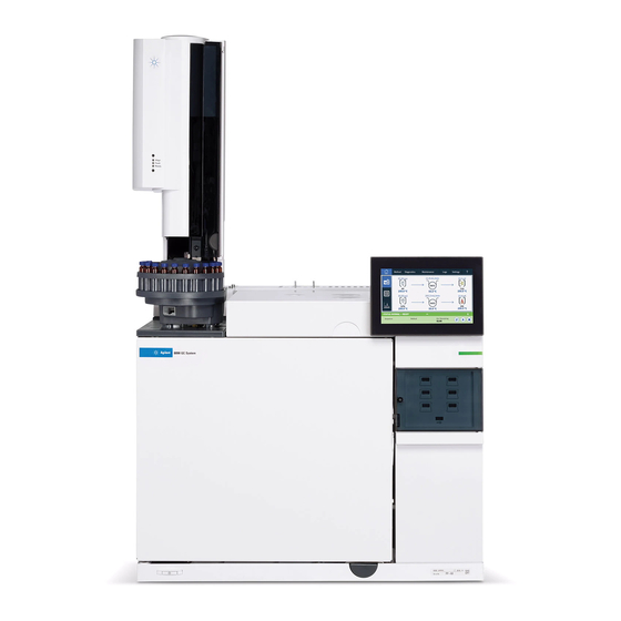
Installing the GC The 8890 GC Detectors Inlets Oven Power switch Touchscreen Figure 1. Front of the 8890 GC Oven exhaust vents Inlet vents Gas supply connections Electronic cable connections EPC cooling intake Power connection Figure 2. Back of the 8890 GC... -
Page 12: Unpacking
Installing the GC Unpacking Be careful when lifting the GC. Because it is heavy, two people should lift it. When moving the WAR N IN G GC, be aware that the back is heavier than the front. 1 Inspect the shipping containers for damage. 2 If a container is damaged or shows signs of stress, do the following: a Notify both the carrier and your local Agilent sales office. -
Page 13: Place The Gc On The Bench
Installing the GC Step 1 Place the GC on the bench The GC requires a bench that can support its weight plus that of other equipment you will use with it. The area must be free of overhanging obstructions that might interfere with autosamplers, or that limit access to the top of the instrument. - Page 14 Installing the GC Oven exhaust deflector Figure 3. Correct position of the oven exhaust deflector The oven exhaust deflector accepts a 10-cm (4 in.) diameter exhaust duct, and adds about 13 cm to the depth of the GC, but this additional depth does not increase the depth required for proper ventilation.
-
Page 15: Verify Line Voltage, Voltage Settings, And Power Cord
“Line voltage” on page 15. The following sections detail the power specifications and requirements for reference. Line voltage Typical GC System - 8890 GC with computer and printer. Use isolated circuits with dedicated grounds for GC and 31-in. (79 cm) -
Page 16: Power Consumption
Installing the GC To protect users, the metal instrument panels and cabinet are grounded through the WAR N IN G three-conductor power line cord in accordance with International Electrotechnical Commission (IEC) requirements. A proper earth ground is required for GC operations. Any interruption of the grounding conductor or disconnection of the power cord could cause a shock that could result in personal injury. -
Page 17: Power Cords Available
Installing the GC Table 1 GC power requirements (continued) Oven Line voltage Frequency Current Power Power outlet current rating Fast Japan: 200 V split phase, +10 to –10% 48-63 Hz 14.8 amps 2950 VA 15 A Fast 220/230/240 V (2)(3) single/split phase, +10 to 48-63 Hz 13.4 / 12.8 / 2950 VA... - Page 18 Installing the GC Table 2 Power cords by country (continued) Part number Country Description Wall termination Plug termination 8120-3997 Denmark, Greenland Power Cord, DK/Greenland, C13, 10 amp AFSNIT 107-2-01 8120-4211 India, South Africa Power Cord, India/S Africa, C13, 10 amp AS 3112 8120-4753 Japan...
- Page 19 Installing the GC Table 2 Power cords by country (continued) Part number Country Description Wall termination Plug termination 8120-6903 Japan Power Cord, Japan, C19, 20 amp NEMA L6-20P 8120-6978 Chile Power Cord, Chile, C13, 10 amp CEI 23-16 8120-8619 Australia Power Cord, Australia, 16 amp AS 3112 Power Cord, GB/HK/SG/MY, C19, 13 amp...
- Page 20 Installing the GC Table 2 Power cords by country (continued) Part number Country Description Wall termination Plug termination 8121-0075 Power Cord, US 240V, C19, 15 amp NEMA L6-15P 8121-0161 Israel Power Cord, Israel, C19, 16 amp Israeli SI32 8121-0675 Argentina Power Cord, Argentina, C19, 20 amp AS 3112 8121-0710...
-
Page 21: Grounding
Installing the GC Table 2 Power cords by country (continued) Part number Country Description Wall termination Plug termination 8121-1787 Brazil Power Cord, Brazil, C19, 16 A, 250V Max IEC 60906-1 8121-1809 Brazil Power Cord, Brazil, C13, 10 A, 250V Max IEC 60906-1 Grounding To protect users, the metal instrument panels and cabinet are grounded through the... -
Page 22: Connect Gc To Lan, Local Computer, Or Tablet
Installing the GC Step 3 Connect GC to LAN, Local Computer, or Tablet If you intend to connect your system to your site’s LAN network, you must have an additional shielded twisted pair network cable (8121-0940). Use a network cable to connect the GC LAN port to your site LAN or directly to a local computer. - Page 23 Installing the GC Figure 5. Simple supported LAN configuration: LAN Switch or hub Agilent is not responsible for connecting to or establishing communication with your site NOTE LAN network. The Agilent representative will test the system’ s ability to communicate on a mini-hub or LAN switch only.
-
Page 24: Connect The Power Cord And Turn On The Gc
Installing the GC Step 4 Connect the power cord and turn on the GC 1 Verify that the power switch is in the Off position. Power Switch Figure 6. Power switch location 2 Plug the power cord into the back of the GC and the power outlet. Attach power cord here Figure 7. -
Page 25: View The System Setup Wizard
Installing the GC Step 5 View the System Setup Wizard The system setup wizard walks through the most important steps needed to install and configure the GC. It provides a way to enter only the critical settings needed to get started quickly, leaving all other configuration settings at their default values. -
Page 26: Configure The Gc Ip Address
Installing the GC Step 6 Configure the GC IP address If you intend to connect your system to your site’s network, each piece of equipment must have a unique IP address assigned to it. For an isolated LAN installation, see Table 3 for typical IP addresses. -
Page 27: Set The Date/Time
Installing the GC Step 7 Set the Date/Time Select Settings > System Settings > Date and Time and set the GC clock. • The Current Time is based on a 24 hour clock. • The time set here is important for the time and date stamps used when collecting data and recording log entries (such as maintenance tasks and errors). -
Page 28: Set The Pressure Units
Installing the GC Step 8 Set the Pressure Units To set the pressure units, select Settings > Configuration > Misc, and select the desired pressure units to use in methods. Installation and First Startup... -
Page 29: Configure Carrier Gas Types
Installing the GC Step 9 Configure Carrier Gas Types Select Settings > Configuration > Inlets and use the dropdown menu to select the Carrier Gas Type connected to the selected inlet. Repeat for any additional inlets installed in your GC. Installation and First Startup... -
Page 30: Connect Gases And Traps
Installing the GC Step 10 Connect Gases and Traps Most of installation involves plumbing gas to tanks, filters, and flow modules. Swagelok fittings are used to make leak-tight connections. If you are not sure how to make a Swagelok connection, see Appendix A, “Making Swagelok Connections”... - Page 31 Installing the GC 3 Install the regulator onto the compressed gas cylinder main fitting. • Check the thread type. Some regulators use left-hand thread fittings. For left-handed threads, the nut will have a groove in it. Groove indicates left-hand thread 4 Purge the air from the regulator by repeating the following procedure 5 times: a Fully close the regulator knob, then open the main tank valve.
-
Page 32: Connect The Tubing To The Gas Source
Installing the GC Secondary gauge Primary gauge Shutoff valve (optional) Main tank valve Regulator knob Swagelok adapter Connect the tubing to the gas source If you need more than 4.5 m (15 feet) of supply tubing to connect to a gas source, use NOTE 1/4-inch tubing with appropriate hardware. -
Page 33: Install Traps
Installing the GC Install traps 1 Determine where you will install the traps in your supply tubing line. Figure 9 shows the recommended trap order for the carrier gas and the recommended locations for On/Off valves. Also see the Site Preparation Guide. Tank valve Two-stage regulator On/Off valve... -
Page 34: Install Aux Epc Module Frits For Your Application
Installing the GC Purge the supply lines for a few minutes before connecting them to the GC flow modules. Be sure to vent uncombusted hydrogen to a fume hood or other safe location. WAR N IN G When two inlets use the same carrier gas, we recommend using a Tee fitting that includes shutoff valves for performing leak tests. - Page 35 Installing the GC • Do not install an external flow restrictor. Installation and First Startup...
-
Page 36: Install Hydrogen Sensor Calibration Gas
Installing the GC Install hydrogen sensor calibration gas If available, install the hydrogen sensor calibration gas. The hydrogen sensor ship kit includes a pressure regulator that installs directly onto the calibration gas cylinder. Agilent also provides sufficient copper tubing and hardware to connect the pressure regulator to the hydrogen sensor assembly calibration gas input fitting. - Page 37 Installing the GC 4 Connect the calibration gas cylinder output tubing to the hydrogen sensor module. • Use the tubing, nuts, and ferrules provided in the hydrogen sensor kit. • See the figure under step 5 Install the calibration gas cylinder into the stand and secure using the screw. 6 Turn on the supply pressure at the pressure regulator.
-
Page 38: Leak Test All Connections And Set Source Pressures
Installing the GC Step 11 Leak test all connections and set source pressures Liquid leak detectors, such as soapy water, are not recommended, especially in areas where cleanliness is very important. If there is a leak, these liquids can contaminate the plumbing and affect your analyses. - Page 39 Installing the GC Figure 11. Locations to check for leaks 5 Correct leaks by tightening the connections and then retest the connections. Continue tightening until all connections are leak-free. Installation and First Startup...
-
Page 40: Set Source Gas Pressures
Installing the GC Set source gas pressures The pressure set at a tank regulator depends on these factors: • The inlet pressure needed to achieve the highest column flow rate required by your method. The pressure/flow relationship depends on the column or device involved. The best way to address this is to begin at a moderate pressure level and adjust upward as needed. -
Page 41: Install Inlet Checkout Parts
Installing the GC Step 12 Install inlet checkout parts If using a split/splitless or multimode inlet, install the liner and O-ring needed for checkout. See the Operation manual, and the procedures listed in Maintaining Your GC. If installing a GC/MS system, refer to the GC/MS installation manuals for the correct inlet hardware to install, as needed. -
Page 42: Install Als, If Ordered
Installing the GC Step 13 Install ALS, if ordered If installing an ALS, install it now. Refer to its instructions. Prepare the sampler for checkout. See the checkout procedures and information in the Operation Manual. 1 Prepare a 2-mL screw-top sample vial with checkout sample. 2 Prepare 4-mL waste vials and place them into the turret. -
Page 43: Configuring Gc-Msd Communications
Installing the GC Step 14 Configuring GC-MSD communications If connected to an MSD such as 5977A or 7000C/D, use the GC touchscreen to identify the connected MSD’s IP address and to select the part information (for example, source type, and pump type). -
Page 44: Connect The External Cables
Installing the GC Step 15 Connect the external cables In addition to the LAN cable as referenced in “Connect GC to LAN, Local Computer, or Tablet” on page 22, other cables may be installed for control of the GC’s automatic liquid sampler (ALS), connecting signal output to integrators, synchronizing the start and end of a run between various instruments, sensing conditions external to the GC, and controlling devices external to the GC. -
Page 45: Connecting Cables
Installing the GC EVENT connector This connector provides two passive contact closures and two 24-volt outputs for controlling external devices. The outputs are controlled by valve drivers 5 through 8. BCD input connector This connector provides two control relays and a BCD input for a stream selection valve or a BCD generating device. - Page 46 G1530-61200 system (for example, GC/HS/MSD or GC/Thermal Desorber/MSD) GC / TMS-9800/ MS or MSD system Y-Cable, remote start/stop G1530-61200 Interface cable for Agilent 6890/7890/8890 to P&T 14-6689-086 Integrators 3395B/3396C Integrator Remote, 9 pin/15 pin 03396-61010 Analog, 2 m, 6 pin...
-
Page 47: Gc / Ms / Agilent Data System / Als
Installing the GC Table 9 Cabling for other instruments in a 8890 Series GC system Instrument 1 Instrument 2 Type of cable Part number Mass Selective Detector Purge & trap, thermal Splitter (“Y”) cable for remote G1530-61200 desorber, or headspace... -
Page 48: Vent Ecd Or Uncombusted Hydrogen To A Fume Hood
Installing the GC Step 16 Vent ECD or uncombusted hydrogen to a fume hood If using a ECD, or if using hydrogen carrier gas that will be uncombusted, you must either safely vent the exhaust or operate the GC inside a fume hood. For example, if using hydrogen carrier gas the GC would vent uncombusted hydrogen from a thermal conductivity detector (TCD) and from the inlet split vent and septum purge vent. -
Page 49: Connect Cryogenic Cooling (If Present)
Installing the GC Step 17 Connect cryogenic cooling (if present) Cryogenic cooling allows you to cool the oven or inlet, including cooling to setpoints below ambient temperature. A solenoid valve controls the flow of coolant to the inlet or oven. The oven can use either liquid carbon dioxide (CO ) or liquid nitrogen (N ) as a coolant. -
Page 50: Connecting Liquid Nitrogen
Installing the GC Cryo inlets Figure 13. Location of cryogenic cooling valve 2 Connect the supply tubing to the liquid CO tank outlet with the fitting recommended by the supplier. 3 Use a Swagelok fitting to connect the supply tubing to the cryogenic valve inlet. Connecting liquid nitrogen Materials needed •... -
Page 51: Connecting Air To The Multimode Inlet
Installing the GC Cryo inlets Figure 14. cryogenic cooling valve connections 3 Connect the supply tubing to the liquid N tank outlet with the fitting recommended by the supplier. 4 Use a Swagelok fitting to connect the supply tubing to the cryogenic valve inlet. Connecting air to the multimode inlet The multimode inlet can also use compressed air cooling with the liquid N inlet cooling... - Page 52 Installing the GC Procedure 1 Locate the input fitting for inlet coolant on the rear of the GC. Prepare enough tubing to reach from the supply to this outlet. 2 Connect the supply tubing to the air supply outlet with the fitting recommended by the supplier.
-
Page 53: Connect Valve Actuator Air (If Present)
Installing the GC Step 18 Connect valve actuator air (if present) Valves are driven by air actuators. Valves should have a dedicated air source; they cannot share detector air supplies. Do not share air between a detector and valves. C AU T I O N Valves can use nitrogen as an alternate supply. -
Page 54: Configure Headspace Communications
Installing the GC Step 19 Configure Headspace Communications The 7697 headspace sampler can be configured to communicate with the connected GC. This feature requires a HS with firmware A.01.06 (or greater). With communications configured, the HS knows GC method timings and programs, and can synchronize with the GC clock and follow the GC instrument schedule. -
Page 55: Configure The Checkout Column
Installing the GC Step 20 Configure the checkout column You must configure the consumable items (such as the checkout column). If your checkout column has a Smart ID Key, Insert the key into one of the six Smart ID key slots on the front of the GC. - Page 56 Installing the GC 7 Select the Thermal zone. In most cases this will be GC oven but you may have an MSD transfer line heated by an auxiliary zone, valves in a separately-heated valve box or other configurations. 8 Press Apply This completes configuration for a single capillary column.
-
Page 57: Install The Checkout Column
Installing the GC Step 21 Install the checkout column A capillary column was shipped with the GC to be used to confirm proper operation. Agilent suggests that it be used only for that purpose. Before use, the column must be conditioned to remove any contaminants. 1 Locate the installation instructions for the column, inlet, and detector you will use. - Page 58 Installing the GC 6 Set the oven temperature and inlet flow conditions specified for conditioning the column. Select Method to access current GC temperatures and flows. • Set the oven temperature to 20 °C higher than the highest checkout method temperature (do not exceed the column maximum temperature).
-
Page 59: Transfer The Checkout Sample To A Screw-Top Sample Vial
Installing the GC Step 22 Transfer the checkout sample to a screw-top sample vial 1 The checkout sample is contained in sealed glass vials. Wrap a piece of cloth or a paper towel around the vial to protect your fingers and snap the top off. 2 Use a pipette to transfer the sample to a 2-mL screw-top vial. -
Page 60: When The System Stabilizes, Run One Injection
Installing the GC Step 23 When the system stabilizes, run one injection Perform the checkout procedure as described in the Operation Manual. 1 Enter the parameters for the checkout procedure. • If using an Agilent data system, use it to create a checkout method. •... -
Page 61: Prepare For The Next Analysis
Installing the GC Step 24 Prepare for the Next Analysis After evaluating the GC under the checkout conditions, installation checkout is complete. The next step is to prepare the GC for your next analysis. Be sure to cool the GC before making changes. - Page 62 Installing the GC Installation and First Startup...
-
Page 63: A Making Swagelok Connections
Making Swagelok Connections Making Swagelok Connections 64 Using a Swagelok Tee 67 The gas supply tubing is attached with Swagelok fittings. If you are not familiar with Swagelok connections, review the following procedures. Installation and First Startup... -
Page 64: Making Swagelok Connections
Making Swagelok Connections Making Swagelok Connections Objective To make a tubing connection that does not leak and that can be taken apart without damaging the fitting. Materials needed • 1/8-inch (or 1/4-inch, if used) preconditioned copper tubing • 1/8-inch (or 1/4-inch, if used) Swagelok nuts •... - Page 65 Making Swagelok Connections Front ferrule Insert tubing fully Back ferrule Withdraw tubing 1-2 mm Tighten nut Figure 17. Insert the tubing 5 Finger-tighten the nut. 6 Mark the nut with a pencil line. See Figure Pencil line Figure 18. Marking the fitting 7 For 1/8-inch Swagelok fittings, use a pair of wrenches to tighten the fitting 3/4 of a turn.
- Page 66 Making Swagelok Connections 9 Both correctly and incorrectly swaged connections are shown in Figure 20. Note that the end of the tubing in a correctly swaged fitting is not crushed and does not interfere with the action of the ferrules. Figure 20.
-
Page 67: Using A Swagelok Tee
Making Swagelok Connections Using a Swagelok Tee To supply gas from a single source to more than one input, use a Swagelok Tee. Do not combine valve actuator air with flame ionization air. The valve action will cause major NOTE upsets in the detector signal. - Page 68 Making Swagelok Connections Installation and First Startup...
-
Page 69: B Cabling Diagrams And Remote Start/Stop
Cabling Diagrams and Remote Start/Stop Cabling Diagrams and Remote Start/Stop Using the Remote Start/Stop Cable 70 Multi-instrument Cabling Examples 73 Cable Diagrams 77 This section lists cabling requirements and connection diagrams that apply to less common or specialized GC installations. Installation and First Startup... -
Page 70: Using The Remote Start/Stop Cable
Cabling Diagrams and Remote Start/Stop Using the Remote Start/Stop Cable Remote start/stop is used to synchronize two or more instruments. For example, you might Start Stop connect an integrator and the GC so that the buttons on either instrument control both of them. - Page 71 Receiver is any sequence controller. Start (Low True) Request to start run/timetable. Receiver is any module performing runtime-controlled activities. The 8890 Series GC requires a pulse duration of at least 500 micro-seconds to sense a start from an external device.
- Page 72 Cabling Diagrams and Remote Start/Stop APG Remote timing diagram Prepare H Start Stop Ready Installation and First Startup...
-
Page 73: Multi-Instrument Cabling Examples
Cabling Diagrams and Remote Start/Stop Multi-instrument Cabling Examples GC / ALS / Non-Agilent Data System GC/ALS 1. APG Remote Cable, 2. External event cable, G1530-60930 8 pin/spade lugs, G1530-60590 Number Part number and description G1530-60930, General use APG remote cable, 9-pin male/spade lug (0.5m) G1530-60590, External event cable, 8-pin/spade lugs 35900-60670 APG remote... -
Page 74: Gc / 3395A/3396B Integrator / Als
Cabling Diagrams and Remote Start/Stop GC / 3395A/3396B Integrator / ALS GC/ALS 1. APG Remote Cable, 2. Analog cable, 2-m, 6 pin, 03396-61010 G1530-60570 Number Part number and description 03396-61010, 2-m APG remote cable, 9-pin/15-pin G1530-60570, 2-m Analog cable, 6-pin GC / 3396C Integrator / ALS GC/ALS 1. -
Page 75: Example: Using A Y-Cable In A Setup (Gc/Msd/Data System/Headspace Sampler)
Cabling Diagrams and Remote Start/Stop Example: Using a Y-Cable in a setup (GC/MSD/Data System/Headspace Sampler) LAN switch or hub 1. LAN cable 8121-0940 1. LAN cable 1. LAN cable 1. LAN cable 8121-0940 8121-0940 8121-0940 GC/ALS Computer 2. APG Remote Y-Cable, G1530-61200 Number Part number and description... -
Page 76: Gc / External Events (Unspecified, Non-Agilent Instrument)
Cabling Diagrams and Remote Start/Stop GC / External Events (unspecified, non-Agilent instrument) 1. External event cable, 8 pin/spade lugs, G1530-60590 GC/ALS Number Part number and description G1530-60590, External events cable, 8-pin/spade lugs Connector Signal name Maximum rating Wire color Corresponds to valve # 24 volt control output 24 volt output 1 150 mA output... -
Page 77: Cable Diagrams
Cabling Diagrams and Remote Start/Stop Cable Diagrams Analog signal cable, general use, G1530-60560 Connects GC signal outputs to non-Agilent products. Also used for the Analog Input Board (AIB). G1530-60560 Connector 1 Connector 2 The pin assignments for the general use analog out cable are listed in Table Table 11 Analog cable, general use, output connections Connector 1... -
Page 78: Agilent Analog Signal Cable, G1530-60570
Cabling Diagrams and Remote Start/Stop Agilent analog signal cable, G1530-60570 Analog out This cable connects an port to an external data system. Both 0 to 1 volt and 0 to 10 volts are provided. Connects both GC signal outputs to Agilent 3395B/3396C integrators, and the 35900 A/D. -
Page 79: Agilent Apg Remote Start/Stop Cable, 03396-61010
Cabling Diagrams and Remote Start/Stop Agilent APG remote start/stop cable, 03396-61010 Synchronizes the GC with an Agilent integrator. Additional cables may be used to add more instruments (up to 10 total). Figure 23. Remote start/stop cable, GC to Agilent integrator Agilent APG remote start/stop cable, G1530-60930 Synchronizes the GC with another Agilent instrument. -
Page 80: Agilent Remote Start/Stop Y-Cable, G1530-61200
Cabling Diagrams and Remote Start/Stop Agilent remote start/stop Y-cable, G1530-61200 Synchronizes the GC with another 2 Agilent instruments. Figure 25. Remote start/stop cable, GC to Agilent instrument BCD cable, G1530-60590 The BCD cable connector has eight passive inputs that sense total binary-coded decimal levels. - Page 81 Cabling Diagrams and Remote Start/Stop Table 14 BCD cable connections (continued) Connector 1 Pin Connector 2 Pin Ribbon Cable Wire Color Orange Yellow Green Blue Violet Gray White 2, 8 Black Brown Orange Yellow Green Blue Violet Gray White Black Brown Orange Yellow...
-
Page 82: External Event Cable, G1530-60590
Cabling Diagrams and Remote Start/Stop External event cable, G1530-60590 Apply label G1580-87200 Wire terminations The external event cable has two passive relay contact closures with two 24-volt control outputs. Devices connected to the passive contact closures must be connected to their own power sources. -
Page 83: External Valve Cable, G1580-60710
Cabling Diagrams and Remote Start/Stop External valve cable, G1580-60710 Supplies power for certain valve applications. Connector 1 pin Wire color Connector and pin Function Yellow V5 pin 1 24 V, 150 mA max. Black V6 pin 1 24 V, 150 mA max. V5 pin 2 Ground White... - Page 84 Cabling Diagrams and Remote Start/Stop Connector 1 Connector 2 Connector 3 Connector 1 pin Wire color Connector and pin Function Yellow Black White Connector 3 pin 1 Ground Orange Connector 2 pin 1 Contact closure 1, 48 V AC/DC, 250 mA Green Connector 3 pin 3 Contact closure 1...
- Page 85 This page intentionally left blank. Installation and First Startup...
- Page 86 Agilent Technologies, Inc. 2018 First edition, December 2018 *G3540-90013* G3540-90013...