
Related Manuals for Gravely Pro-Stance 99410000-1948FL


Summary of Contents for Gravely Pro-Stance 99410000-1948FL
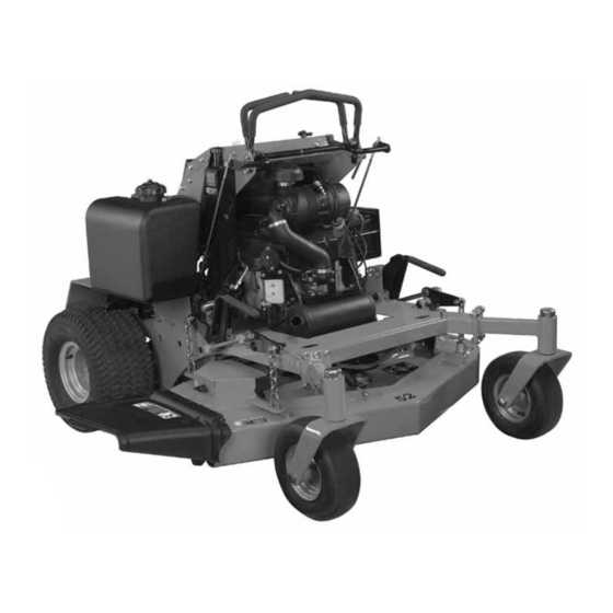
- Page 1 Pro-Stance ™ Owner/Operator Manual Models 99410000 – 1948FL 99410300 – 2352FL ENGLISH ESPAÑOL 00876400A 5/07 Printed in USA...
-
Page 2: Table Of Contents
PRODUCT REGRISTRATION Before operation of unit, carefully and completely read your The Gravely dealer must register the product at the time of manuals. The contents will provide you with an understanding of purchase. Registering the product will help the company process safety instructions and controls during normal operation and warranty claims or contact you with the latest service information. -
Page 3: Safety
SAFETY PRACTICES AND LAWS WARNING: This cutting machine is capable of Practice usual and customary safe working precautions, for the amputating hands and feet and throwing objects. Failure benefit of yourself and others. Understand and follow all safety to observe the safety instructions in the manuals and on messages. - Page 4 NOTE: Tampering with emission controls and components by unauthorized personnel may result in severe fines or penalties. Emission controls and components can only be adjusted by EPA and/or CARB authorized service centers. Contact your Gravely Equipment Retailer concerning emission controls and component questions.
- Page 5 • Slow down and use caution when making turns and when Checking Mowing Area changing directions on slopes. • Evaluate the terrain to determine what accessories and • Never raise deck with the blades running. attachments are needed to properly and safely perform the •...
- Page 6 Protect Children • Keep all movement on slopes slow and gradual. Do not make sudden changes in speed or direction, which could cause the machine to roll over. • Use extra care while operating machine with grass catchers or other attachments, they can affect stability of the machine. Do not use on steep slopes.
- Page 7 Maintenance and Storage • Check fuel lines, tank, cap, and fittings frequently for cracks or leaks. Replace if necessary. • Never operate machine in a closed area where dangerous carbon monoxide fumes can collect. Tire Safety • Disengage drives, lower implement, lock parking brake, stop Explosive separation of a tire and rim parts can cause serious injury engine and remove key or disconnect spark plug (for gas or death:...
-
Page 8: Controls And Features
• Never fill containers inside a vehicle or on a truck or trailer bed • For gasoline engines, do not use gas with methanol. Methanol with a plastic liner. Always place containers on the ground is harmful to your health and to the environment. away from your vehicle before fueling. - Page 9 Mower Deck Controls 3. Step off operator’s platform to dismount machine. 4. Keep operator’s platform and suspension springs clean and free of debris. Raising and Lowering Thigh Pad 1. Park machine safely. (See Parking Safely in the SAFETY section.) MX20093 A-Mower Deck Lift Levers B-Height-of-Cut (HOC) Pin Miscellaneous Controls...
- Page 10 Leveling Mower Deck Adjusting Level (Side-to-Side) NOTE: When adjusting U-bolts, maintain a minimum clearance of CAUTION: Avoid injury! Rotating blades are dangerous. 3 mm (1/8 in.) between mower deck and stop pads. Before adjusting or servicing mower: Disconnect spark plug wire(s) or battery negative (-) cable to prevent engine from starting accidently.
- Page 11 5. If the front-to-rear level is not within the tolerance, an adjustment is necessary. Adjusting Level (Front-to-Rear) IMPORTANT: Avoid damage: Adjust the left and right deck lift assist rods equally. NOTE: Adjust side-to-side mower level before adjusting front-to-rear level. Adjust both sides of the mower deck equally. All lift chains must remain taut.
- Page 12 The safety systems installed on your machine should be checked Testing the Park Brake before each machine use. Be sure you have read the machine operator manual and are completely familiar with the operation of the machine before performing these safety system checks. Use the following checkout procedures to check for normal operation of machine.
- Page 13 MX20091 • Hour meter (A) shows number of hours the machine has been operated. • Use hour meter and SERVICE INTERVAL section to determine when machine needs service. Using the Motion Control Levers The functions of the motion control levers are: CAUTION: Avoid injury! Learn use of the motion control levers and practice at half throttle until becoming proficient and comfortable with the operation of the...
- Page 14 5. To stop motion, move both motion control levers forward or Gentle Right Turn: rearward until the machine comes to a stop. NOTE: The motion control linkages are adjustable. If adjustment is required, see Checking and Adjusting Motion Control Linkages in the SERVICE TRANSMISSION section.
- Page 15 Starting Engine CAUTION: Avoid injury! Engine exhaust fumes contain carbon monoxide and can cause serious illness or death. Move the machine to an outside area before running the engine. Do not run an engine in an enclosed area without adequate ventilation. •...
-
Page 16: Maintenance Schedule
NOTE: The pumps (A) are located in the back of the machine, Mowing Tips behind the rear shield (B). • Mow grass with throttle lever in the full fast position. • Cut grass when it is dry. • Keep mower deck and discharge chute clean. •... - Page 17 Every 40 Hours • Check air pressure in tires. • Check wheel bolt torque. • Check and adjust park brake. • Change engine oil and filter. • Check foam and paper air cleaner elements. • Clean engine shrouds as needed. •...
- Page 18 Lubricating Mower Deck Spindles SERVICE ENGINE Avoid Fumes CAUTION: Avoid injury! Engine exhaust fumes contain carbon monoxide and can cause serious illness or death. Move the machine to an outside area before running the engine. Do not run an engine in an enclosed area without adequate ventilation.
- Page 19 IMPORTANT: Avoid Damage! To prevent extensive engine wear or damage, always maintain the proper engine oil level. Never operate the engine with the oil level below the add mark or over the full mark. 6. Remove dipstick and check oil level on dipstick. Oil must be between the ADD and FULL marks.
- Page 20 Keep air intake screens and engine cooling fins clear of debris to Replacing Fuel Filter ensure proper cooling. See the engine manufacturer’s owner’s manual provided with your machine for the complete procedure. CAUTION: Avoid injury! Fuel vapors are explosive and flammable: Checking and Cleaning Air Filter Elements •...
-
Page 21: Service And Adjustments
SERVICE AND ADJUSTMENTS IMPORTANT: Avoid Damage! Contamination of hydraulic fluid WARNING: AVOID INJURY. Read and understand entire could cause transmission damage or failure. Do not open oil Safety section before proceeding. reservoir cap unless absolutely necessary. Severe or unusual conditions may require a more frequent service interval. - Page 22 Cleaning Hydraulic Oil Pump Cooling Fins 3. Remove rear shield (B). CAUTION: Avoid injury! Compressed air can cause debris to fly a long distance. • Clear work area of bystanders. • Wear eye protection when using compressed air for cleaning purposes. •...
- Page 23 6. Remove traction drive belt (E). Installing Traction Drive Belt: NOTE: Install the traction drive belt (E) in front of anchor cap screw (F). MX20109 2. Rotate speed control bar (A) to full forward position. 3. With engine off, move motion control levers (B) until they MX20168 contact the speed control bar (A).
- Page 24 MX20161 Picture Note: Side frame removed for picture clarity. 8. Slightly loosen cap screw (A) to allow rotation of neutral return MX20109 plate. 4. Drive machine forward, pushing both control levers (A) all the • If wheel is rotating forward, rotate neutral return plate way to speed control bar (B).
- Page 25 3. Tighten lock lever (B). • A properly adjusted park brake must prevent the drive wheels from turning. Adjusting Reverse Speed: • If the drive wheels turn, a brake adjustment will be necessary. 1. Park machine safely. (See Parking Safely in the SAFETY Adjusting Park Brake: section.) 2.
- Page 26 Installing Mower Deck Shield: • To release tension from spring: Loosen jam nut (B). Turn nut (A) counterclockwise. Tighten jam nut (B). 1. Insert rear of shield (B) under tabs on frame and lower shield into position. Replacing Mower Deck Drive Belt 2.
- Page 27 Disconnect battery or remove spark plug wire before making repairs. IMPORTANT: Avoid Damage! When replacing mower blades, always use genuine Gravely Service Parts. NOTE: Only replace blades. Never straighten or weld them. MX20118 Checking Mower Blades 3.
- Page 28 Replacing Mower Blades Balancing Blades CAUTION: Avoid injury! Mower blades are sharp. Always wear gloves when handling mower blades or working near blades. Clean blade. 1. Remove blade bolt (A), three 1/4 in. washers (C) and blade M61524 (B). 2. Put blade on nail in a vise. Turn blade to horizontal position. 2.
- Page 29 CAUTION: Avoid injury! Battery electrolyte contains sulfuric acid. It is poisonous and can cause serious burns: • Wear eye protection and gloves. • Keep skin protected. • If electrolyte is swallowed, get medical attention immediately. • If electrolyte is splashed into eyes, flush immediately with water for 15-30 minutes and get medical attention.
- Page 30 • Install new 20 Amp fuse in socket. • Install socket with fuse in cover. Ensure that plastic tab of fuse holder is securely fastened to fuse socket. Service Miscellaneous Using Proper Fuel Use regular grade unleaded fuel with an octane rating of 87 octane or higher.
- Page 31 1. Park machine safely. (See Parking Safely in the SAFETY Removing and Installing Front Caster section.) Wheels 2. Allow engine to cool. 3. Remove any trash from area around fuel tank cap. Removing: 4. Remove fuel tank cap slowly to allow any pressure built up in 1.
- Page 32 Checking Tire Pressure CAUTION: Avoid injury! Explosive separation of tire and rim parts is possible when they are serviced incorrectly: Do not attempt to mount a tire without the proper equipment and experience to perform the job. Do not inflate the tires above the recommended pressure. Do not weld or heat a wheel and tire assembly.
-
Page 33: Troubleshooting
Cleaning and Repairing Metal Surfaces 2. Use automotive polishing compound to remove surface scratches. Cleaning: 3. Apply wax to entire surface. Follow automotive practices to care for your vehicle painted metal Repairing Deep Scratches (bare metal or primer surfaces. Use a high-quality automotive wax regularly to maintain showing): the factory look of your vehicle’s painted surfaces. - Page 34 Electrical System Check Check Engine Knocks • Engine oil level low. • Reduce load. (Slower ground Starter Will Not Work • Blown fuse. speed.) • Park brake switch is faulty. • Fuel is bad. Fill tank with fresh • Loose or corroded battery fuel, correct octane.
- Page 35 Park Brake Check Check Mower Mows Unevenly • Mower deck not properly leveled. Park Brake Not Working • Park brake out of adjustment – • Ground speed too fast for Correctly adjust linkage. conditions. Steering • Run engine at fast throttle. •...
-
Page 36: Storage
STORAGE Storing Safety 3. Clean debris from engine air intake screen. On gas engines: • Remove spark plugs. Put 30 mL (1 oz) of clean engine oil in CAUTION: Avoid injury! Fuel vapors are explosive and cylinders. flammable. Engine exhaust fumes contain carbon monoxide and can cause serious illness or death: •... -
Page 37: Assembly
ASSEMBLY Connect Battery WARNING: AVOID INJURY. Read and understand entire CAUTION: Avoid injury! Prevent Battery Explosions: Safety section before proceeding. Keep sparks, lighted matches, and open flame away from the top of battery. Battery gas can explode. Check Hydraulic Oil Level Never check battery charge by placing a metal object across the posts. -
Page 38: Specifications
SPECIFICATIONS Model Number 994100 994103 Model Pro-Stance 1948FL Pro-Stance 2352FL NOTE: See engine manufacturer’s owner’s manual Engine provided with your machine for engine specifications. Engine Kawasaki Kawasaki Engine Model Number FH580V FH680V Engine Power – hp (kW) at 19 (14.2) 23 (17.2) Maximum RPM Air Cooled... -
Page 39: Service Parts
Gravely Quality Continues with Quality Service SERVICE PARTS Gravely provides a process to handle your questions or problems, should they arise, to ensure that product quality continues with your Recommended Lubricants authorized Gravely dealer’s parts and service support. Engine Oil – See Applicable Engine Manual... - Page 40 Wiring Schematics MX20146 GB - 40...
- Page 41 Service Miscellaneous Hydraulic Schematics MX20151 J. Right Hydrostatic Pump Assembly K. Right Wheel Motor A. Left Hydrostatic Pump Assembly L. Inlet Filter B. Pump Block M. Hydraulic Reservoir C. Charge Pump D. System Charge Check Shock Valve (Reverse) E. Manual Bypass F.
-
Page 42: Warranty
1000 hours of use, whichever comes first. An upon examination by the Ariens Company to be defective or authorized Gravely dealer will repair any defect in material or worn out. Replacements will be supplied free of charge. - Page 43 • Warranty service must be performed by a respective Ariens or Gravely authorized service representative. • Parts that are not genuine Ariens or Gravely brand service parts are not covered by this warranty. • To find an Ariens or Gravely authorized service representative, contact Ariens at: •...
- Page 44 GRAVELY 655 West Ryan Street Brillion, WI 54110-0157 920-756-2141 Fax 920-756-2407 www.gravely.com...