
Related Manuals for Delta HPP-1K5A01KAT


Summary of Contents for Delta HPP-1K5A01KAT
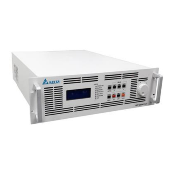
- Page 1 User Manual PULSED DC Power Supply Continuous 325 – 1000VDC Model: HPP-1K5A01KAT A Version: Rev.S.00...
- Page 2 This product Delta “HPP-1K5A01KAT” Model is been warranted against defect in material and workmanship for a period of “1” year after date of shipment. Delta agrees to repair or replace the fault unit free-of-charge which fails to perform with specification and under normal use during this period.
-
Page 3: Table Of Contents
INDEX ............... Chapter 1: Safety and Standard ································································· 1 1.1. Important Safety Information ··········································································· 1 1.2. Safety and Warning Symbols ·········································································· 1 1.3. Electromagnetic Compatibility Directives and Standard ········································· 2 1.4. Industry Guideline ························································································ 2 Chapter 2: Introduction ············································································· 3 2.1. -
Page 4: Chapter1: Safety And Standard
1.1. Important Safety Information To keep your safety from hazardous and fatal circumstance, please read and realize the content of this manual before installing and operating Delta “HPP-series” power supply. 1.2. Safety and Warning Symbols The following advisory symbols as shown in Table 1.1 will be used in the manual for different level of warning. -
Page 5: Electromagnetic Compatibility Directives And Standard
Heavy object: Two persons lifting are recommended to avoid muscle strain or back injuries. 1.3. Electromagnetic Compatibility Directives and Standard Disturbance Characteristic: EN55011 - CRSP11 Class A, Group 1 (>20kVA) General Immunity Standard for Industry: EN 61000-6-2 Safety Requirement: IEC-61010-1 (CE and UL certification) 1.4. -
Page 6: Chapter 2: Introduction
Asymmetric pulsing output makes the arc happening reduced dramatically. With High-speed MCU based arc detection, Delta power could achieve 1 micro-sec arc detection time. As soon as the arc is detected, the output will be reversed to positive to reduce arc energy approximately 5 microseconds. -
Page 7: Key Feature
Adaptable Fan Front Panel Display Isolated Remote Interfaces Figure 3.1 System Block Diagram of Delta “HPP-1K5A01KAT” Table 3.1 Detail Description for Block Diagram Three phase main voltage is applied while breaker is closed. After Taipei rectifier PFC, soft start mechanism suppresses inrush current to prevent any damage. - Page 8 The AUX power provides low voltage source to supply the Vcc of Housekeeping supplies analog OPA, main controller, MCU, fan and LCD display. The MCU is responsible for controlling the power supply status and Control Circuit providing status information to the operator through all interfaces. Control panel shows operating mode, command level, feedback values, set up Arc processing, process control, interface setup, Front Panel Display...
-
Page 9: Electrical Specification
3.2. Electrical Specification Table 3.2 Electrical Specification Item Specification Condition Input Voltage 208V ± 10% (Three Phase) 50 to 60Hz Input Current (Per Phase) 5.5A nominal per phase Rated output power Maximum Output Power 1.5kW Measured at the DC output Output Voltage Range 131V to 1000V... - Page 10 3.3. Reverse Time as a Function of Voltage Limit (V-Limit) V-Limit(in Volts) Corresponding Reverse Time μs 0-325 μs μs μs μs μs μs μs μs μs μs μs μs μs μs μs μs μs μs μs μs μs μs μs μs μs μs...
- Page 11 μs μs μs μs μs μs μs μs μs μs μs μs μs μs μs μs μs μs μs μs μs μs μs μs μs μs μs μs μs μs μs μs μs μs μs μs μs μs μs μs μs μs μs...
- Page 12 μs μs μs μs μs μs μs μs μs μs μs μs μs μs μs μs μs μs μs μs μs μs μs μs μs μs μs μs μs μs μs μs μs μs μs μs μs μs μs μs μs μs μs...
- Page 13 μs μs μs μs μs μs 1000 Reverse Time Given a Self-Run Frequency Requested Actual Pulse Duty Cycle Duty Cycle Frequency Frequency Reversal (min%) (max%) (kHz) (kHz) Time Reverse/ Reverse/ Maximum Period Period (μs) 15.004 29.985 35.026 45.045 44.6 54.945 44.5 60.06 44.4...
- Page 14 69.93 44.8 74.906 44.9 44.8 85.106 44.3 90.09 44.1 94.787 3.79 44.5 105.263 4.21 44.2 109.89 114.943 44.8 119.76 4.79 44.3 129.87 5.19 44.2 135.135 5.41 44.6 139.86 5.59 44.8 144.928 44.9 150.376 6.02 43.6 155.039 44.8 165.289 6.61 44.6 169.492 6.78 44.1...
- Page 15 289.855 11.59 37.7 294.118 11.76 38.2 298.507 11.94 38.8 303.03 12.12 39.4 307.692 12.31 312.5 12.5 37.5 317.46 12.7 38.1 322.581 12.9 38.7 327.869 13.11 39.3 333.333 13.33 338.983 13.56 37.3 344.828 13.79 37.9 350.877 14.04 38.6 355.877 14.2 35.5 360.878 14.4 365.788...
- Page 16 1333Ω Figure 3.3 Curve of Output Impedance Characteristic For Delta “HPP-1K5A01KAT” power supply, the maximum output voltage and current level are 1000 V and 4.62 A (Measured at the DC output). The output characteristic is as the figures above. If the operation point is below 325V, the power supply can provide at most 4.62 A, if the operation is more than 325V, the maximum output current will decrease to 1.5 A within the output voltage...
-
Page 17: Arc Suppression Specification
3.4. Arc Suppression Specification Figure 3.4 shows the waveforms and key parameters under arc condition, and Table 3.3 indicates the arc energy and adjustable parameters for user. As soon as the arc is detected by arc voltage detection within 1 micro sec, power ON delay after a micro ARC will be approximately 5 microseconds. -
Page 18: Ignition Profile
3.5. Ignition Profile Figure 3.5 shows the waveform of output voltage under Ignition condition. When power ON with ignition function enabled, the output voltage will rise from 0V to ignition voltage within 10ms. Then the voltage will stay on ignition voltage for 100ms and fall to 1000V for 900ms. This profile will repeat every 1s. -
Page 19: Mechanical Specification
1 to 15000 kWh reaches the setting of kWh. 3.7. Mechanical Specification The outward appearance, cooling specification for minimum CFM Requirement, and I/O ports of Delta “HPP-1K5A01KAT” sputtering power supply are described as below: Table 3.4 Mechanical Specification Item Description 482.6(W)x132.5(H)x560(L)mm... - Page 20 Figure 3.7 Air Flow Schematic Diagram Delta “HPP-1K5A01KAT” sputtering power supply is the forced air cooling type. Please keep enough space for air flow cooling capability when it is installing to the cabinet. Air inlet on the front panel and air outlet on the rear panel is shown in figure 3.7.
-
Page 21: Environment Specification
3.8. Environment Specification Table 3.6 Climatic Specification Item Temperature Relative Humidity Air Pressure 80kPa to 106kPa 0˚C to 40˚C 10% to 90% RH (Non- Operating (approximately 2000m (32˚F to 104˚F) condensing) above sea level) 80kPa to 106kPa -25˚C to 55˚C Storage 10% to 95% RH (approximately 2000m... -
Page 22: Chapter 4: System Protection Mechanism
Chapter 4: System Protection Mechanism 4.1. Input Breaker The function of this switch is to prevent over current at input side from any malfunction happening and simultaneously provide a manual switch for user to turn off the power supply. 4.2. Protection by MCU (A: Auto Recovery, L: Latch) Table 4.1 Definition and description of MCU protection Alarm Condition Code... -
Page 23: Chapter 5: Installation
Chapter 5: Installation Delta “HPP-1K5A01KAT” power supply is a high voltage power supply. Please read this manual carefully and follow the instruction before installation and operation, otherwise an electric shock or a fatal accident might be caused. Chamber Shielding Figure 5.1 Installation diagram ... -
Page 24: Cooling Requirements
5.1. Cooling Requirements For the HPP-1K5A01KAT A supply to be sufficiently cooled, the cabinet must be set up to:. 1. Bring in coolant air of the correct temperature(40 ˚C maximum) 2. Distribute coolant air to the power supplies 3. Prevent air exhausted from the cabinet from circulating back and becoming input air 4. -
Page 25: Grounding
5.3. Grounding For your convenience, the rear panel of the HPP-1K5A01KAT supply features three equipotential ground screw: three M6 screw. These are indicated on the rear panel by a ground symbol.See figure 6.2 for more information. -
Page 26: Chapter 6: Interface
Chapter 6: Interface 6.1. Front Panel The functions for several buttons on the front panel are described on Table 6.1 Table 6.1 Function description of front panel 1. Press the button to change all of adaptive parameters. “Enter” Button 2. Press the button to enter the next layer while in menu screen. 1. - Page 27 Display Panel LEDs POWER ON Lights green when input power is on OUTPUT Lights green if output power is on SETPOINT Lights green if the Pulsed DC power supply is operating within set point; accuracy is within 0.4% of full scale or 2% of set point, whichever is greater INTERLOCK Lights green if all interlock conditions have been met BUS FAULT...
-
Page 28: Rear Panel
6.2. Rear Panel 1. GND terminal is for chamber grounding, and earth grounding should be performed for safety. 2. Connect output terminal to target and connect UHF to the chamber 3. Your pulsed DC power supply features a host port with a 9-pin, female, RS-232/RS-485 connector for interfacing with a host computer. -
Page 29: Main Menu Map
Since Factory Output Time Count Total Time Run After Manufacture Power On Count Total On Count After Manufacture Delta Service Software Ver. Panel MCU S.00 (Depend on Update) System MCU S.00 (Depend on Update) Arc MCU S.00 (Depend on Update) - Page 30 Command > R E G : O U T : Power On/Off Voltage/Current/Power Reader F : 4 0 Arc Number、Arc Density 1 0 0 0 1 5 0 Master/Slave Run Time Hr/Min/Sec Lock Set Point、Energy、Target Life Mode D : 9 9 Arc Density A N : Arc Number...
-
Page 31: Digital Communication Port (Host)
6.4. Digital Communication Port (Host) The 9-pin female RS232 connector labeled “Host Port” on the rear of the power supply lets user connect with computer to control the power supply. Definition of RS232 connector is as follows: Figure 6.3 Host Port: 9-pin female RS232/RS485 connector Table6.2 Definition of RS232 RS485 Connector Pin 1 Pin 2... - Page 32 Table 6.3 Protocol of RS232 Definition (1) Remote to PSU Byte Command Data1 Data2 Check Sum Termination Byte H-Byte L-Byte H-Byte L-Byte H-Byte L-Byte 0x00 Byte 0x00 0x0D CV Mode 0x11 0x00/01/02 0x00 0x00 Value 0x00 Value 0x00 0x0D CC Mode 0x12 0x00/01/02 0x00...
- Page 33 Table 6.4 Protocol of RS232 Definition (2) PSU to Remote Byte Command Data1 Data2 Check Sum Termination Byte H-Byte L-Byte H-Byte L-Byte H-Byte L-Byte 0x00 Byte 0x00 0x0D CV Mode 0x11 0x0A 0x00 0x00 Value 0x00 Value 0x00 0x0D CC Mode 0x12 0x0A 0x00...
- Page 34 Byte 0x90 Status1 Status2 Warning Alarm Voltage(V) Current(.0A) Power(.0Kw) Byte User Arc Counter(/s) Arc Counter Check 0x00 0x0D 0x00 Command Note: Check Sum Value is the summation of “1” signal calculated by byte 0 to 6. Note: Use 9600bps, 8 data bits, no parity, 1 stop bit (9600 8-N-1) Ignition System Status1...
-
Page 35: Analog Communication Port (User)
6.5. Analog Communication Port (User) The 15-pin female subminiature-D connector labeled “User Port” on the rear of the power supply lets you connect with control box to control the power supply in analog signal. Definition of 15-pin female subminiature-D connector is as follows: 15-pin D-sub +15V_ISO Digital Signal Input... - Page 36 Pin 10 is connected to the emitter of photo coupler 10 MOD GREEN for MOD GREEN function 11 INTERLOCK_D Pin 11 indicates the disconnection of interlock 12 INTLK COM_D The return pin for INTERLOCK_D Pin 13 is connected to the emitter of photo coupler 13 NET GREEN for NET GREEN function Pin 14 is connected to the emitter of photo coupler...
-
Page 37: Chapter 7: Operation
Chapter 7: Operation 7.1. Local Operating Steps Step A Import AC voltage to input connector on rear panel. The mains voltage level should be 208± 10% V Step B Turn on the breaker to start the power supply. Now, you can see “LCD Display” is working and shows the default setting of the power supply. -
Page 38: D-Sub Operating Steps
Step G If the power supply is kept off for a while, please remove AC power cord. Don’t touch the load before grounding it. And make sure the electricity is fully discharged by meter. 7.2. D-sub Operating Steps Example : CP mode 1.5 kW output Operating steps: Set the front panel =>... -
Page 39: Rs485 Operating Steps
Remote to PSU Byte Command Data1 Data2 Check Sum Termination Byte H-Byte L-Byte H-Byte L-Byte H-Byte L-Byte 0x00 Byte 0x00 0x0D External On 0x41 0x00/01/02 0x00 0x00 0x00 0x00 0x00 Value 0x00 0x0D External Off 0x42 0x00/01/02 0x00 0x00 0x00 0x00 0x00 Value... -
Page 40: Chapter 8: Maintenance
Chapter 8: Maintenance Alarm Condition Code Description Suggested Action Take all safety precaution, and then check if the mains voltage that is in specification. Turn on HW Fault M1 Hardware error from the left module the output power with a dummy load to ensure if it is under normal operation. - Page 41 Monitor Setting is end. Press Power off while output reaches Energy Mode Monitor and hold “OFF” button with 10 setting Energy second to clear error. Warning Condition Code Description Suggested Action Output Limit Limit Output is over setting parameter...