
Related Manuals for WAGNER GM 5000EAC


Summary of Contents for WAGNER GM 5000EAC
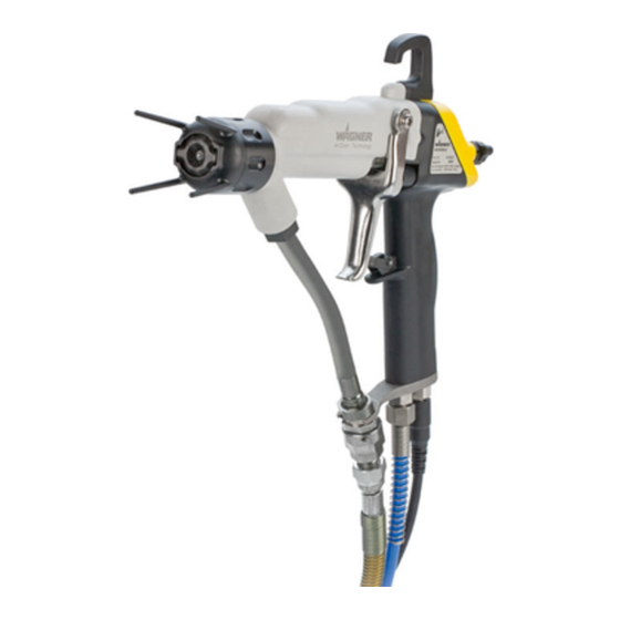
- Page 1 Translation of the original Operating manual GM 5000EAC Edition 03/2012 Electrostatic AirCoat Spray gun for manual operation with fl at or round jet nozzles II 2 G EEx 0.24 mJ 0102 B_03154 (in submission)
- Page 1 Translation of the original Operating manual GM 5000EAC Edition 03/2012 Electrostatic AirCoat Spray gun for manual operation with fl at or round jet nozzles II 2 G EEx 0.24 mJ 0102 B_03154 (in submission)
-
Page 3: Table Of Contents
Safety instructions for the operator 2.1.1 Electrical equipment 2.1.2 Personnel qualifi cations 2.1.3 A safe work environment Safety instructions for staff 2.2.1 Safe handling of WAGNER spray units 2.2.2 Earth the unit 2.2.3 Material hoses 2.2.4 Cleaning 2.2.5 Handling hazardous liquids, varnishes and paints 2.2.6... -
Page 3: Table Of Contents
Safety instructions for the operator 2.1.1 Electrical equipment 2.1.2 Personnel qualifi cations 2.1.3 A safe work environment Safety instructions for staff 2.2.1 Safe handling of WAGNER spray units 2.2.2 Earth the unit 2.2.3 Material hoses 2.2.4 Cleaning 2.2.5 Handling hazardous liquids, varnishes and paints 2.2.6... - Page 4 5000EAC. EDITION 03/2012 PART NUMBER DOC 2319150 OPERATING MANUAL Contents Preparation of paints 5.2.1 Viscosity conversion table Start-up 5.3.1 General rules for making adjustments to the spray gun 5.3.2 Preparation for starting up Working 5.4.1 Filling with working material 5.4.2 Start-up for spraying AirCoat 5.4.3 Cleaning of clogged round jet nozzles...
- Page 4 5000EAC. EDITION 03/2012 PART NUMBER DOC 2319150 OPERATING MANUAL Contents Preparation of paints 5.2.1 Viscosity conversion table Start-up 5.3.1 General rules for making adjustments to the spray gun 5.3.2 Preparation for starting up Working 5.4.1 Filling with working material 5.4.2 Start-up for spraying AirCoat 5.4.3 Cleaning of clogged round jet nozzles...
- Page 5 10.1 How to order spare parts? 10.2 GM 5000EAC spare parts list 10.2.1 GM 5000EAC spare parts list- End piece 10.2.2 GM 5000EAC spare parts list - Handle 10.3 Accessories spare parts lists 10.3.1 Flat jet nozzles spare parts list...
- Page 5 10.1 How to order spare parts? 10.2 GM 5000EAC spare parts list 10.2.1 GM 5000EAC spare parts list- End piece 10.2.2 GM 5000EAC spare parts list - Handle 10.3 Accessories spare parts lists 10.3.1 Flat jet nozzles spare parts list...
-
Page 6: About These Instructions
5000EAC. EDITION 03/2012 PART NUMBER DOC 2319150 OPERATING MANUAL ABOUT THESE INSTRUCTIONS LANGUAGES 2310481 2319150 2320152 2320153 2320154 WARNINGS, NOTES AND SYMBOLS IN THESE INSTRUCTIONS Warning instructions in this manual point out particular dangers to users and equipment and state measures for avoiding the hazard. These warning instructions fall into the following categories: Danger - imminent danger. -
Page 7: General Safety Instructions
5000EAC. EDITION 03/2012 PART NUMBER DOC 2319150 OPERATING MANUAL GENERAL SAFETY INSTRUCTIONS SAFETY INSTRUCTIONS FOR THE OPERATOR Keep these operating instructions to hand near the unit at all times. Always follow local regulations concerning occupational safety and accident prevention. 2.1.1 ELECTRICAL EQUIPMENT Electrical plant and unit To be provided in accordance with the local safety requirements with regard to the... -
Page 8: Safe Handling Of Wagner Spray Units
EDITION 03/2012 PART NUMBER DOC 2319150 OPERATING MANUAL 2.2.1 SAFE HANDLING OF WAGNER SPRAY UNITS The spray jet is under pressure and can cause dangerous injuries. Avoid injection of paint or cleaning agents: Never point the spray gun at people. -
Page 8: Safe Handling Of Wagner Spray Units
EDITION 03/2012 PART NUMBER DOC 2319150 OPERATING MANUAL 2.2.1 SAFE HANDLING OF WAGNER SPRAY UNITS The spray jet is under pressure and can cause dangerous injuries. Avoid injection of paint or cleaning agents: Never point the spray gun at people. -
Page 9: Cleaning
5000EAC. EDITION 03/2012 PART NUMBER DOC 2319150 OPERATING MANUAL 2.2.4 CLEANING De-energize the unit electrically. Disconnect the pneumatic supply line. Relieve the pressure from the unit. Ensure that the flash point of the cleaning agent is at least 15K above the ambient tem- perature. -
Page 10: Touching Hot Surfaces
5000EAC. EDITION 03/2012 PART NUMBER DOC 2319150 OPERATING MANUAL 2.2.6 TOUCHING HOT SURFACES ➞ Touch hot surfaces only if you are wearing protective gloves. ➞ When operating the unit with a coating material with a temperature of > 43 °C; 109.4 °F: - Identify the unit with a warning label that says „Warning - hot surface“. -
Page 11: Safety-Relevant Information About Discharges
2.5.1 CORRECT USE The electrostatic hand spray gun GM 5000EAC is suitable for spraying liquid materials, particularly coating materials, using the AirCoat method. Coating materials containing solvents of Explosion Class II A may be used. The spray gun may only be used in combination with the control unit VM 500 and VM 5000. -
Page 12: Explosion Protection Identifi Cation Fm
5000EAC. EDITION 03/2012 PART NUMBER DOC 2319150 OPERATING MANUAL Cleaning If there are deposits on the surfaces, the unit may form electrostatic charges. Flames or sparks can form if there is a discharge. Remove deposits from the surfaces to maintain conductivity. Use only a damp cloth to clean the unit. -
Page 13: Guarantee And Conformity Declarations
fitted , operated and maintained. If other makes of accessory and spare parts are used, the manufacturer‘s liability could be fully or partially null and void. The usage of original WAGNER accessories and spare parts guarantees that all safety regulations are observed. GUARANTEE CLAIM... -
Page 14: Ce-Conformity
II 2 G EEx 0.24mJ 0102 SIRA 11 ATEX 5374X CE Certificate of Conformity The certificate is enclosed with this product. The certificate of conformity can be reordered from your WAGNER representative, quoting the product and serial number. Part number : 2310487... -
Page 14: Ce-Conformity
II 2 G EEx 0.24mJ 0102 SIRA 11 ATEX 5374X CE Certificate of Conformity The certificate is enclosed with this product. The certificate of conformity can be reordered from your WAGNER representative, quoting the product and serial number. Part number : 2310487... -
Page 15: Description
The electrostatic spray gun can only be used with the VM 5000 or VM 500 control units. 4.1.1 PROCESSABLE MATERIALS ➞ With the GM 5000EAC gun, paints can be applied which contain solvent of explosion class II A. ➞ The spray gun basic version is suitable for processing of sprayed substances with an electrical resistance of >... -
Page 16: Scope Of Delivery
PART NUMBER DOC 2319150 OPERATING MANUAL SCOPE OF DELIVERY Quantity Part No. Description 2309871 GM 5000EAC spray gun Without control unit, material and air hose, electrical cable, air cap and nozzle. Each gun includes as standard equipment: Part No. Description 2309368... -
Page 17: Technical Data
73 dB(A) * 0.3 MPa; 3 bar; 43.5 psi material pressure * A rated sound pressure level measured at 1 m distance according to DIN EN 14462: 2005. Measurements GM 5000EAC F with fl at jet nozzle inches 11.02 1.81 10.39... -
Page 17: Technical Data
73 dB(A) * 0.3 MPa; 3 bar; 43.5 psi material pressure * A rated sound pressure level measured at 1 m distance according to DIN EN 14462: 2005. Measurements GM 5000EAC F with fl at jet nozzle inches 11.02 1.81 10.39... -
Page 18: Functional Description
5000EAC. EDITION 03/2012 PART NUMBER DOC 2319150 OPERATING MANUAL FUNCTIONAL DESCRIPTION 4.4.1 DESIGN OF SPRAY GUN (STANDARD VARIANT) Note: The nozzle parts (item 6; 7; 13 and 14) do not belong to the basic equipment of the spray gun. The different versions can be found in Chapter 9 „Accessories“. B_03156 Item Description... -
Page 19: Functions Of The Spray Gun
5000EAC. EDITION 03/2012 PART NUMBER DOC 2319150 OPERATING MANUAL 4.4.2 FUNCTIONS OF THE SPRAY GUN When the spray gun is connected to the control unit and the control unit is switched on, the pre-defi ned recipe (R1, R2 or R3) is shown on the gun display (2) as follows. -
Page 20: Spraying Process
5000EAC. EDITION 03/2012 PART NUMBER DOC 2319150 OPERATING MANUAL SPRAYING PROCESS 4.5.1 AIRCOAT ROUND JET SPRAY PROCESS In the AirCoat process, high pressure of 3-15 MPa; 30-150 bar; 435-2176 psi is used to atomize the material. The air at 0-0.25 MPa; 0-2.5 bar; 0-36 psi produces a soft jet. The size of the spray jet can be adjusted by turning the nozzle nut. -
Page 21: Electrical Resistance
5000EAC. EDITION 03/2012 PART NUMBER DOC 2319150 OPERATING MANUAL 4.5.3 ELECTRICAL RESISTANCE The spray gun produces an electrostatic fi eld by means of the high-voltage electrode. As a result, the particles of paint, which have been atomized by the spray gun, are carried to the earthed object by kinetic and electrostatic energy where they adhere, fi... -
Page 22: Start-Up And Operation
5000EAC. EDITION 03/2012 PART NUMBER DOC 2319150 OPERATING MANUAL START-UP AND OPERATION INSTALLATION AND CONNECTION 5.1.1 TYPICAL ELECTROSTATIC SPRAYING SYSTEM B_03158 Item Designation GM 5000EACF spray gun Gun cable Item Designation Grounding cable Item Designation Compressed air Material hose Pneumatic pumps connection Carriage Return valve... -
Page 23: Ventilation Of The Spray Booth
PART NUMBER DOC 2319150 OPERATING MANUAL The GM 5000EAC spray gun must be used a part of an electrostatic spraying system (Spraypack). The spraying system shown in the fi gure B_03158 is only one example of an electrostatic spraying system. Contact your Wagner distributor for assistance in designing a system to meet your needs. -
Page 24: Paint Supplies
5000EAC. EDITION 03/2012 PART NUMBER DOC 2319150 OPERATING MANUAL 5.1.4 PAINT SUPPLIES CAUTION Impurities in the spraying system! Spray gun blockage, materials harden in the spraying system Flush the spray gun and paint supply with a suitable cleaning agent. SIHI_0001_GB DANGER Bursting hose, bursting threaded joints! Danger to life from injection of material... -
Page 25: Earthing
5000EAC. EDITION 03/2012 PART NUMBER DOC 2319150 OPERATING MANUAL 5.1.5 EARTHING Perfect earthing of all conductive parts such as fl oors, walls, roofs, is important for optimum coating and safety. Barriers, work pieces, transport devices, coating material container, automatic movement system or construction parts in the spray area must be connected to the earthing system, with exception of the high-voltage parts during normal operation. -
Page 25: Earthing
5000EAC. EDITION 03/2012 PART NUMBER DOC 2319150 OPERATING MANUAL 5.1.5 EARTHING Perfect earthing of all conductive parts such as fl oors, walls, roofs, is important for optimum coating and safety. Barriers, work pieces, transport devices, coating material container, automatic movement system or construction parts in the spray area must be connected to the earthing system, with exception of the high-voltage parts during normal operation. - Page 26 5000EAC. EDITION 03/2012 PART NUMBER DOC 2319150 OPERATING MANUAL Earthing schema (example) Conveyor Note for the sprayer The work shoes and if Control unit used the gloves must be derivable. Work piece Earthing cable Pump R max < 1 MΩ Paint container Spraying stand B_03234...
- Page 26 5000EAC. EDITION 03/2012 PART NUMBER DOC 2319150 OPERATING MANUAL Earthing schema (example) Conveyor Note for the sprayer The work shoes and if Control unit used the gloves must be derivable. Work piece Earthing cable Pump R max < 1 MΩ Paint container Spraying stand B_03234...
-
Page 27: Preparation Of Paints
0.16 inches). Processing of up to 60 DIN-s is generally possible without problem, if high coating thicknesses are required. The Wagner AirCoat fl at jet spraying process determined optimally the different viscosity of the paint by two air cap types. These can be found in the Accessories. -
Page 28: Start-Up
5000EAC. EDITION 03/2012 PART NUMBER DOC 2319150 OPERATING MANUAL START-UP 5.3.1 GENERAL RULES FOR MAKING ADJUSTMENTS TO THE SPRAY GUN ➞ Observe safety instructions in Chapter 2. DANGER High voltage field! Danger to life from malfunctioning heart pacemakers Ensure that persons with heart pacemakers: Do not work with the electrostatic spray gun. -
Page 28: Start-Up
5000EAC. EDITION 03/2012 PART NUMBER DOC 2319150 OPERATING MANUAL START-UP 5.3.1 GENERAL RULES FOR MAKING ADJUSTMENTS TO THE SPRAY GUN ➞ Observe safety instructions in Chapter 2. DANGER High voltage field! Danger to life from malfunctioning heart pacemakers Ensure that persons with heart pacemakers: Do not work with the electrostatic spray gun. - Page 29 PART NUMBER DOC 2319150 OPERATING MANUAL ➞ Check the level of the release agent in the Wagner pneumatic pump and if necessary fi ll the release agent up. ➞ Provide material container, containers for detergent and an empty container for return.
- Page 29 PART NUMBER DOC 2319150 OPERATING MANUAL ➞ Check the level of the release agent in the Wagner pneumatic pump and if necessary fi ll the release agent up. ➞ Provide material container, containers for detergent and an empty container for return.
-
Page 30: Working
5000EAC. EDITION 03/2012 PART NUMBER DOC 2319150 OPERATING MANUAL B_03158 WORKING 5.4.1 FILLING WITH WORKING MATERIAL 1. Provide an empty container for return (18). See image B_03158. 2. Place suction hose (7) in the container with working material (19). Note: If the pump is equipped with a rigid suction system, it should only be diped in into the working material in maximum to the middle of the inlet housing! 3. -
Page 31: Start-Up For Spraying Aircoat
5000EAC. EDITION 03/2012 PART NUMBER DOC 2319150 OPERATING MANUAL 8. Close return valve (17). 9. Point the gun, without nozzle, into container (18) and open it. 10. Slowly open the ball valve (11). 11. Close ball valve (11) as soon as pure working material without any air inclusions starts coming from the gun. -
Page 32: Cleaning Of Clogged Round Jet Nozzles
5000EAC. EDITION 03/2012 PART NUMBER DOC 2319150 OPERATING MANUAL 5.4.3 CLEANING OF CLOGGED ROUND JET NOZZLES DANGER Exploding gas/ air mixture! Danger to life from flying parts and burns Never spray into a closed container. Earth the container. SIHI_0008_GB 1. By means of nozzle spanner (2), loosen nozzle insert (1) by a half turn. -
Page 33: Changing From Aircoat Round Jet To Aircoat Fl At Jet
5000EAC. EDITION 03/2012 PART NUMBER DOC 2319150 OPERATING MANUAL 5.4.5 CHANGING FROM AIRCOAT ROUND JET TO AIRCOAT FLAT JET 1. Flush the spray gun (1) out thoroughly with cleaning agent. 2. Relieve the pressure of gun and unit. 3. Save the spray gun (1) using the trigger lock. 4. -
Page 34: Replacing Aircoat Fl At Jet Nozzles
5000EAC. EDITION 03/2012 PART NUMBER DOC 2319150 OPERATING MANUAL 5.4.6 REPLACING AIRCOAT FLAT JET NOZZLES 1. Switch off control unit. 2. Relieve the pressure of gun (1) and unit! 3. Save the spray gun (1) using the trigger lock. 4. Unscrew union nut (12) and remove air cap (10). 5. -
Page 34: Replacing Aircoat Fl At Jet Nozzles
5000EAC. EDITION 03/2012 PART NUMBER DOC 2319150 OPERATING MANUAL 5.4.6 REPLACING AIRCOAT FLAT JET NOZZLES 1. Switch off control unit. 2. Relieve the pressure of gun (1) and unit! 3. Save the spray gun (1) using the trigger lock. 4. Unscrew union nut (12) and remove air cap (10). 5. - Page 35 5000EAC. EDITION 03/2012 PART NUMBER DOC 2319150 OPERATING MANUAL 6. Insert air cap (10) with integrated ACF 5000 nozzle (11) into the union nut (9). Make sure that the air cap horns (Y) lie in the recess of the nozzle guard. 7.
- Page 35 5000EAC. EDITION 03/2012 PART NUMBER DOC 2319150 OPERATING MANUAL 6. Insert air cap (10) with integrated ACF 5000 nozzle (11) into the union nut (9). Make sure that the air cap horns (Y) lie in the recess of the nozzle guard. 7.
-
Page 36: Maintenance
Risk of injury and damage to the equipment Repairs and part replacement may only be carried out by specially trained staff or a WAGNER service center. Before all work on the unit and in the event of work interruptions: - Switch off the energy/compressed air supply. -
Page 36: Maintenance
Risk of injury and damage to the equipment Repairs and part replacement may only be carried out by specially trained staff or a WAGNER service center. Before all work on the unit and in the event of work interruptions: - Switch off the energy/compressed air supply. - Page 37 5000EAC. EDITION 03/2012 PART NUMBER DOC 2319150 OPERATING MANUAL DANGER Exploding gas/ air mixture! Danger to life from flying parts and burns Never spray into a closed container. Earth the container. SIHI_0008_GB 1. Switch off control unit. 2. Ensure that the material pressure is relieved and shut off the air supply to the gun. 3.
- Page 37 5000EAC. EDITION 03/2012 PART NUMBER DOC 2319150 OPERATING MANUAL DANGER Exploding gas/ air mixture! Danger to life from flying parts and burns Never spray into a closed container. Earth the container. SIHI_0008_GB 1. Switch off control unit. 2. Ensure that the material pressure is relieved and shut off the air supply to the gun. 3.
-
Page 38: Dismantling Of The Spray Gun
5000EAC. EDITION 03/2012 PART NUMBER DOC 2319150 OPERATING MANUAL DISMANTLING OF THE SPRAY GUN SW12 SW12 B_03194 Torx 25 SW19 B_03195 SW21... -
Page 38: Dismantling Of The Spray Gun
5000EAC. EDITION 03/2012 PART NUMBER DOC 2319150 OPERATING MANUAL DISMANTLING OF THE SPRAY GUN SW12 SW12 B_03194 Torx 25 SW19 B_03195 SW21... - Page 39 5000EAC. EDITION 03/2012 PART NUMBER DOC 2319150 OPERATING MANUAL Carefully release the cascade without pliers. SW19 B_03196 SW22 SW19 Assembly tool for Note: needle valve. Loosen AC valve tip by hand Part no. 2309368 using an assembly tool. Use assembly tool, socket or ring spanner (no wrench).
- Page 39 5000EAC. EDITION 03/2012 PART NUMBER DOC 2319150 OPERATING MANUAL Carefully release the cascade without pliers. SW19 B_03196 SW22 SW19 Assembly tool for Note: needle valve. Loosen AC valve tip by hand Part no. 2309368 using an assembly tool. Use assembly tool, socket or ring spanner (no wrench).
- Page 40 5000EAC. EDITION 03/2012 PART NUMBER DOC 2319150 OPERATING MANUAL 1. Remove pressure spring (4). 2. Loosen clamping screw (1) completely with assembly tool (5). 3. Unscrew the complete package (3) via the complete valve rod unit (2, 6 and 7) or pull out the valve rod unit and unscrew it using an Allen key SW5.
- Page 40 5000EAC. EDITION 03/2012 PART NUMBER DOC 2319150 OPERATING MANUAL 1. Remove pressure spring (4). 2. Loosen clamping screw (1) completely with assembly tool (5). 3. Unscrew the complete package (3) via the complete valve rod unit (2, 6 and 7) or pull out the valve rod unit and unscrew it using an Allen key SW5.
-
Page 41: Cleaning The Parts After Disassembly
5000EAC. EDITION 03/2012 PART NUMBER DOC 2319150 OPERATING MANUAL CLEANING THE PARTS AFTER DISASSEMBLY ATTENTION Please note: ➞ All reusable parts (except for the parts that conduct the high-voltage such as cascade, end piece, plug compl. etc.) should be cleaned thoroughly using a suitable cleaning agent. -
Page 42: Assembling The Spray Gun
5000EAC. EDITION 03/2012 PART NUMBER DOC 2319150 OPERATING MANUAL ASSEMBLING THE SPRAY GUN SW9 1 Nm B_03448 Ensure the correct insertion position! Mounting materials: Item Part No. Description 9992590 Loctite 222 B_03201 9992698 Vaseline white PHHV II 9992831 Loctite 542 SW14 3 Nm 9992511 Loctite 243... -
Page 42: Assembling The Spray Gun
5000EAC. EDITION 03/2012 PART NUMBER DOC 2319150 OPERATING MANUAL ASSEMBLING THE SPRAY GUN SW9 1 Nm B_03448 Ensure the correct insertion position! Mounting materials: Item Part No. Description 9992590 Loctite 222 B_03201 9992698 Vaseline white PHHV II 9992831 Loctite 542 SW14 3 Nm 9992511 Loctite 243... - Page 43 5000EAC. EDITION 03/2012 PART NUMBER DOC 2319150 OPERATING MANUAL Insertion position compl. package Set measure X with withdrawal nut and then fasten it with the threaded pin (SW2). X = 123 ±0.1 Push together the valve rod unit and the compl.
- Page 43 5000EAC. EDITION 03/2012 PART NUMBER DOC 2319150 OPERATING MANUAL Insertion position compl. package Set measure X with withdrawal nut and then fasten it with the threaded pin (SW2). X = 123 ±0.1 Push together the valve rod unit and the compl.
- Page 44 5000EAC. EDITION 03/2012 PART NUMBER DOC 2319150 OPERATING MANUAL Clean and degrease the inside of the end piece and the cascade, then grease the cascade surface with Vaseline. SW19 0.8 Nm 2.5 Nm SW19 B_03205 SW21 B_03204 SW22 SW19 Push the trigger upward into the air valve piston.
- Page 44 5000EAC. EDITION 03/2012 PART NUMBER DOC 2319150 OPERATING MANUAL Clean and degrease the inside of the end piece and the cascade, then grease the cascade surface with Vaseline. SW19 0.8 Nm 2.5 Nm SW19 B_03205 SW21 B_03204 SW22 SW19 Push the trigger upward into the air valve piston.
- Page 45 5000EAC. EDITION 03/2012 PART NUMBER DOC 2319150 OPERATING MANUAL 0.8 Nm Ensure the correct insertion position! SW12 SW12 B_03207 Flat jet nozzle Assembly see chapter 10.3.1. Diverse nozzle sizes see chapter 9.2. Round jet nozzle Assembly see chapter 10.3.2. Diverse nozzle sizes see chapter 9.1. B_03208...
- Page 45 5000EAC. EDITION 03/2012 PART NUMBER DOC 2319150 OPERATING MANUAL 0.8 Nm Ensure the correct insertion position! SW12 SW12 B_03207 Flat jet nozzle Assembly see chapter 10.3.1. Diverse nozzle sizes see chapter 9.2. Round jet nozzle Assembly see chapter 10.3.2. Diverse nozzle sizes see chapter 9.1. B_03208...
-
Page 46: Function Test After Assembly Of The Gun
5000EAC. EDITION 03/2012 PART NUMBER DOC 2319150 OPERATING MANUAL FUNCTION TEST AFTER ASSEMBLY OF THE GUN 6.6.1 CHECKING THE HIGH-VOLTAGE Necessary test equipment: VM 500 or VM 5000 control unit and HV200 high-voltage tester. High-voltage measurements on spraying gun. Connect gun cable to control unit. Take the spray gun in your hand and hold into open space. Switch on control unit and actuate trigger guard. -
Page 47: Air Tests
5000EAC. EDITION 03/2012 PART NUMBER DOC 2319150 OPERATING MANUAL 6.6.2 AIR TESTS Connect test or air hose to the spray gun and switch on mains pressure 0.8 MPa; 8 bar; 116 psi max. Checking the air valve The air valve must switch on and off cleanly. Test up to approx. -
Page 47: Air Tests
5000EAC. EDITION 03/2012 PART NUMBER DOC 2319150 OPERATING MANUAL 6.6.2 AIR TESTS Connect test or air hose to the spray gun and switch on mains pressure 0.8 MPa; 8 bar; 116 psi max. Checking the air valve The air valve must switch on and off cleanly. Test up to approx. -
Page 48: Check Spray Pattern
5000EAC. EDITION 03/2012 PART NUMBER DOC 2319150 OPERATING MANUAL 6.6.4 CHECK SPRAY PATTERN Start AirCoat spraying (without electrostatics) 1. Start up with material supply set to approx. 8 MPa; 80 bar; 1160 psi operating pressure. 2. Spray (release trigger safety catch and pull trigger) and check the atomisation. 3. -
Page 49: Trouble Shooting And Solution
5000EAC. EDITION 03/2012 PART NUMBER DOC 2319150 OPERATING MANUAL TROUBLE SHOOTING AND SOLUTION Functional fault Cause Remedy Insuffi cient material output • Nozzle too small. • Select larger nozzle (see Accessories chapter 9). • Material pressure too • Increase material pressure. low. -
Page 50: Product Disposal
Your waste Wagner electrical device will be taken back by us or our representatives and disposed of environmentally correctly. Please contact one of our service points or one of our representatives or us directly to this purpose. -
Page 50: Product Disposal
Your waste Wagner electrical device will be taken back by us or our representatives and disposed of environmentally correctly. Please contact one of our service points or one of our representatives or us directly to this purpose. -
Page 51: Accessories
5000EAC. EDITION 03/2012 PART NUMBER DOC 2319150 OPERATING MANUAL ACCESSORIES ACR 5000 ROUND JET NOZZLE CAP Part No. Description 2309883 ACR 5000 round jet nozzle cap (with nozzle spanner, without AC round jet nozzle insert) B_03210 9.1.1 AIRCOAT ROUND JET NOZZLE INSERTS The round jet nozzles are especially suited to spray pipes, profi... -
Page 52: Acf 5000 Aircoat Fl At Jet Nozzles
5000EAC. EDITION 03/2012 PART NUMBER DOC 2319150 OPERATING MANUAL 9.2.2 ACF 5000 AIRCOAT FLAT JET NOZZLES Application B_03163 395107 07/10 0.18; 0.007 10° Natural paint 395207 07/20 20° 395407 07/40 40° 395109 09/10 0.23; 0.009 10° Transparent lacquer 395209 09/20 20°... -
Page 52: Acf 5000 Aircoat Fl At Jet Nozzles
5000EAC. EDITION 03/2012 PART NUMBER DOC 2319150 OPERATING MANUAL 9.2.2 ACF 5000 AIRCOAT FLAT JET NOZZLES Application B_03163 395107 07/10 0.18; 0.007 10° Natural paint 395207 07/20 20° 395407 07/40 40° 395109 09/10 0.23; 0.009 10° Transparent lacquer 395209 09/20 20°... - Page 53 5000EAC. EDITION 03/2012 PART NUMBER DOC 2319150 OPERATING MANUAL Application B_03163 395219 19/20 0.48; 0.019 20° Rust proofing paint 395319 19/30 30° Latex paint 395419 19/40 40° 395519 19/50 50° 395619 19/60 60° 395819 19/80 80° 395221 21/20 0.53; 0.021 20°...
- Page 53 5000EAC. EDITION 03/2012 PART NUMBER DOC 2319150 OPERATING MANUAL Application B_03163 395219 19/20 0.48; 0.019 20° Rust proofing paint 395319 19/30 30° Latex paint 395419 19/40 40° 395519 19/50 50° 395619 19/60 60° 395819 19/80 80° 395221 21/20 0.53; 0.021 20°...
-
Page 54: Filters
Edge fi lter 200 mesh (yellow) REDUCTION FITTINGS FOR HIGH-PRESSURE HOSES The classifi cation of WAGNER fi ttings is consistent with the following classifi cation, each separated by high-pressure and low pressure fi ttings. Double fi tting - Male / Male thread Reduction fi... -
Page 54: Filters
Edge fi lter 200 mesh (yellow) REDUCTION FITTINGS FOR HIGH-PRESSURE HOSES The classifi cation of WAGNER fi ttings is consistent with the following classifi cation, each separated by high-pressure and low pressure fi ttings. Double fi tting - Male / Male thread Reduction fi... -
Page 55: Hoses And Electrical Cables
HOSES AND ELECTRICAL CABLES 9.5.1 STANDARD HOSE SETS AND COMPONENTS B_03217 Item Part No. Description 2309857 GM 5000EAC hose set (7.5 m) Consisting of: 9984573 High pressure hose-DN4-PN270-¼“NPS-7.5 m-PA 2312060 Air hose compl. (8.0 m) 2307293 GM 5000E gun cable (10.0 m) 3676437 Protective hose mesh PP30 (7.0 m) -
Page 56: Hose Sets For Low Impedance Materials
- inlet diameter 4 mm - inside hose material FEP B_03216 Item Part No. Description 2309951 GM 5000EAC hose set (7.5 m), Low R Consisting of: 2310468 EAC high pressure paint hose, compl. (7.5 m) LowR 2312060 Air hose compl. (8.0 m) 2307293 GM 5000E gun cable (10.0 m) -
Page 57: Gun Cable And Gun Cable Extensions
5000EAC. EDITION 03/2012 PART NUMBER DOC 2319150 OPERATING MANUAL 9.5.3 GUN CABLE AND GUN CABLE EXTENSIONS Part No. Description 2307295 GM 5000E extension cable 10 m B_03219 2307296 GM 5000E extension cable 20 m MISCELLANEOUS Part No. Description 2319653 Gun protective cover B_03693 259010 HV200 N high-voltage tester... -
Page 57: Gun Cable And Gun Cable Extensions
5000EAC. EDITION 03/2012 PART NUMBER DOC 2319150 OPERATING MANUAL 9.5.3 GUN CABLE AND GUN CABLE EXTENSIONS Part No. Description 2307295 GM 5000E extension cable 10 m B_03219 2307296 GM 5000E extension cable 20 m MISCELLANEOUS Part No. Description 2319653 Gun protective cover B_03693 259010 HV200 N high-voltage tester... - Page 58 2309368 Assembly tool valve needle B_03451 128901 ACR nozzle spanner 2325263 Assembly tool clamping screw B_03681 2326485 GM 5000E wall mount (left/right) B_03699 2324766 Swivel for air B_03720 2327060 Fitting-SJM-GM5000EAC-1/4“NPS (swivel material) B_03719 2327061 GM 5000EAC swivel set B_03720 B_03719...
- Page 58 2309368 Assembly tool valve needle B_03451 128901 ACR nozzle spanner 2325263 Assembly tool clamping screw B_03681 2326485 GM 5000E wall mount (left/right) B_03699 2324766 Swivel for air B_03720 2327060 Fitting-SJM-GM5000EAC-1/4“NPS (swivel material) B_03719 2327061 GM 5000EAC swivel set B_03720 B_03719...
-
Page 59: Spare Parts
Risk of injury and damage to the equipment Repairs and part replacement may only be carried out by specially trained staff or a WAGNER service center. Before all work on the unit and in the event of work interruptions: - Switch off the energy/compressed air supply. -
Page 59: Spare Parts
Risk of injury and damage to the equipment Repairs and part replacement may only be carried out by specially trained staff or a WAGNER service center. Before all work on the unit and in the event of work interruptions: - Switch off the energy/compressed air supply. -
Page 60: Gm 5000Eac Spare Parts List
5000EAC. EDITION 03/2012 PART NUMBER DOC 2319150 OPERATING MANUAL 10.2 GM 5000EAC SPARE PARTS LIST B_03153... -
Page 60: Gm 5000Eac Spare Parts List
5000EAC. EDITION 03/2012 PART NUMBER DOC 2319150 OPERATING MANUAL 10.2 GM 5000EAC SPARE PARTS LIST B_03153... - Page 61 5000EAC. EDITION 03/2012 PART NUMBER DOC 2319150 OPERATING MANUAL GM 5000EAC spare parts list Item K Quantity Part No. Description 2309871 GM 5000EAC standard variant ★ ◆ 2314283 AC contacting ◆ ★ 9952777 High resistance, bare 9960808 Socket contact component GM 5000EAC end piece compl.
- Page 61 5000EAC. EDITION 03/2012 PART NUMBER DOC 2319150 OPERATING MANUAL GM 5000EAC spare parts list Item K Quantity Part No. Description 2309871 GM 5000EAC standard variant ★ ◆ 2314283 AC contacting ◆ ★ 9952777 High resistance, bare 9960808 Socket contact component GM 5000EAC end piece compl.
-
Page 62: Gm 5000Eac Spare Parts List- End Piece
5000EAC. EDITION 03/2012 PART NUMBER DOC 2319150 OPERATING MANUAL 10.2.1 GM 5000EAC SPARE PARTS LIST- END PIECE B_03164 Ensure the correct insertion position! X = 123 ±0.1... -
Page 62: Gm 5000Eac Spare Parts List- End Piece
5000EAC. EDITION 03/2012 PART NUMBER DOC 2319150 OPERATING MANUAL 10.2.1 GM 5000EAC SPARE PARTS LIST- END PIECE B_03164 Ensure the correct insertion position! X = 123 ±0.1... - Page 63 5000EAC. EDITION 03/2012 PART NUMBER DOC 2319150 OPERATING MANUAL GM 5000EAC end piece spare parts list Item Quantity Part No. Description GM 5000EAC end piece compl. ★ 2313314 AC air manifold ring ◆ ★ 2307180 O-ring, sheathed ◆ ★ 2312175 AC valve housing compl.
- Page 63 5000EAC. EDITION 03/2012 PART NUMBER DOC 2319150 OPERATING MANUAL GM 5000EAC end piece spare parts list Item Quantity Part No. Description GM 5000EAC end piece compl. ★ 2313314 AC air manifold ring ◆ ★ 2307180 O-ring, sheathed ◆ ★ 2312175 AC valve housing compl.
-
Page 64: Gm 5000Eac Spare Parts List - Handle
5000EAC. EDITION 03/2012 PART NUMBER DOC 2319150 OPERATING MANUAL 10.2.2 GM 5000EAC SPARE PARTS LIST - HANDLE 18 19 B_03165... -
Page 64: Gm 5000Eac Spare Parts List - Handle
5000EAC. EDITION 03/2012 PART NUMBER DOC 2319150 OPERATING MANUAL 10.2.2 GM 5000EAC SPARE PARTS LIST - HANDLE 18 19 B_03165... - Page 65 5000EAC. EDITION 03/2012 PART NUMBER DOC 2319150 OPERATING MANUAL GM 5000EAC handle spare parts list Item K Quantity Part No. Description GM 5000EAC handle compl. 2307288 Nipple ◆ ★ 9971025 O-ring 2315344 Hose holder 2312182 Plug compl. 2314270 Handle compl.
- Page 65 5000EAC. EDITION 03/2012 PART NUMBER DOC 2319150 OPERATING MANUAL GM 5000EAC handle spare parts list Item K Quantity Part No. Description GM 5000EAC handle compl. 2307288 Nipple ◆ ★ 9971025 O-ring 2315344 Hose holder 2312182 Plug compl. 2314270 Handle compl.
-
Page 66: Accessories Spare Parts Lists
5000EAC. EDITION 03/2012 PART NUMBER DOC 2319150 OPERATING MANUAL 10.3 ACCESSORIES SPARE PARTS LISTS 10.3.1 FLAT JET NOZZLES SPARE PARTS LIST B_03168 Flat jet nozzles spare parts list Item Quantity Part No. Description 2315775 AC union nut compl. 2309882 LV air cap compl. 2314203 HV air cap compl. -
Page 67: Acr 5000 Round Jet Nozzle Cap Spare Parts List
5000EAC. EDITION 03/2012 PART NUMBER DOC 2319150 OPERATING MANUAL 10.3.2 ACR 5000 ROUND JET NOZZLE CAP SPARE PARTS LIST B_03169 ACR 5000 round jet nozzle cap spare parts list Item Quantity Part No. Description 2309883 ACR 5000 round jet nozzle cap 2307220 Nozzle nut ◆... -
Page 67: Acr 5000 Round Jet Nozzle Cap Spare Parts List
5000EAC. EDITION 03/2012 PART NUMBER DOC 2319150 OPERATING MANUAL 10.3.2 ACR 5000 ROUND JET NOZZLE CAP SPARE PARTS LIST B_03169 ACR 5000 round jet nozzle cap spare parts list Item Quantity Part No. Description 2309883 ACR 5000 round jet nozzle cap 2307220 Nozzle nut ◆... - Page 68 5000EAC. EDITION 03/2012 PART NUMBER DOC 2319150 OPERATING MANUAL...
- Page 68 5000EAC. EDITION 03/2012 PART NUMBER DOC 2319150 OPERATING MANUAL...
- Page 69 5000EAC. EDITION 03/2012 PART NUMBER DOC 2319150 OPERATING MANUAL...
- Page 69 5000EAC. EDITION 03/2012 PART NUMBER DOC 2319150 OPERATING MANUAL...
- Page 70 DK- 8600 Silkeborg Telephone: +32 (0)2 269 4675 Telephone: +45 70 200 245 Telefax: +32 (0)2 269 7845 Telefax: +45 86 856 027 E-Mail: info@wsb-wagner.be / HP www.wsb-wagner.eu E-Mail info@wagner-industri.com United Kingdom France WAGNER Spraytech (UK) Ltd. J. WAGNER France S.A.R.L.
- Page 70 DK- 8600 Silkeborg Telephone: +32 (0)2 269 4675 Telephone: +45 70 200 245 Telefax: +32 (0)2 269 7845 Telefax: +45 86 856 027 E-Mail: info@wsb-wagner.be / HP www.wsb-wagner.eu E-Mail info@wagner-industri.com United Kingdom France WAGNER Spraytech (UK) Ltd. J. WAGNER France S.A.R.L.
- Page 72 2319150...
- Page 72 2319150...