Table of Contents
Advertisement
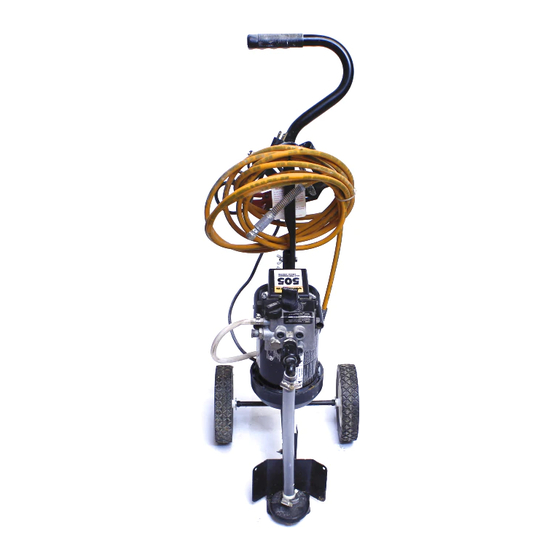
HIGH PERFORMANCE
AIRLESS SPRAYER
Read Warnings
Attach Paint Hose
Set Pressure
Maintenance
PRINTED IN THE U. S. A.
R
505
OWNER'S MANUAL
Easy Does It From Set Up to Clean Up
Assemble Cart
Prepare to Prime
Spray
Optional Hopper Accessory
Attach Tip to Gun
Attach Suction Set
Short Term Storage
Questions? ... Need Help?
Wagner maintains a toll-free help line for you should
you have any comments or problems with this Wagner
product. Call us first ....for answers fast...
Wagner Technical Service
1-800-328-8251
Hours: Weekdays: 8:00 - 4:30 Central Time
Weekends: 9:00 - 4:00 Central Time
1
Attach Return Hose
Prime Pump
Clean Up
OR
Form No. 0270993-11/93
Advertisement
Table of Contents
Troubleshooting

Related Manuals for WAGNER 505


Summary of Contents for WAGNER 505
- Page 1 HIGH PERFORMANCE AIRLESS SPRAYER Easy Does It From Set Up to Clean Up Read Warnings Attach Paint Hose Set Pressure Maintenance Optional Hopper Accessory PRINTED IN THE U. S. A. OWNER'S MANUAL Attach Tip to Gun Assemble Cart Attach Suction Set Prepare to Prime Spray Short Term Storage...
-
Page 2: Table Of Contents
Set Up ... 9-11 Priming ... 12-14 Spraying ... 15-18 Components: The shipping carton for your 505 Painting System contains the following components: Cart frame with wheels, motor and pump attached. Cart handle Pail bracket/cart foot Suction set and return tube... -
Page 3: Safety Precautions
SAFETY PRECAUTIONS This manual contains information which must be read and understood before using the equipment. When you come to an area which has one of the following symbols, pay particular attention and make certain to heed the safeguard. Important safety information indicates a hazard which may cause serious injury or loss of life. Important information that tells how to prevent damage to equipment or how to avoid causes of minor injuries. - Page 4 HAZARD Injection Injury - A high pressure stream of paint pro- duced by this equipment can pierce the skin and underlying tissues, leading to serious injury and pos- sible amputation. DO NOT TREAT AS A SIMPLE CUT! Injection- can lead to amputation. See a physician im- mediately.
- Page 5 HAZARD Explosion or fire - Solvent and paint fumes can explode or ignite, causing property damage and or severe injury. WARNING • Exhaust and fresh air introduction must be provided to keep the air within the spray area free from accumulation of flammable vapors.
-
Page 6: Safety Precautions
HAZARD Explosion hazard incompatible materials - May cause property damage or severe injury. Hazardous vapors - Paints, solvents, insecticides, and other materials may be harmful if inhaled causing se- vere nausea, fainting, or poisoning. General - May cause property damage or severe injury. WARNING •... -
Page 7: Extension Cord
Extension Cord Use only a 3-wire extension cord that has a 3-blade grounding plug and a 3-slot receptacle that will accept the plug on the product. Make sure your extension cord is in good condition. When using an extension cord, be sure to use one heavy enough to carry the current your product will draw. -
Page 8: Pressure Relief Procedure
Pressure Relief Procedure Follow this procedure after the unit is assembled and before any operation which involves the spray gun such as changing tips or accessories, or cleaning and maintenance. 1. Make sure PRESSURE CONTROL KNOB is at its lowest setting (counterclockwise). -
Page 9: Set Up
Tools needed: Some assembly is required to get your Wagner 505 Airless Sprayer ready to go. You will need two adjustable wrenches, a screw driver and a pair of pliers. NOTE: Sprayer should remain unplugged during assembly. 1. Slide pail bracket (1) onto cart frame and attach with one bolt, washer and wing nut (2). - Page 10 1. Lock gun. See Figure 4. Locked Unlocked Position Position Figure 4 - Gun in Locked & Unlocked Position 2. If spray tip is not pre- assembled, (See Figure 5) insert tip (1) into tip guard, (2) and turn 90° coun- terclockwise to spray position (arrow pointing away from gun).
- Page 11 ATTACH RETURN HOSE 1. Be sure motor switch is turned OFF. 2. Screw brass fitting of return tube into upper port on side of pump. (The brass fitting is located in the literature set.) Tighten firmly by hand. See figure above.
-
Page 12: Priming
1. Lay unit back on its handle so inlet valve is facing up. Fill inlet valve with water or light household oil. 2. Make sure Prime/Spray Knob is in Prime A position and Pressure Knob is turned to the lowest pressure. (Counter clockwise) See Figure 11. -
Page 13: Prime The Pump
ATTACH SUCTION SET 1. Attach Suction Tube to inlet valve and tighten firmly by hand. See Figure 15. Be sure threads are straight so the fitting turns freely without binding. (Do Not cross thread) Figure 15 - Attaching Suction Tube 2. - Page 14 Continued from page 13 3. TURN SPRAYER ON. 4. Turn PRESSURE CONTROL KNOB between half and full pressure. See Figure 20. You should then be able to see the paint move through the suction tube to the pump. Continue until paint flows through the return tube.
-
Page 15: Spraying
1. Be sure paint hose is free of kinks and clear of traffic or objects with sharp cutting edges. 2. Return PRESSURE CONTROL KNOB to its lowest setting (counterclockwise). Figure 21. Figure 21 - Pressure Control Knob Setting 3. Turn PRIMING KNOB to SPRAY PrimeA Spray B Knob... -
Page 16: Spraying Technique
1. The key to a good paint job is an even coating over the entire surface. With spray painting, this is done by using even strokes, with your arm moving at a con- stant speed and keeping the spray gun a constant distance from the surface. - Page 17 5. The spray gun should be triggered off at the end of each stroke and on again at the beginning of the next. This avoids paint buildup at the end of the stroke which may result in runs and sags. Triggering at the end of the stroke also saves paint and results in a better looking job.
- Page 18 Continued from page 17 Cleaning The Spray Gun Filter The spray gun includes a filter to catch particles before they reach the spray tip. If this filter becomes clogged or obstructed it will reduce the flow of paint, changing the spray pattern and possibly damaging the filter.
-
Page 19: Short Term Storage
SHORT-TERM/OVERNIGHT STORAGE Shut-down 1. Lock the gun and reduce the pressure. Turn the sprayer to prime A and shut it off. Unplug sprayer. Leave the suction set in the paint. Refer to Pressure Relief Procedure. 2. For latex materials only, pour 1/2 cup water slowly on the top of the paint to prevent the paint from drying. -
Page 20: Cleanup And Long Term Shutdown
Do not allow paint to build up on WARNING the motor. Overheating of the motor will result. Do not allow flammable solvents to come in contact with the motor, which could ignite. NOTE: You will need an extra bucket with cleaning solution, a toothbrush, an adjustable wrench and rags. - Page 21 14. Clean spray tip and gun filter with a soft brush. Reassemble spray tip in cleaning position. (Arrow points to back of the gun.) 15. Attach paint hose to gun,tighten with two wrenches. Figure 40 - Attach Paint Hose to Gun CLEAN UP 16.
- Page 22 21. Lock gun, reduce pressure and turn Prime/Spray Knob to prime A . 22. Lay unit back on handle so inlet valve is facing upward. Clean threads of inlet valve with a damp cloth. Fill inlet valve with light household oil. See Figure 43.
-
Page 23: Removing And Cleaning Inlet Valve
Follow these procedures when encounter- ing problems indicated in the trouble shoot- ing section. Removing and Cleaning Inlet Valve 1. Be sure sprayer is off. 2. Using a 27 millimeter socket or box end wrench, remove the inlet valve assembly. Remove Inlet Valve Figure 45- Removing Inlet Valve... -
Page 24: Maintenance
2. If possible, leave the copper washer under the cap in place. At least be sure to replace it with the same side up. (The top will show the imprint of the end cap, while the bottom should be perfectly flat to match seat in the pump casting.) See Paint Pump Assem- bly Parts Diagram,Item 4 for replacement part num- ber. -
Page 25: Optional Hopper
OPTIONAL HOPPER ASSEMBLY CONVERTING SPRAYER FOR HOPPER OPERATION The hopper assembly consists of the hopper, hopper return tube and hopper screen. To make the conversion: 1. Remove suction tube and return tube and brass return tube fitting from the unit. 2. -
Page 26: Trouble Shooting
Problem Sprayer does not start up. Sprayer starts up but does not draw in paint. (Make sure prime/ spray knob is in prime position.) Sprayer draws up paint but drops away when gun is opened. NOTE: When priming valve is on Spray B and there is flow through the return tube, remove the priming valve and clean or replace. -
Page 27: Trouble Shooting
Problem Spray gun won't shut off. Spray gun leaks. Tip assembly leaks Spray gun won't spray. Paint tailing. Thermal overload tripped WARNING Follow Pressure Relief Procedure before per- forming any of these operations since the motor will restart with- out warning when the motor cools sufficiently TROUBLE SHOOTING Cause... - Page 28 Serial Number Location Parts Diagram – Final Assembly ITEM PART NO. DESCRIPTION 0288478 Grip, Handle 0270357 Handle, Cart 9821503 Washer, Lock 9810111 Nut, Wing 0270356 Cart Assembly 0270359 Wheel QTY. ITEM PART NO. DESCRIPTION 0275728 Cap, Hub 0270358 Bracket, Pail 9800117 Bolt, 1/4-20 x 1-1/2 -----------...
- Page 29 Never remove these CAUTION four bolts! Take to an Authorized Wagner Service Center. Parts Diagram – Paint Pump Assembly ITEM PART NO. DESCRIPTION 0281113 Valve, Inlet Assembly (includes item 12) 0089564 Cap, Outlet Assembly 9970103 Washer, Sealing, Copper 0047485 Spring, Outlet 0093635 Ball, 6mm, Carbide 0090348...
- Page 30 Parts Diagram – Suction Set Assembly ITEM PART NO. DESCRIPTION 0270133 Suction Tube Complete (Includes Items 2 thru 10) 0090622 Nut, Suction 0281314 Elbow, Adapter, 3/4" x 1" 0088931 Ring, Snap 0089882 Clamp 0270360 Hose, Suction 0270174 QTY. ITEM PART NO. DESCRIPTION 0270371 0270369 0090621...
-
Page 31: Accessories List
Parts Diagram – Optional Hopper Assembly ITEM PART NO. DESCRIPTION 0288144 Hopper, Complete (lncludes ltems 2 thru 7) 0090283 Hopper 0089917 Filter Screen, Fine (Shown) 0088871 Filter Screen, Coarse Part Description Number 0153000 Hose, 25' x 3/16", Grounded 0153001 Hose, 50' x 3/16', Grounded 0093896 Hose Connector 0149018... -
Page 32: Parts Lists
Item Part No. Description 0293004 G-06 Gun Assembly 0089731 Filter Assembly (Includes Items 3,4,5,6) 0043590 Spring 0089694 Seal, Nylon 0089692 Housing Filter 0089959 Filter Part Numbers may change without notice due to improvements and modifications. Parts and Accessories PARTS LIST Item Part No. -
Page 33: Warranty
AIRLESS PAINT SPRAY EQUIPMENT This product, manufactured by Wagner Spray Tech Corporation (Wagner), is warranted to the original retail purchaser against defects in material and workmanship for 30 days from date of purchase for professional/rental use if operated in accordance with Wagner's printed recommendations and instructions. This warranty applies for one year from date of purchase for home use.