Table of Contents
Advertisement
Quick Links
®
Reference Guide for Microprocessor Controller
Please read and save these instructions for future reference. Read carefully before attempting to assemble, install,
operate or maintain the product described. Protect yourself and others by observing all safety information. Failure
to comply with these instructions will result in voiding of the product warranty and may result in personal injury
and/or property damage.
DOAS v3.001
Program Features
The microprocessor controller offers control through
easy monitoring and adjustment of unit parameters by
way of a lighted graphical display and an integral push-
button keypad.
Pre-Programmed Operating Sequences
The controller has been pre-programmed to offer
multiple control sequences to provide tempered air.
Factory default settings allow for easy setup and
commissioning. The sequence parameters are fully
adjustable. Refer to the Sequence of Operation for
details.
BMS Communication
The user can remotely adjust setpoints, view unit status
points and alarms. The microprocessor controller is
capable of communicating over several protocols:
• BACnet® MSTP
• BACnet® IP
• LonWorks®
Reference Points List for a complete list of BMS points.
Internal Time Clock (Schedule)
The controller has an internal programmable time clock,
allowing the user to set occupancy schedules for each
day of the week. The controller option also has morning
warm-up and cool down capability for improved
comfort at the time of occupancy.
Alarm Management
The microprocessor controller will monitor the unit's
status for alarm conditions. Upon detecting an alarm,
the controller will record the alarm description, time,
®
Introduction
• Modbus RTU
• Modbus TCP
Microprocessor Controller for
Dedicated Outdoor Air System
DOAS Technical Support
Call 1-866-478-2574
date, and input/output status points for user review. A
digital output is reserved for remote alarm indication.
Alarms are also communicated via BMS (if equipped).
Occupancy Modes
The microprocessor controller offers three modes of
determining occupancy: a digital input, the internal time
clock or the BMS. If in the unoccupied mode, the unit
will either be shut down, continue normal operation
utilizing adjustable unoccupied setpoints, recirculate
with unoccupied setpoints or will cycle on to maintain
adjustable unoccupied room temperature and humidity
setpoints (room temperature and humidity sensor is
optional).
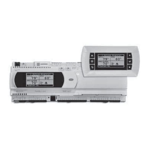
Remote Display Panel (if equipped)
A touch pad display panel allows for remote monitoring
and adjustment of parameters, allowing ease of control
access without going outdoors.
WARNING
Electrical shock hazard. Can cause personal injury or
equipment damage. Service must be performed only
by personnel that are knowledgeable in the operation
of the equipment being controlled.
WARNING
Mechanical high static protection cutoffs must
be installed by others to protect the system and
equipment from over-pressurization when using
factory provided control sensors. The manufacturer
does not assume responsibility for this.
Microprocessor Controller for DOAS
Document 483586
1
Advertisement
Table of Contents

Related Manuals for Greenheck Microprocessor Controller


Summary of Contents for Greenheck Microprocessor Controller
- Page 1 Occupancy Modes button keypad. The microprocessor controller offers three modes of Pre-Programmed Operating Sequences determining occupancy: a digital input, the internal time clock or the BMS. If in the unoccupied mode, the unit...
-
Page 2: Table Of Contents
Unit Configuration ....34 Alarms ..... . 35 Microprocessor Controller for DOAS ®... -
Page 3: Sequence Of Operation
Sequence of Operation The microprocessor controller can be configured for UNIT/SYSTEM DISABLED COMMAND: air handler, energy recovery, and dedicated outdoor air The unit becomes disabled due to the following: systems. Each application utilizes similar technologies • The unit was disabled from the controller’s Unit for heating and cooling: chilled water, hot water, indirect Enable screen. -
Page 4: Setpoint Control (Occupied)
• Hot Water Coil: Microprocessor controller will • Outdoor Air Temperature Reset Function: The modulate a hot water valve (provided by others) to controller will default to supply temperature reset maintain the supply temperature setpoint. -
Page 5: Economizer
• Modulating Hot Gas Reheat (valve): The comparison of the building static pressure setpoint to microprocessor controller will modulate the hot gas the actual building static pressure level reported from reheat valve to maintain the supply temperature the sensor. -
Page 6: Oa And Recirc Air Damper Control
After the defrost cycle time, the supply fan and tempering are re-energized to continue normal operation. The controller will not allow another defrost cycle for a minimum normal operating cycle time (30 minutes). Microprocessor Controller for DOAS ®... -
Page 7: Alarms
Sequence of Operation Alarms The microprocessor controller includes a digital output for remote indication of an alarm condition, which connects via the J15 port. Possible alarms include: • Dirty Filter Alarm: If the outside air or return air filter differential pressure rises above the differential pressure switch setpoint, the microprocessor controller will activate an alarm. -
Page 8: Large Controller
ID14 2 Speed Fan Input ID17 ID14H NC13 2 Position Damper Input ID18 IDC17 Optional Modbus RTU/BACnet MSTP connections Optional LonWorks cards are are made to the J26 FBus2 terminal. located in BMS Card port. Microprocessor Controller for DOAS ®... -
Page 9: Medium Controller
Condensate Drain Pan Switch IDC13 NO13 Remote Start Input ID14 ID17 ID14H NC13 ID18 IDC17 Optional LonWorks cards are Optional Modbus RTU/BACnet MSTP connections located in BMS Card port. are made to the J26 FBus2 terminal. Microprocessor Controller for DOAS ®... -
Page 10: C.pcoe - Expansion Board Overview, Medium
Space Static Pressure Preheater Enable Supply Air Duct Static Pressure Space Setpoint Adjustment The expansion board is an I/O module than can be used to monitor additional statuses or provide commands from medium board controller. Microprocessor Controller for DOAS ®... -
Page 11: Pcoe - 4:1 Furnace
Main Gas Valve - Small Manifold Main Gas Valve - Large Manifold High Speed Fan Ignition Controller Alarm 24 VAC 24 VAC for Analog Outputs Ignition Controller - Large Manifold Modulating Gas Valve 24 VAC Modbus Connection Modbus Address Switches Microprocessor Controller for DOAS ®... -
Page 12: Display Use
Display Use The microprocessor controller is located in the unit control center. The face of the controller has six buttons, allowing the user to view unit conditions and alter parameters. The microprocessor controller is pre-programmed with easy to use menus. A remote display is also available, which connects via the J10 port. A six wire patch cable is needed. -
Page 13: Example Of Web User Interface
Information – Provides manufacturer support information as well as IOM resources. Service – User must be logged with service access criteria (9998). Once proper login is established, the user can view configured input/output points associated with the unit controller Microprocessor Controller for DOAS ®... -
Page 14: Main Menu
Backup/Restore Reference the Advanced menu IO Status/Offset* section for more information. IO Config *Consult Unit Config factory for more information. Unit Settings* Service Info* Alarm Shutdown Management Alarms General Alarms Microprocessor Controller for DOAS ®... -
Page 15: Unit Status Overview
Unit Status Overview The microprocessor controller will revert to a default main menu loop. This loop includes several screens to view the operating conditions of the unit. Scroll through the menu screens by using the buttons. HE INITIAL MENU SCREEN DISPLAYS THE JOB NAME... - Page 16 Ramp Output screen will be active if the unit is configured for CO control. This screen displays the CO setpoint, CO level from the space, and the status of the control ramp. NERGY ECOVERY HEEL TATUS This screen provides overall status of the energy recovery wheel. Microprocessor Controller for DOAS ®...
- Page 17 Status points include controller output ramp, static pressure in the duct, and the duct static pressure setpoint. Similar status screen will appear for the exhaust fan if the unit is configured for exhaust fan duct static control. Microprocessor Controller for DOAS ®...
-
Page 18: Unit Enable
Reference Outside Setpoints for minimum and maximum outside air limits. Outdoor Air Reset Function 75° 70° 65° 60° 55° 50° 45° 50° 55° 60° 65° 70° Outside Air Temperature (°F) Microprocessor Controller for DOAS ®... - Page 19 This screen displays the delay time after the fans have started and tempering begins OOLING OCKOUT This screen displays the cooling lockout temperature. Cooling will be disabled when outside air is below the cooling lockout temperature (55ºF). Microprocessor Controller for DOAS ®...
-
Page 20: Dehumidification
The above dehumidification modes marked with an * indicate availability during unoccupied mode. The unoccupied dehumidification mode can be set differently than the occupied dehumidification mode. Reference Ctrl Variables/Advanced/ Unit Config/Unit Configuration Unoccupied Dehum Call for dehumidification method options. Microprocessor Controller for DOAS ®... - Page 21 To disable this operation and allow the compressor to cycle in dehumidification mode, uncheck the applicable cooling ramps. Microprocessor Controller for DOAS ®...
-
Page 22: Refrigeration
2 Position – Damper position is reset to “2-Pos/Max Econ:” set point when a contact closure is made. The 2-position damper operation can also be setup to bring the unit into temporary occupied mode until the contact is broken (Max Ventilation Mode - enabled in manufacturer menu settings). Microprocessor Controller for DOAS ®... - Page 23 If enabled, the OA damper and recirculation damper will not modulate during economize. Instead, only the energy recovery wheel will be stopped to ensure no energy is transferred from the supply airstream and exhaust airstream. Microprocessor Controller for DOAS ®...
-
Page 24: Energy Recovery
This screen display the energy recovery wheel jog function. This screen only appears if the unit has an energy recovery wheel and stop wheel economizer method for control. Momentarily enables the wheel in order to expose a new section to the airstream. Microprocessor Controller for DOAS ®... -
Page 25: Fan Control Supply Fans Control
• Tempering outputs immediately revert back to their off value; while • Dampers remain open and fans continue to run; until - The supply air temperature falls below the soft shutdown enable setpoint minus 5.0ºF; or - The soft shutdown delay timer has expired. Microprocessor Controller for DOAS ®... -
Page 26: Exhaust Fans Control
Outdoor Air Damper Tracking – The exhaust fan will proportionally track the outdoor air damper, between a minimum and maximum position. Return Duct Static Pressure – Fan speed is determined by duct pressure control loop. Microprocessor Controller for DOAS ®... -
Page 27: Occupancy
This screen only appears if unit is provided with unoccupied recirculation. This screen allows the user to enable/disable modes of operation when in unoccupied recirculation control. HIS SCREEN DISPLAYS OCCUPANCY OVERRIDE CONDITIONS Screen allows the user to override occupancy for a set duration. Microprocessor Controller for DOAS ®... -
Page 28: Advanced Manual Overrides
The speed is the proportional percentage of the analog output from the controller to the VFD. 0% Speed = Min speed (determined by VFD) 100% Speed = Max speed (determined by VFD) (Reference unit Installation and Operation Manual for VFD programming). Microprocessor Controller for DOAS ®... - Page 29 HIS SCREEN ALLOWS THE USER TO VERRIDE THE LECTRIC EATER PERATION This screen only appears if the unit is equipped with electric post heat. Electric heater percentage is directly proportional to the 0 – 10 VDC output signal. Microprocessor Controller for DOAS ®...
-
Page 30: Network Settings
HIS SCREEN ALLOWS THE USER TO IEW AND DJUST ONTROLLER ONFIG ETTINGS This screen will appear if the unit is set for BACnet IP and allows the user to set the device and port settings. Microprocessor Controller for DOAS ®... - Page 31 BMS point. Reference Points List above and in the Appendix for more detailed point information. Screen to the left is an example of the sensor source type. Source can be set for local or BMS at this screen. Microprocessor Controller for DOAS ®...
-
Page 32: Backup/Restore
(internal memory or USB). If creating a backup to a USB drive, insert a USB drive into the main controller. 5. Press Enter to highlight and then the Up or Down arrow buttons to fill the Save checkbox. This action creates the backup file. Microprocessor Controller for DOAS ®... - Page 33 5. Press Enter to highlight and then the Up or Down arrow buttons to fill the Restore checkbox. This action restores the backup file. If there is an error during the process, the specific error is displayed on this screen. 6. Cycle power to the controller. Microprocessor Controller for DOAS ®...
-
Page 34: I/O Configuration
Note: An askterisk indicates method is only available if the unit is equipped with an unoccupied recirculation damper. HIS SCREEN ALLOWS THE USER TO NABLE ORNING P AND The user can enable morning warm up, morning cool down, and set the duration for the sequence. Microprocessor Controller for DOAS ®... -
Page 35: Alarms
Check for high limit trip. IG offline Indicates communication with furnace control has failed. Alarm only IG Lg Man No Flame AL No flame after 3 trials for ignition on the large manifold. Alarm only Microprocessor Controller for DOAS ®... -
Page 36: Appendix Remote Display
If making your own cable, use the same pin-out for each end. NTC Temperature Sensor Chart Resistance (k ) Microprocessor Controller for DOAS ®... -
Page 37: I/O Expansion Board Quick Start
I/O expansion board. See example to the left. Viewing c.PCOe Auxiliary Values – Once the expansion board I/O is configured, the user can view and/or change the I/O type by navigating to Ctrl Variables/Aux I/O Config. Microprocessor Controller for DOAS ®... -
Page 38: Room Thermostat Quick Start
The sensors must all be connected in a daisy chain configuration. The microprocessor controller will be pre-configured for one room thermostat. If room temperature averaging is desired, additional field setup will be required both in the controller and on the Modbus room sensors: •... - Page 39 • To adjust the temperature override time, enter the following menu options at the controller, Cntrl Variables/Occupancy. Scroll down at the Occupancy Menu and select Occ Timed Override. This menu will allow the user to enable occupancy override from the controller and set override duration. Microprocessor Controller for DOAS ®...
-
Page 40: Greentrol ® Airflow Monitoring Quick Start
Up/Down Button Function - The Up/Down buttons are used to navigate the menu and to change values in the menu. Esc Button Function - The ESC button allows the user to exit the current menu or function. Microprocessor Controller for DOAS ®... -
Page 41: Points List
Customer defined auxiliary ReadCOV_ Aux_In_Customer_3 30643 Input input NoWrite Customer defined auxiliary ReadCOV_ Aux_In_Customer_4 30645 Input input NoWrite Customer defined auxiliary ReadCOV_ Aux_In_Customer_5 30647 Input input NoWrite Customer defined auxiliary ReadCOV_ Aux_In_Customer_6 30649 Input input NoWrite Microprocessor Controller for DOAS ®... - Page 42 Commandable is set to BMS. Cooling_Lockout_ Cooling Ambient Lockout ReadCOV_ 40061 Holding Setpoint Setpoint Commandable Heating_Lockout_ Heating Ambient Lockout ReadCOV_ 40063 Holding Setpoint Setpoint Commandable Space_Static_ Space Static Pressure ReadCOV_ 40073 Holding Pressure_Setpoint Setpoint Commandable Microprocessor Controller for DOAS ®...
- Page 43 Commandable Aux_BMS_Analog_ BMS Commanded auxilary ReadCOV_ 40095 Holding Output_2 analog output Commandable Aux_BMS_Analog_ BMS Commanded auxilary ReadCOV_ 40097 Holding Output_3 analog output Commandable Aux_BMS_Analog_ BMS Commanded auxilary ReadCOV_ 40099 Holding Output_4 analog output Commandable Microprocessor Controller for DOAS ®...
- Page 44 NoWrite ReadCOV_ Space_Enthalpy Space Enthalpy 30099 Input NoWrite Total_Exhaust_Fan_ ReadCOV_ Total Exhaust Fan CFM 30135 Input CFM_BMS NoWrite ReadCOV_ OAD_CFM_BMS OAD CFM 30173 Input NoWrite OAD_Space_Static_ ReadCOV_ OAD Static Pressure Ramp 30177 Input Pressure_Ramp NoWrite Microprocessor Controller for DOAS ®...
- Page 45 ReadCOV_ Compressor_Analog_ 30585 Input Analog Output - Valent BMS NoWrite Output_BMS Circuit_A_Sat_ Circuit A Saturated ReadCOV_ Discharge_ 30587 Input Discharge Temperature NoWrite Temperature Circuit_B_Sat_ Circuit B Saturated ReadCOV_ Discharge_ 30589 Input Discharge Temperature NoWrite Temperature Microprocessor Controller for DOAS ®...
- Page 46 Allows the BMS to control EF_Control_Source_ Read_ exhaust fan speed. True = Local Coil Commandable BMS. False = Local. Allows the BMS to control OAD_Control_Source_ Read_ OAD position. True = BMS. Local Coil Commandable False = Local. Microprocessor Controller for DOAS ®...
- Page 47 ReadCOV_ Active Inactive 10164 Discrete Enable_Digital_Output Digital Output NoWrite Compressor_2_ Compressor 2 Enable ReadCOV_ Active Inactive 10165 Discrete Enable_Digital_Output Digital Output NoWrite Compressor_3_ Compressor 3 Enable ReadCOV_ Active Inactive 10166 Discrete Enable_Digital_Output Digital Output NoWrite Microprocessor Controller for DOAS ®...
- Page 48 Discrete Sensor_Alarm.Active Alarm (0=Normal 1=Alarm) NoWrite Shutdown_Input_ Shutdown Input Alarm ReadCOV_ Alarm Normal 10496 Discrete Alarm.Active (0=Normal 1=Alarm) NoWrite Supply_Air_Temp_ Supply Air Temp Low Limit ReadCOV_ Alarm Normal 10501 Discrete Low_Limit.Active Alarm (0=Normal 1=Alarm) NoWrite Microprocessor Controller for DOAS ®...
- Page 49 (0=Normal 1=Alarm) Compressor Envelope - Al_LowRatioP_ ReadCOV_ Low Pressure Ratio Alarm Alarm Normal 10559 Discrete COMP_1.Active NoWrite (0=Normal 1=Alarm) Low Suction Refrigerant Al_LowSuct_A_EVD_1. ReadCOV_ Temperature - Valve 1 Alarm Normal 10560 Discrete Active NoWrite (0=Normal 1=Alarm) Microprocessor Controller for DOAS ®...
- Page 50 Time before 30183 Input Remaining NoWrite starting supply fan. Exhaust Fan startup Exhaust_Fan_Delay_ ReadCOV_ sequence. Time before 30185 Input Remaining NoWrite starting exhaust fan. Most recent alarm. See ReadCOV_ LatestAlm 30193 Input alarm table. NoWrite Microprocessor Controller for DOAS ®...
- Page 51 Discrete Digital_Input Input Status NoWrite EAD_End_Switch_ Exhaust Air Damper End ReadCOV_ Active Inactive 10071 Discrete Digital_Input Switch Digital Input Status NoWrite OAD_End_Switch_ OAD End Switch Digital ReadCOV_ Active Inactive 10101 Discrete Digital_Input Input Status NoWrite Microprocessor Controller for DOAS ®...
- Page 52 10391 Discrete Active (0=Normal 1=Alarm) NoWrite Mixed_Temperature_ Mixed Temperature Sensor ReadCOV_ Alarm Normal 10452 Discrete Sensor_Alarm.Active Alarm (0=Normal 1=Alarm) NoWrite OAD_AMD_analog_ OAD CFM Analog Input ReadCOV_ Alarm Normal 10456 Discrete input_Alarm.Active Alarm (0=Normal 1=Alarm) NoWrite Microprocessor Controller for DOAS ®...
-
Page 53: Modbus Connections
Appendix: Factory ModBus Connections Microprocessor Controller for DOAS ®... -
Page 54: Maintenance Log
Date ___________________Time _____________ AM/PM Notes: ___________________________________________ Notes: ___________________________________________ _________________________________________________ _________________________________________________ _________________________________________________ _________________________________________________ _________________________________________________ _________________________________________________ _________________________________________________ _________________________________________________ Date ___________________Time _____________ AM/PM Date ___________________Time _____________ AM/PM Notes: ___________________________________________ Notes: ___________________________________________ _________________________________________________ _________________________________________________ _________________________________________________ _________________________________________________ _________________________________________________ _________________________________________________ _________________________________________________ _________________________________________________ Microprocessor Controller for DOAS ®... - Page 55 Date ___________________Time _____________ AM/PM Notes: ___________________________________________ Notes: ___________________________________________ _________________________________________________ _________________________________________________ _________________________________________________ _________________________________________________ _________________________________________________ _________________________________________________ _________________________________________________ _________________________________________________ Date ___________________Time _____________ AM/PM Date ___________________Time _____________ AM/PM Notes: ___________________________________________ Notes: ___________________________________________ _________________________________________________ _________________________________________________ _________________________________________________ _________________________________________________ _________________________________________________ _________________________________________________ _________________________________________________ _________________________________________________ Microprocessor Controller for DOAS ®...
-
Page 56: Our Commitment
Our Commitment As a result of our commitment to continuous improvement, Greenheck reserves the right to change specifications without notice. Specific Greenheck product warranties are located on greenheck.com within the product area tabs and in the Library under Warranties. AMCA Publication 410-96, Safety Practices for Users and Installers of Industrial and Commercial Fans, provides additional safety information.