Table of Contents
Advertisement
Note: Please use this manual together with service manual
Model No.[SC-HTB550PCK, Order No.PSG1202001CE].
TABLE OF CONTENTS
1 Safety Precautions----------------------------------------------- 3
1.1. General Guidelines---------------------------------------- 3
1.2. Before Repair and Adjustment ------------------------- 4
1.3. Protection Circuitry ---------------------------------------- 4
1.4. Caution For Fuse Replacement------------------------ 4
1.5. Caution For SMPS Module------------------------------ 4
1.6. Safety Part Information----------------------------------- 5
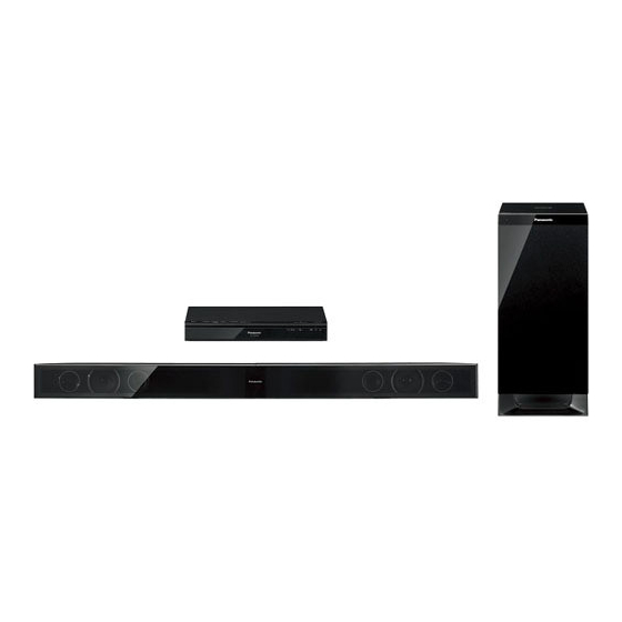
Home Theater Audio System
Model No.
Product Color: (K)...Black Type
PAGE
1.7. Safety Installation Instructions -------------------------6
2 Warning --------------------------------------------------------------7
to Electrostatically Sensitive (ES) Devices ----------7
3 Service Navigation -----------------------------------------------9
3.1. Service Information ----------------------------------------9
© Panasonic Corporation 2012. All rights reserved.
Unauthorized copying and distribution is a violation of
law.
SU-HTB550PH
SB-HTB550P
SB-HWA520PH
SC-HTB550PH
PSG1204036AE
PAGE
Advertisement
Table of Contents

Related Manuals for Panasonic SU-HTB550PH


Summary of Contents for Panasonic SU-HTB550PH
-
Page 1: Table Of Contents
2.2. Service caution based on Legal restrictions --------8 1.5. Caution For SMPS Module------------------------------ 4 3 Service Navigation -----------------------------------------------9 1.6. Safety Part Information----------------------------------- 5 3.1. Service Information ----------------------------------------9 © Panasonic Corporation 2012. All rights reserved. Unauthorized copying and distribution is a violation of law. - Page 2 3.2. Notes -------------------------------------------------------- 10 3.3. Different Points ------------------------------------------- 11 4 Specifications ---------------------------------------------------- 14 5 Block Diagram --------------------------------------------------- 15 5.1. Main Unit (SU-HTB550) -------------------------------- 15 5.2. Active Subwoofer (SB-HWA520)--------------------- 19 6 Schematic Diagram--------------------------------------------- 20 6.1. Main Unit (SU-HTB550) -------------------------------- 20 6.2. Active Subwoofer (SB-HWA520)--------------------- 26 7 Printed Circuit Board ------------------------------------------ 29 7.1.
-
Page 3: Safety Precautions
1 Safety Precautions 1.1. General Guidelines 1. When servicing, observe the original lead dress. If a short circuit is found, replace all parts which have been overheated or damaged by the short circuit. 2. After servicing, ensure that all the protective devices such as insulation barriers, insulation papers shields are properly installed. -
Page 4: Before Repair And Adjustment
1.2. Before Repair and Adjustment Main Unit (SU-HTB550) Disconnect AC power, discharge unit AC Capacitors as such C5700, C5701, C5702, C5703 and C5705 through a 10W, 1W resistor to ground. Caution : DO NOT SHORT-CIRCUIT DIRECTLY (with a screwdriver blade, for instance), as this may destroy solid state devices. After repairs are completed, restore power gradually using a variac, to avoid overcurrent. -
Page 5: Safety Part Information
1.6. Safety Part Information Safety Parts List: There are special components used in this equipment which are important for safety. These parts are marked by in the Schematic Diagrams & Replacement Parts List. It is essential that these critical parts should be replaced with manufacturer’s specified parts to prevent shock, fire or other hazards. -
Page 6: Safety Installation Instructions
1.7. Safety Installation Instructions... -
Page 7: Warning
2 Warning 2.1. Prevention of Electro Static Discharge (ESD) to Electrostatically Sensi- tive (ES) Devices Some semiconductor (solid state) devices can be damaged easily by electricity. Such components commonly are called Electrostat- ically Sensitive (ES) Devices. Examples of typical ES devices are integrated circuits and some field-effect transistors and semicon- ductor “chip”... -
Page 8: Service Caution Based On Legal Restrictions
2.2. Service caution based on Legal restrictions 2.2.1. General description about Lead Free Solder (PbF) The lead free solder has been used in the mounting process of all electrical components on the printed circuit boards used for this equipment in considering the globally environmental conservation. The normal solder is the alloy of tin (Sn) and lead (Pb). -
Page 9: Service Navigation
3 Service Navigation 3.1. Service Information This service manual contains technical information which will allow service personnel’s to understand and service this model. Please place orders using the parts list and not the drawing reference numbers. If the circuit is changed or modified, this information will be followed by supplement service manual to be filed with original service manual. -
Page 10: Notes
3.2. Notes This service manual contains technical information which will allow service personnel’s to understand and service this model. Please place orders using the parts list and not the drawing reference numbers. If the circuit is changed or modified, this information will be followed by supplement service manual to be filed with original service manual. -
Page 11: Different Points
3.3. Different Points 3.3.1. Main Unit (SU-HTB550) Ref. No. Parts No. Parts name & Description Remarks SU-HTB550PCK SU-HTB550PHK RGR0423B-B2 RGR0423B-G REAR PANEL RYP1694-K RYP1694D-K FRONT PANEL ASSY RGU2775-K RGU2775-K1 VOLUME BUTTON C2101 F1G1H101A565 100pF 50V C2102 F1G1H101A565 100pF 50V C2105 F1G0J105A031 6.3V C2106... - Page 12 Ref. No. Parts No. Parts name & Description Remarks SU-HTB550PCK SU-HTB550PHK R2106 ERJ2GEJ223X 1/16W R2107 ERJ2GEJ154X 150K 1/16W R2108 ERJ2GEJ154X 150K 1/16W R2109 ERJ2GEJ154X 150K 1/16W R2110 ERJ2GEJ154X 150K 1/16W R2111 ERJ2GEJ472X 4.7K 1/16W R2112 ERJ2GEJ472X 4.7K 1/16W R2113 ERJ2GEJ101X 1/16W R2114 ERJ2GEJ101X...
- Page 13 Ref. No. Parts No. Parts name & Description Remarks SC-HTB550PCK SC-HTB550PHK RPFX1044GN RPF0588 MIRAMAT BAG (SB-HWA)
-
Page 14: Specifications
4 Specifications Dimensions (W x H x D) 956 mm x 75 mm x 35 mm Mass 1.54 kg Amplifier Section Vertical placement using the speaker bases RMS Output Power Dimensions (W x H x D) 148 mm x 528 mm x 145 mm 10% total harmonic distortion Mass 0.88 kg... -
Page 15: Block Diagram
DC DET S DET S DET S DET SYNC SYNC AC SYNC FROM/TO SD OUT SD OUT SD OUT POWER SUPPLY PCONT PCONT PCONT HDMI PCONT HDMI PCONT HDMI PCONT ECO PCONT ECO PCONT ECO PCONT SC-HTB550PH(SU-HTB550PH) SYSTEM CONTROL BLOCK DIAGRAM... - Page 16 CN2201 CN5200 VALID VALID CN2201 CN5200 CN2201 CN5200 CN2201 CN5200 DC DET DC DET DC DET DC DETECT DC DET PVCC CIRCUIT Q5802,Q5803 Q5804,Q5805 CN2201 CN5200 ECO LEVEL ECO LEVEL ECO LEVEL ECO LEVEL D5803 D5804 SC-HTB550PH(SU-HTB550PH) AUDIO BLOCK DIAGRAM...
- Page 17 REG3.3V 34,35 PC5720 FEEDBACK SD OUT CN2202 SD OUT SD OUT SD OUT FROM FEEDBACK SYSTEM CONTROL ECO CONT CN2202 ECO CONT ECO PCONT ECO PCONT CIRCUIT IC5801 C0DABYY00011 SHUNT REGULATOR Q5863 PRIMARY SECONDARY SC-HTB550PH(SU-HTB550PH) POWER SUPPLY (1/2) BLOCK DIAGRAM...
- Page 18 VOUT 2 REG12V 1 VIN ADJ 4 PANEL P.C.B. REG5V REG3.3V REG3.3V 3.3V IC2902 C0CBCAG00015 +1.8V VOLTAGE D2903 REGULATOR TO POWER SUPPLY REG3.3V 1 IN REG1.8V REG1.8V BLOCK (1/2) 1.8V OUT 3 REG3.3V 2 ON/OFF SC-HTB550PH(SU-HTB550PH) POWER SUPPLY (2/2) BLOCK DIAGRAM...
-
Page 19: Active Subwoofer (Sb-Hwa520)
LINK LINK LED CN1000 CH2 R OUT CH2 IN RCH SPEAKER BOOT2 15 CN1005 OUT2 14 SUBWOOFER CN1005 OUT1 10 CN1000 BOOT1 9 SU-HTB550PH DIGITAL Q1004 FREQUENCY RECEIVER +5V POWER CIRCUIT SUPPLY SWITCH Q1005 RF PCONT CN1000 PCONT PCONT SWITCH... -
Page 20: Schematic Diagram
N.C. N.C. S_DET N.C. HDMI_PCONT HD: MAIN (HDMI) CIRCUIT: SCHEMATIC DIAGRAM - 1 ~ 4 SC-HTB550PH (SU-HTB550PH) CP: MAIN (CPU) CIRCUIT: SCHEMATIC DIAGRAM - 5 ~ 6 DP: MAIN (DSP) CIRCUIT: SCHEMATIC DIAGRAM - 7 ~ 8 MAIN (CPU) CIRCUIT... - Page 21 DP: MAIN (DSP) CIRCUIT: SCHEMATIC DIAGRAM - 7 ~ 8 C2827 C2824 C2823 6.3V330 6.3V330 QR2801 6.3V330 HDMI_GND K213 ...PH K113 ...PH CL223 CL123 SC-HTB550PH (SU-HTB550PH) HD HDMI_1.8V MAIN (CPU) CIRCUIT NOTE: “ * ” REF IS FOR INDICATION ONLY...
- Page 22 C1AB00003174 DIGITAL AUDIO INTERFACE RECEIVER CS_CODEC RESET_CODEC SC-HTB550PH (SU-HTB550PH) HD: MAIN (HDMI) CIRCUIT: SCHEMATIC DIAGRAM - 1 ~ 4 CP: MAIN (CPU) CIRCUIT: SCHEMATIC DIAGRAM - 5 ~ 6 MAIN (DSP) CIRCUIT DP: MAIN (DSP) CIRCUIT: SCHEMATIC DIAGRAM - 7 ~ 8...
- Page 23 DSP_SCLK DSP_LRCLK DSP_LRCLK DSP_MCLK DSP_MCLK SC-HTB550PH (SU-HTB550PH) HD: MAIN (HDMI) CIRCUIT: SCHEMATIC DIAGRAM - 1 ~ 4 CP: MAIN (CPU) CIRCUIT: SCHEMATIC DIAGRAM - 5 ~ 6 DP: MAIN (DSP) CIRCUIT: SCHEMATIC DIAGRAM - 7 ~ 8 MAIN (DSP) CIRCUIT...
- Page 24 MAIN (CPU) R3007 CIRCUIT (CN2205) R3006 IN SCHEMATIC R3005 DIAGRAM - 6 R3004 C3001 100P RF+5V R3003 RF+5V C3003 LB3014 RF_GND 6.3V220 J0JBC0000015 RF_GND WM_DET C3000 R3013 0.01 ET3000* SC-HTB550PH (SU-HTB550PH) PANEL / BUTTON / POWER BUTTON / WIRELESS ADAPTER CIRCUIT...
- Page 25 SWITCH Q5761 R5728 ECO CONTROL R5869 R5819 R5805 C5760 C5761 B1ABCN000001 Q5864 C5819 OP-AMP R5817 B1ABGC000001 R5868 C5870 R5861 2.2K R5767 C5828 100K R5818 SWITCH 6.3V470 2.2K SC-HTB550PH (SU-HTB550PH) NOTE: “ * ” REF IS FOR INDICATION ONLY SMPS CIRCUIT...
-
Page 26: Active Subwoofer (Sb-Hwa520)
6.2. Active Subwoofer (SB-HWA520) 6.2.1. DAMP CIRCUIT (1/2) SCHEMATIC DIAGRAM - 13 DAMP CIRCUIT : +B SIGNAL LINE : -B SIGNAL LINE : AUDIO OUTPUT SIGNAL LINE R1000 CN1002 150K IDSET POWER BUTTON +5V_GND CIRCUIT (H1004*) POWER_SW IN SCHEMATIC MODE_SW MODE_SW DIAGRAM - 15 Z1000... - Page 27 6.2.2. DAMP CIRCUIT (2/2) SCHEMATIC DIAGRAM - 14 DAMP CIRCUIT : +B SIGNAL LINE : -B SIGNAL LINE : AUDIO OUTPUT SIGNAL LINE IC5200 R1009 C1BA00000497 Q1004 4.7K POWER AMPLIFIER B1ADCE000012 +5V POWER SUPPLY R5204 R1007 1.5K 1.2K Q1005 B1GBCFJJ0051 PCONT SWITCH C1012 R1015...
- Page 28 6.2.3. POWER BUTTON & AC INLET CIRCUIT SCHEMATIC DIAGRAM - 15 POWER BUTTON CIRCUIT AC INLET CIRCUIT S1000 H1004* I/D SET (RED) IDSET P5701 DAMP CIRCUIT TL10* +5V_GND (CN1002) POWER_SW AC IN IN SCHEMATIC TO SMPS MODULE MODE_SW 110V ~ 240V DIAGRAM - 13 50/60Hz S1001...
-
Page 29: Printed Circuit Board
VA2511 LB2504 C2528 R2521 R2525 C2553 R2507 LB2506 R2504 R2512 C2509 R2526 C2506 VA2513 C2508 R2510 LB2502 LB2501 VA2510 IC2502 PbF 3519A-1 3519A-1 R2295 R2296 (SIDE A) SC-HTB550PH (SU-HTB550PH) MAIN P.C.B. NOTE: " * " REF IS FOR INDICATION ONLY... - Page 30 L2805 L2801 L2803 L2802 CN2202 IC2501 C2531 C2804 HDMI AV OUT (TV (ARC)) LB2801 D2321 R2546 R2545 CN2201 C2526 RX2501 R2542 R2538 PbF 3519A-1 3519A-1 (SIDE B) SC-HTB550PH (SU-HTB550PH) NOTE: " * " REF IS FOR INDICATION ONLY MAIN P.C.B.
- Page 31 R6006 R6007 (SELECTOR) (VOL DOWN) PbF 3558AB 3558AB JW6003 POWER BUTTON P.C.B. (REP4792BC) S6001 (POWER) JW6004 PbF 3558AC 3558AC SC-HTB550PH (SU-HTB550PH) NOTE: " * " REF IS FOR INDICATION ONLY PANEL / BUTTON / POWER BUTTON / WIRELESS ADAPTER P.C.B.
- Page 32 PC5720 T3.15A 250V R5862 C5897 R5864 C5791 3521AA-2 3521AA-2 ZA1* (HEATSINK) D5812 QR5862 R5801 CAUTION RISK OF ELECTRIC SHOCK AC VOLTAGE LINE. PLEASE DO NOT TOUCH THIS P.C.B SC-HTB550PH (SU-HTB550PH) NOTE: " " REF IS FOR INDICATION ONLY SMPS P.C.B.
-
Page 33: Active Subwoofer (Sb-Hwa520)
7.2. Active Subwoofer (SB-HWA520) 7.2.1. DAMP / POWER BUTTON / AC INLET P.C.B. DAMP P.C.B. (REP4806BA) IC3002 Q1004 R1000 R5204 W1026 Z1003 W1027 CN1002 C3205 W1003 R1008 K1051...PH C3105 R1007 R3206 R3108 Q1007 C1000 Q1006 W1020 Z1000 C1010 R1034 C5221 Q1005 HEATSINK* W1022... -
Page 34: Exploded View And Replacement Parts List
8 Exploded View and Replacement Parts List 8.1. Exploded View and Mechanical replacement Parts List 8.1.1. Cabinet Parts Location (SU-HTB550) *HEAT SINK UNIT A P5701 ZJ5701 *HEAT SINK UNIT B T5701 *DAMP HEAT SINK UNIT JK2601 ZJ5703 CN2301 JK2701 CN3001 (WIRELESS JK2501 (SMPS P.C.B.) - Page 35 8.1.2. Cabinet Parts Location (SB-HTB550) STANDING POSITION BAR POSITION (FRONT SPEAKER UNIT L/R) (FRONT SPEAKER UNIT (L/R)) A12-1 A12-1 A12-1 A12-1 A11-1 A12-1 A12-1 (FRONT SPEAKER UNIT (L)) A12-1 A12-1 (FRONT SPEAKER UNIT (R)) A11-1 A8-1 A8-1 A8-1 A8-1 A8-1 SB-HTB550P-K NOTE: "...
- Page 36 FRONT SPEAKER UNIT (L/R) REAR VIEW REAR VIEW SB-HTB550P-K CABINET DRAWINGS...
- Page 37 8.1.3. Cabinet Parts Location (SB-HWA520) (POWER BUTTON P.C.B.) *H1004 (D-AMP P.C.B.) Z1000 CN1002 Z1003 CN1000 CN1005 CN1003 *H1001 Z1001 Z1002 (DIGITAL RECEIVER MODULE P.C.B.) P5701 (AC INLET P.C.B.) *TL20 SP61 *TL10 (SMPS MODULE) 75-1 75-1 75-1 75-2 75-2 75-1 SB-HWA520PH1 NOTE: "...
- Page 38 8.1.4. Packaging (SC-HTB550) ACCESSORIES BAG SB-HTB550P REMOTE CONTROL AC CORD A1-1 R/C BATTERY COVER A10 SCREW OI BOOK (WALL HOOK) SU-HTB550PH A12 A12 SB-HWA520PH A4-1 A5-1 SB-HTB550P LEG SUPPORT UNIT A11-1 LEG FELT POLYFOAM (TOP) POLYFOAM (LEFT) POLYFOAM (BOTTOM) POLYFOAM (RIGHT)
- Page 39 8.1.5. Mechanical Replacement Parts List 8.1.5.1. Main Unit (SU-HTB550) Safety Ref. Part No. Part Name & QTY Remarks Description RMK0804 BOTTOM CHASSIS RMQ2001 TRANSMITTER HOLDER 1 Safety Ref. Part No. Part Name & QTY Remarks RMQ2003 VOLUME BUTTON Description BRACKET CABINET AND CHAS- RMZ1105 HEAT SINK SPACER...
- Page 40 8.1.5.4. Packaging & Accessories Safety Ref. Part No. Part Name & QTY Remarks Description (SC-HTB550) RML0754 DOCKING ARM RMF0546 EPT SEALER RGK2305-K FRONT ORNAMENT Safety Ref. Part No. Part Name & QTY Remarks RML0755 SUPPORT ARM Description PACKING MATERIALS SPEAKERS RPG9866 PACKING CASE L0AZ03A00014 TWEETER SPEAKER...
-
Page 41: Electrical Replacement Parts List
8.2. Electrical Replacement Parts List 8.2.1. Main Unit (SU-HTB550) Safety Ref. Part No. Part Name & QTY Remarks Description TH5702 D4CAA5R10001 THERMISTOR Safety Ref. Part No. Part Name & QTY Remarks Description PRINTED CIRCUITS JACKS BOARDS P5701 K2AA2B000011 AC INLET PCB1 REP4735D MAIN P.C.B. - Page 42 8.2.2. Active Subwoofer (SB-HWA520) Safety Ref. Part No. Part Name & QTY Remarks Description PCB15 N0AE3ZJ00001 SMPS MODULE P.C.B. 1 PCB16 REP4814A DIGITAL RECEIVER Safety Ref. Part No. Part Name & QTY Remarks MODULE P.C.B. Description PRINTED CIRCUITS BOARDS JACK PCB11 REP4806BA DAMP P.C.B.