Table of Contents
Advertisement
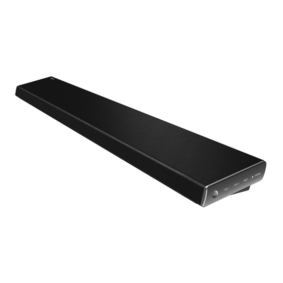
SB-HWA690
Remote
Control
This service information is designed for experienced repair technicians only and is not designed for use by the general
public. It does not contain warnings or cautions to advise non-technical individuals of potential dangers in attempting
to service a product. Products powered by electricity should be serviced or repaired only by experienced professional
technicians. Any attempt to service or repair the product or products dealt with in this service information by anyone else
could result in serious injury or death.
SU-HTB690
WARNING
Home Theater Audio System
SC-HTB690EB
Model No.
SC-HTB690EG
SU-HTB690EB
SU-HTB690EG
SB-HWA690E
Colour:(K)...........Black Type
© Panasonic Corporation 2015
Unauthorized copying and distribution is a violation of law.
ORDER NO.AD1503006CE
Advertisement
Table of Contents

Related Manuals for Panasonic SC-HTB690EB


Summary of Contents for Panasonic SC-HTB690EB
- Page 1 Any attempt to service or repair the product or products dealt with in this service information by anyone else could result in serious injury or death. © Panasonic Corporation 2015 Unauthorized copying and distribution is a violation of law.
-
Page 2: Table Of Contents
TABLE OF CONTENTS PAGE 1 Safety Precautions ----------------------------------------------- 3 1.1. General Guidelines ----------------------------------------- 3 1.2. Leakage Current Cold Check ----------------------------- 3 1.3. Leakage Current Hot Check (See Figure 1.) --------- 3 1.4. Protection Circuitry------------------------------------------- 3 2 Warning -------------------------------------------------------------- 4 2.1. Prevention of Electrostatic Discharge (ESD) to Electrostatically Sensitive (ES) Devices ------------ 4 2.2. -
Page 3: Safety Precautions
1 Safety Precautions 1.1. General Guidelines 1. IMPORTANT SAFETY NOTICE There are special components used in this equipment which are important for safety. These parts are marked by the Schematic Diagrams, Circuit Board Layout, Exploded Views and Replacement Parts List. It is essential that these critical parts should be replaced with manufacturer’s specified parts to prevent X-RADIATION, shock, fire, or other hazards. -
Page 4: Warning
2 Warning 2.1. Prevention of Electrostatic Discharge (ESD) to Electrostatically Sensitive (ES) Devices Some semiconductor (solid state) devices can be damaged easily by static electricity. Such components commonly are called Electrostatically Sensitive (ES) Devices. Examples of typical ES devices are IC(integrated circuits)and some field-effect transistors and semiconductor “chip”... -
Page 5: Caution For Ac Cord (For Eb)
1. Remove the Fuse Cover with a screwdriver. A replacement fuse cover can be purchased from your local Panasonic Dealer. If the fitted moulded plug is unsuitable for the socket outlet in your home then the fuse should be removed and the plug cut off and disposed of safety. -
Page 6: Service Caution Based On Legal Restrictions
2.3. Service Caution Based on Legal Restrictions 2.3.1 General Description About Lead Free Solder (PbF) The lead free solder has been used in the mounting process of all electrical components on the printed circuit boards used for thisequipment in considering the globally environmental conservation. The normal solder is the alloy of tin (Sn) and lead (Pb). -
Page 7: Service Navigation
3 Service Navigation 3.1. Service Information This service manual contains technical information, which allow service personnels to understand and service this model. Please place orders with the numbers in the parts list and not the numbers in the explossion illustration. If the circuit is changed or modified, the information will be followed by service manual to be controlled with original service manual. -
Page 8: Specifications
4 Specifications Power supply AMPLIFIER SECTION AC 220V to 240V, 50 Hz RMS output power (non-simultaneous drive) Dimensions (W x H x D) Front ch (L, R ch) Main unit 70W per channel (1kHz, 10%, 6Ω) For table top layout Centre ch (C ch) 950mm x 55mm x 120mm 70W per channel (1kHz, 10%, 6Ω) -
Page 9: Location Of Controls And Components
5 Location of Controls and Components Control reference guide This system (Front) - Page 10 This system (Rear)
- Page 11 Remote control INPUT SETUP SOUND ...
-
Page 12: Service Mode
6 Service Mode This unit has self-diagnosis function mode that provides errors information for service personnel. 6.1. Service Mode Table 1 Item FL Display Key operation Mode name Description Service Mode Enter into Service Mode Example: While Pressing and holding [VOL-] on the main unit, press [▼] [▲] on the remote control. -
Page 13: Service Mode Table
6.2. Service Mode Table 2 Item FL Display Key operation Mode name Description Model Name Display the Model name Example: In service mode: information Press [VOL+] button 3 times on HTB 690 MODEL: HTB XXX the remote control. The [SVC MODE]di spl ay w i l l appear after 3s, •... -
Page 14: Service Mode Region Display Table
6.3. Service Mode Region Display Table FL DISPLAY Position Region Display POS9 POS8 POS7 POS6 POS5 POS4 POS3 POS2 POS1 EB/EG/EE Reserve P,PC,PP Reserve Japan Reserve GN/GS/GT/PH/GK Reserve Reserve Reserve 6.4. Service Function Error Code Description of Error Code FL DISPLAY Position Diagnostic Contents error POS9 POS8 POS7 POS6 POS5 POS4 POS3 POS2 POS1... -
Page 15: Troubleshooting Guide
7 Troubleshooting Guide Main Unit (SU-HTB690) 7.1.1 No power No power No power Caution: Disconnect the AC cord Touch the Power No Display on = Check Fuse = = Check Fuse = button on the unit to button on the unit to Caution: display panel. - Page 16 No Key Function 7.1.4. No Key Function No Key Function 3.3 V Connect the AC at “STB_3V3” Change Touch PCB 3.3 V mains lead Connect the AC [Refer to check point ⑥] at “STB_3V3” Change Touch PCB mains lead [Refer to check point ⑥] Change Change Main PCB...
- Page 17 7.1.7. No Sound No Sound (Bluetooth®) 7.1.7.1. No Sound (Bluetooth®) If the pairing failure, Go to “Bluetooth® Pairing failure” Touch the Power 3.3 V Connect button to turn on Play sound No sound at “STB_3V3” Bluetooth® device the unit. [Refer to check point ⑥] No HDMI OUT No problem Go to...
- Page 18 7.1.9. Check Points POWER P.C.B. Output side of Fuse Pin1 of Rectifier Diode POWER P.C.B. +28V...
- Page 19 MAIN P.C.B. VFD_24V MAIN P.C.B. VDD3.3_OP AP3.3V_ D...
- Page 20 MAIN P.C.B. STB_3V3 HVDD HDMI_1.7V MAIN P.C.B. HB_HP_1...
-
Page 21: Active Subwoofer (Sb-Hwa690)
Active Subwoofer (SB-HWA690) 7.2.1 No power No power Caution: Press power button No Display on Disconnect the AC cord on the unit to turn on on the unit to turn on display panel. = Check Fuse = the unit. 0Ω = Check Rectifier Diode = = Check Power Transformer and at output side of Fuse. - Page 22 7.2.3. Check Points POWER P.C.B. Output side of Fuse Pin1 of Rectifier Diode POWER P.C.B. +32V...
-
Page 23: Wiring Connection And Voltage Data
8 Wiring Connection and Voltage Data Main Unit (SU-HTB690) L/C SPEAKER R SPEAKER SWITCH P.C.B. SWITCH P.C.B. 12.288M EEPROM HDMI OUT HDMI OUT HDMI IN AV8314A AV8314A HDMI P.C.B. HDMI P.C.B. BT MODULE WIRELESS P.C.B. WIRELESS P.C.B. 16Mb/FLASH 16Mb/FLASH OPTICAL MAIN P.C.B. - Page 24 VOLTAGE DATA (measurement status:Power On and No any external signal input ) PIN NO. VALUE PIN NO. VALUE 14.3V 5.2V 14.3V 5.2V 14.3V 14.3V PIN NO. VALUE 14.3V 3.3V CN207 14.3V 3.3V PIN NO. VALUE XP114 3.3V/0V XP114 1.7V PIN NO. VALUE 1.7V 1.17V...
- Page 25 PIN NO. VALUE PIN NO. VALUE 3.3V 3.3V XP112 0.02V 3.3V -1.2V 3.3V PIN NO. VALUE 3.3V 3.3V/0V 3.3V/0V 3.3V/0V 3.3V 3.3V 3.3V 3.3V 3.3V 0.02V 0.01V 3.3V PIN NO. VALUE 3.3V...
-
Page 26: Active Subwoofer (Sb-Hwa690)
Active Subwoofer (SB-HWA690) LED P C B LED P.C.B. AUDIO PROCESSOR SUBWOOFER TAS5342A TAS5342A TAS5534 TAS5534 WIRELESS WIRELESS P C B P.C.B. Switch Switch 3CG3906M PMOS DC-DC AP9561GM SY8292 Switch 3CG9012M AS1117 AS1117 MAIN P.C.B. CON501 CON501 POWER P.C.B. - Page 27 VOLTAGE DATA (measurement status:Power On and No any external signal input ) PIN NO. VALUE PIN NO. VALUE XP506 3.3V 3.3V 3.3V PIN NO. VALUE 0.14V 3.3V PIN NO. VALUE 3.3V 3.3V 3.3V 3.3V XP501 3.3V 3.3V 3.3V 1.5V 3.3V 5.1V 5.1V 1.6V...
-
Page 28: Disassembly And Assembly Instructions
9 Disassembly and Assembly Instructions 9.1. Disassembly Flow Chart The following chart is the procedure of disassembling the casing and inside parts for internal inspection when carrying out the servicing. To assemble the unit, reverse the steps shown in the chart below. 9.1.1 Main Unit (SU-HTB690) 1.Back Cabinet Unit... -
Page 29: Location
9.2. P.C.B. Positions 9.2.1 Main Unit (SU-HTB690) Power P.C.B. Optical P.C.B NFC P.C.B. HDMI P.C.B. Switch P.C.B. Speaker 3 Speaker FL P.C.B. Speaker 2 Main P.C.B. Touch P.C.B. Wireless P.C.B. 9.2.2 Active Subwoofer (SB-HWA690) Wireless P.C.B. LED P.C.B. Main P.C.B. Power P.C.B. -
Page 30: Disassembly Procedure Of Main Unit (Su-Htb690)
9.3. Disassembly Procedure of Main Unit (SU-HTB690) 9.3.2. FL P.C.B. 9.3.1. Back Cabinet Unit 1. Remove the 2 Screws (A). 1. Remove 20 Screws (A). 2. Disconnect connector (A). 2. Disconnect connector (A) . 3. Pull the Back Cabinet Unit in the direction of arrow (1). 3. - Page 31 9.3.4. AC Inlet Unit 9.3.6. Wireless P.C.B 1. Disconnect connector (A). 1. Remove 1 Screw (A). 2. Press tab (A) on the AC cord connector by thin brade driver 2. Disconnect FFC cable. simultaneously in the direction of arrows (1) to pull the AC 3.
- Page 32 9.3.7. HDMI P.C.B. 9.3.9. Speaker 1. Remove 3 Screws (A). 1. Disconnect 2 Speaker Cable Terminals. 2. Disconnect FFC cable. 2. Remove 3 Screws (A). 3. Remove 4 Screws (B). 3. Remove the Speaker 2. 4. Remove Bracket (B) and HDMI P.C.B.. (Remove Speaker 1,3 by the same method.) Speaker 1 Screw (A)
- Page 33 9.3.11. Touch P.C.B. 9.3.12. Switch P.C.B. 1. Remove 2 Screws (A). 1. Remove 2 Screws (A). 2. Disconnect connector (A). 2. Disconnect connector (A). 3. Pull out the Touch P.C.B. by thin brade driver in the 3. Remove the Switch P.C.B.. direction of arrow.
-
Page 34: Disassembly Procedure Of Of Active Subwoofer (Sb-Hwa690)
9.4. Disassembly Procedure of Active Subwoofer (SB-HWA690) 9.4.1. Power P.C.B. 5. Remove 5 Screws (A). 6. Disconnect connector (A),(B). 1. Remove 8 Screws (A). 7. Remove the Power P.C.B.. Connector(B) Power P.C.B. Screw (A) Screw (A) Connector(A) Screw (A) 9.4.2. Wireless P.C.B. - Page 35 9.4.4. AC Inlet Unit 9.4.6. Woofer Speaker 1. Press tab (A) on the AC cord connector simultaneously in 1. Remove 4 Screws (A). the direction of arrows (1) to pull the AC Inlet Unit out from 2. Slightly lift up Woofer Speaker in the direction of arrow. the Back Panel in the direction of arrow (2).
-
Page 36: Measurements And Adjustments
Measurements and Adjustments 10.1. When replacing the MAIN P.C.B. and/or NFC P.C.B. When replacing the Main P.C.B., NFC P.C.B. or both, the MAC address of bluetooth module on Main P.C.B. registration to 13.2. When Replacing the Front P.C.B. Unit and/or NFC P.C.B. Unit NFC tag on NFC P.C.B.. - Page 37 Module type. (Example:BTM8630) Writer” software installation.) 10.1.2. How to write the Blue tooth MAC address to NFC module 1. Tap the “TCL BT TAG Writer” icon ( ) to execute. 2. Select the BT module type (BTM8630 only) and tap it. 5.
-
Page 38: Nfc Tag Writer Software
11 NFC tag writer software...