Advertisement
Quick Links
Packing List
•
Face
•
Bottom Shield
•
(2) Face Brackets
•
Switch Box Wire Harness
•
Switch Box Assembly
•
(2) Wire Hanger Clips
Care and Cleaning of Brushed Aluminum
The brushed aluminum stains easily. Wear clean gloves if handling the brushed aluminum inner frame. If
the brushed aluminum requires cleaning, use a soft cloth with glass cleaner. If the aluminum requires extensive
cleaning, use the included Scotch-Brite™ to lightly brush the aluminum in a linear fashion with the grain. Use
low-tack (blue) masking tape along the corners to prevent brushing against the grain.
564 HO Fireplaces Require the Face Extension Kit (96500856) when Using Tile or
other Non-Combustible Facing
564 HO fireplaces have a pre-attached strip of fiber board above the fireplace. This strip extends above
the shadowbox face. When using tile or other non-combustible facing to conceal this strip make sure to
use the face extension kit (96500856) to ensure the face has the proper ¼" gap to the facing.
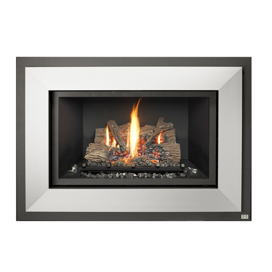
Face Details
WARNING: The face requires a 1/4" gap between the face
and facing (tile, drywall, etc.). This gap provides airflow to
allow the fireplace to operate correctly.
SIDE OF FIREPLACE
NOTE:
Allow an additional 1" gap below the face when using the switch box
(2" below the base of the fireplace - see the next page for switch box explanation.)
Page 1 of 8
Shadowbox Face (564) Installation Instructions
Satin 95400424
1/4"
1-1/4"
2-3/4"
NOTE:
The face requires 1" below the base of the fireplace (3/4" for the face, 1/4" for
1"
air ventilation). The fireplace must be raised a minimum 1" above the hearth
to accommodate this face.
17601627.docx - 5/20/13
Nickel 95400423
•
Control Panel Label
•
Double-Back Tape
•
Scotch-Brite™ Pad (for Nickel only)
•
(8) Screws (#8 x 3/8" Phillips) – multiple
locations
•
(5) Screws (#8 x 5/8" hex head)
45-1/4"
.
.
32 - 1/4"
© Travis Industries, Inc.
Advertisement

Related Manuals for Travis Industries 95400424


Summary of Contents for Travis Industries 95400424
- Page 1 Allow an additional 1" gap below the face when using the switch box (2" below the base of the fireplace - see the next page for switch box explanation.) Page 1 of 8 17601627.docx - 5/20/13 © Travis Industries, Inc.
-
Page 2: Switch Box Installation
Pull the knob off the accent light rheostat. Unscrew the rheostat nut to remove the rheostat from the control panel. Disconnect the two wires leading to this rheostat (see Figure 2). Figure 2 Page 2 of 8 17601627.docx - 11/1/12 © Travis Industries, Inc. - Page 3 (see Figure 4). If using an optional blower, connect the wires labeled FAN CONTROL on the Switch Box wiring harness to the blower wires on the fireplace. Figure 4 Page 3 of 8 17601627.docx - 11/1/12 © Travis Industries, Inc.
- Page 4 (if applicable). Connect the wiring to the components (see Figure 7). Route the wires through the wire hanger clips on the back side of the switch box. Figure 7 Page 4 of 8 17601627.docx - 11/1/12 © Travis Industries, Inc.
- Page 5 Make sure all wiring is properly routed and does not contact any hot or moving components. Replace the control panel and concealment cover to complete installation of the switch box. Page 5 of 8 17601627.docx - 11/1/12 © Travis Industries, Inc.
- Page 6 Special Instructions for Brushed Aluminum Make sure to handle the brushed aluminum with gloves to prevent staining. #8 x 5/8” Hex Head Screws Pre-Threading Holes Bottom Shield Figure 10 Figure 11 Page 6 of 8 17601627.docx - 11/1/12 © Travis Industries, Inc.
- Page 7 Special Instructions for Brushed Aluminum Make sure to handle the brushed aluminum with gloves to prevent staining. Figure 12 Figure 13 Page 7 of 8 17601627.docx - 11/1/12 © Travis Industries, Inc.
- Page 8 If using manual mode, attach the control label as shown in Figure 15, 9.25” away from the bottom right edge of the face. NOTE: If using a GreenSmart remote, the control label is not necessary. 9.25” - 564 SS, 564 DF, 564 HO Figure 15 Page 8 of 8 17601627.docx - 11/1/12 © Travis Industries, Inc.