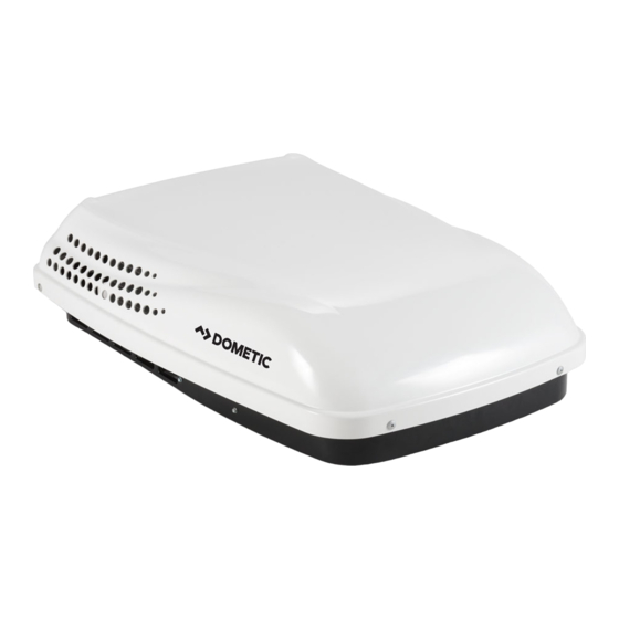
Dometic 640312 Series Installation And Operating Instructions Manual
Roof top unit
Hide thumbs
Also See for 640312 Series:
- Installation and operation manual (28 pages) ,
- Installation instructions manual (24 pages) ,
- Installation & operating instructions manual (15 pages)
Table of Contents
Advertisement
USA
SERVICE OFFICE
Dometic Corporation
1120 North Main Street
Elkhart, IN 46514
CANADA
Dometic Corporation
46 Zatonski, Unit 3
Brantford, Ontario
CANADA N3T 5L8
For Service Center &
Dealer Locations
Please Visit:
www.eDometic.com
INSTALLATION & OPERATING
INSTRUCTIONS
REVISION A
Form No. 3312501.012 08/16
(French 3312703.014_A)
©2016 Dometic Corporation
LaGrange, IN 46761
Description
Air Conditioner
Note: Installation requires a #2 Phillips screwdriver
with 9/32" maximum diameter x 1-1/4" minimum length.
This manual must be read and
understood before installation,
adjustment, service, or mainte-
nance is performed. This unit must
be installed by a qualified service
technician. Modification of this
product can be extremely hazard-
ous and could result in personal
injury or property damage.
Read these instructions carefully. These
instructions MUST stay with this product.
Roof Top Unit
Model
Use With Air Distribution Box
Model
640312
3310741.XXX
Integral Mechanical
640315
Lire et comprendre ce manuel avant de
procéder à l'installation, à des réglages,
de l'entretien ou des réparations.
L'installation de ce produit doit être
effectuée par un réparateur qualifié.
Toute modification de ce produit peut
être extrêmement dangereuse et
entraîner des blessures ou dommages
matériels.
640312.30X
640312C35X
640312.80X
640312.83X
640312C85X
640315.30X
RECORD THIS UNIT INFORMATION
FOR FUTURE REFERENCE:
Model Number
Serial Number
ADB Number
ADB Serial Number
Date Purchased
Control
Electric Heat
N/A
MODELS
640315C35X
640315.80X
640315.83X
640315.84X
640315C85X
Advertisement
Table of Contents

Summary of Contents for Dometic 640312 Series
- Page 1 640312.30X 640315C35X INSTALLATION & OPERATING 640312C35X 640315.80X 640312.80X 640315.83X INSTRUCTIONS 640312.83X 640315.84X 640312C85X 640315C85X 640315.30X REVISION A Form No. 3312501.012 08/16 (French 3312703.014_A) Read these instructions carefully. These ©2016 Dometic Corporation instructions MUST stay with this product. LaGrange, IN 46761...
-
Page 2: Important Safety Instructions
For a more permanent solution to a high heat gain, ac- in death or serious injury. cessories like Dometic outdoor patio and window awnings will reduce heat gain by removing the direct exposure to the sun. They also add a nice area to enjoy company dur- CAUTION, used with the safe- ing the cool of the evening. -
Page 3: Specifications
For wire length over 24 ft., consult the National Electric Code for proper sizing. ** Dometic Corporation gives GENERAL guidelines for generator requirements. These guidelines come from experiences people have had in actual applications. When sizing the generator, the total power usage of your recreational vehicle must be considered. -
Page 4: Installation Instructions
Center Line tion. Of Unit Front 2. Dometic Corporation will not be liable for any damages or injury incurred due to failure in fol- lowing these instructions. 3. Installation MUST comply with the National Elec- 4"... -
Page 5: Roof Preparation
C. Roof Preparation FIG. 3 1. Opening requirements - Before preparing the ceiling opening, read all of the following instruc- tions before beginning the installation. If an existing roof vent opening will not be used a 14-1/4" x 14-1/4" (±1/8") opening must be cut through the roof and ceiling of the RV. -
Page 6: Wiring Requirements
FIG. 4 Lift And Place D. Wiring Requirements 1. Route a copper, with ground, 120 VAC supply wire from the time delay fuse or circuit breaker FRONT box to the roof opening. The proper size wire can be determined from chart on page 3. Do Not Slide Note: If vent fan was removed, the existing wire may be used provided it is of proper size, location, and correctly... - Page 7 5. Base Pan Duct Adapter. FIG. 8 a. Remove the liner from the foam tape and posi- tion on the base so screw hole and air openings are aligned. See FIG. 7. Snap Cover FIG. 7 In Place Af- Front Discharge ter Wires Are Opening Place...
-
Page 8: Air Distribution Box Installation
• Evenly tighten the bolts to a torque G. Air Distribution Box Installation of 40 to 50 inch pounds. This will compress the roof gasket to ap- mportant: The inner walls of the ADB go inside the proximately 1/2". The bolts are self walls of the ceiling template during installation. -
Page 9: Operating Instructions
OPERATING INSTRUCTIONS FIG. 13 Auxiliary Screw Locations A. 3310741 Air Distribution Box With Me- chanical Controls 1. Selector Switch & Thermostat a. Model 3310741 ADB has a five position Se- lector Switch including "OFF". This controls fan speed and cooling modes. See FIG. 14. b. -
Page 10: Maintenance
MAINTENANCE SERVICE-UNIT DOES NOT OPERATE A. Air Filter If your unit fails to operate or operates improperly, check 1. Periodically (a minimum of every 2 weeks of op- the following before calling your service center. eration) slide out the return air filters located on the end of the air distribution box. -
Page 11: Unit Diagram
WIRING DIAGRAMS Unit Diagram Air Distribution Box Wiring Diagram BLU/BLK BLK/ORG ROTARY SWITCH GRN/YEL THERMOSTAT GRN/ 115V~ FIELD WIRING 60 HZ 1 FACTORY WIRING USE COPPER CONDUCTORS ONLY 3313033.000...


