Riello Gulliver RG1RK Installation, Use And Maintenance Instructions
Light oil burner
Hide thumbs
Also See for Gulliver RG1RK:
- Installation, use and maintenance instructions (52 pages) ,
- Installation, use and maintenance instructions (24 pages) ,
- Installation, use and maintenance instructions (17 pages)

Related Manuals for Riello Gulliver RG1RK


Summary of Contents for Riello Gulliver RG1RK
- Page 1 Installation, use and maintenance instructions Light oil burner One stage operation CODE MODEL TYPE 3736254 RG1RK 362 T1 2903259 (2) - 11/2011...
- Page 2 Declaration Declaration of conformity in accordance with ISO / IEC 17050-1 Manufacturer: RIELLO S.p.A. Address: Via Pilade Riello, 7 37045 Legnago (VR) Product: Light oil burner Model: RG1RK These products are in compliance with the following Technical Standards: EN 267...
-
Page 3: Table Of Contents
INDEX BURNER DESCRIPTION........... . . Burner equipment . -
Page 4: Burner Description
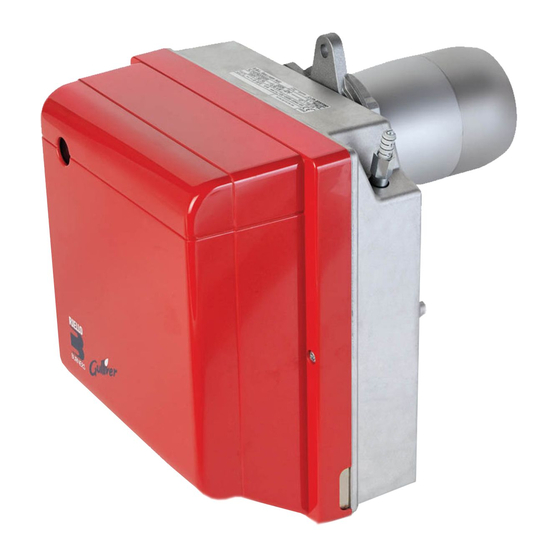
BURNER DESCRIPTION One stage light oil burner. The burner meets protection level of IP X0D (IP 40), EN 60529. The burner is approved for intermittent operation. Fig. 1 D7367 1 – Oil pump 6 – Nozzle holder assembly 2 –... -
Page 5: Technical Data
TECHNICAL DATA TECHNICAL DATA TYPE 362 T1 Output - Thermal power 5 kg/h – 60 kW Fuel - Light oil, viscosity 4 6 mm /s at 20 °C ± Electrical supply Single phase, 50Hz 230 V Motor Run current 0.85 A – 2750 rpm – 289 rad/s 4 F Capacitor Ignition transformer... -
Page 6: Installation
INSTALLATION THE BURNER MUST BE INSTALLED IN CONFORMITY WITH LEGISLATION AND LOCAL STANDARDS. WORKING POSITION The burner is designed to work only in the positions, 1 and 2. Installation 1 is preferable, as it is the only one that allows performing maintenance operations as described in this manual. Installations 2 allow working operations but not maintenance with hooking to the boiler. -
Page 7: Hydraulic Systems
HYDRAULIC SYSTEMS Fig. 4 WARNING: The burner is designed to accomodate the installation of light oil supply pipes on either side of the burner. It is necessary to install a filter on the fuel supply line. The pump is designed for use with a two-pipe system. In order to obtain one-pipe working, it is necessary to unscrew the return plug (2), remove the by-pass screw D5487... -
Page 8: Electrical Wiring
ELECTRICAL WIRING ATTENTION: Do not swap neutral and phase over, follow the diagram shown carefully and carry out a good earth connection. The section of the conductors must be at least 1mm². (Unless requested otherwise by local standards and legislation). ... -
Page 9: Burner Operation
BURNER OPERATION WARNING QUALIFIED PERSONNEL WITH THE RIGHT INSTRUMENTS MUST HANDLE THE BURNER'S FIRST START-UP COMBUSTION ADJUSTMENT In conformity with Efficiency Directive 92/42/EEC the application of the burner on the boiler, adjustment and testing must be carried out observing the instruction manual of the boiler, including verification of the CO and CO concentration in the flue gases, their temperatures and the average temperature of the water in the boiler. -
Page 10: Maintenance Position
MAINTENANCE POSITION Before performing maintenance on the burner, it is best to disconnect the system's power supply. ACCESSIBILITY TO THE NOZZLE, THE DIFFUSER DISC AND THE ELECTRODES IS MADE EASY IN 2 WAYS: Remove the burner from the boiler after having Remove thenozzle-holder assembly (7) after loosing the screw (8), unscrewing the nut (9), removed the fixing nuts to the flange. -
Page 11: Combustion Head Adjustment
COMBUSTION HEAD ADJUST- Fig. 12 MENT, (fig. 12) The adjustment of the combustion head varies de- pending on the burner output. Do the following to adjust it: Rotate the setting screw (12) clockwise or coun- terclockwise until the set-point marked on the regulating rod (13) is level with the outside plane of the nozzle-holder assembly (7). -
Page 12: Operating Programme
OPERATING PROGRAMME 4.9.1 NORMAL OPERATION WITH PREHEATING KEY TO LAY-OUT – Flame detector – Ignition transformer – Thermostat enabling start-up after pre- heating LED – Reset button LED indicating operating status MV – Fan motor PH – Oil heater TL – Limit thermostat V1 –... -
Page 13: Lockout Due To Firing Failure
4.9.2 LOCKOUT DUE TO FIRING FAILURE KEY TO LAY-OUT – Flame detector – Ignition transformer – Thermostat enabling start-up after pre- heating LED – Reset button LED indicating operating status MV – Fan motor PH – Oil heater Green+Yellow TL – Limit thermostat V1 –... -
Page 14: Lockout Types And Triggering Times In Case Of Burner Malfunction
COLOUR CODE OF CONTROL BOX RESET BUTTON LED Flashing Operating status LED colour codes speed Seconds Standby LED unlit Preheating Yellow Pre-purging Green Long pre-purging Green Transformer ignition Green + Yellow flashing Fast Regular flame Green + Yellow flashing Slow Post-purging Green + Yellow Recycle... -
Page 15: Additional Programmable Control Box Functions
4.10 ADDITIONAL PROGRAMMABLE CONTROL BOX FUNCTIONS 4.10.1 POST-PURGING FUNCTION (t6) Post-ventilation is a function that maintains air ventilation even after the burner is switched off. The burner switches off when the limit thermostat (TL) opens, cutting off the fuel supply to the valves. To use this function the reset button must be pressed when the limit thermostat is not switched over (burner switched off). -
Page 16: Maintenance
MAINTENANCE Disconnect the electric supply to the burner by switching off the main power switch and close the light oil shut-off valve before maintaining or checking the system. The burner requires scheduled maintenance that must be carried out by qualified personnel and in compliance with local legislation. -
Page 17: Faults / Solutions
SIGNAL PROBABLE CAUSE Loss of flame during operations: 7 pulses – poor burner regulation (insufficient gas); – oil valve faulty or dirty; – flame detector faulty or dirty. Check and monitor oil heater (if fitted): 8 pulses – heater or control thermostat faulty. ATTENTION To reset the control box after the diagnostics display, press the lockout-reset button. -
Page 18: Operating Irregularities
FAULT POSSIBLE CAUSES SOLUTION The ignition electrodes are wrongly Adjust them according to the positioned. instructions of this manual. Burner starts with an Set the air output according to the ignition delay. Air output is too high. instructions of this manual. Nozzle dirty or worn. -
Page 19: Warnings And Safety
WARNINGS AND SAFETY The dimension of the boiler’s combustion chamber must respond to specific values, in order to guarantee a combustion with the lowest polluting emissions rate. You are therefore advised to consult the Technical Assistance Department before choosing this type of burner for the combination with a boiler. - Page 20 RIELLO S.p.A. I-37045 Legnago (VR) Tel.: +39.0442.630111 http:// www.riello.it http:// www.rielloburners.com Subject to modifications...