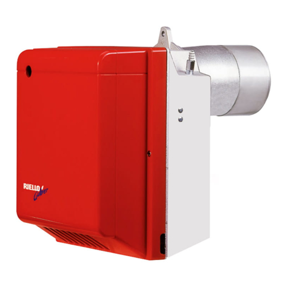
Riello Gulliver RG4D Installation, Use And Maintenance Instructions
Light oil burner, one stage operation
Hide thumbs
Also See for Gulliver RG4D:
- Installation, use and maintenance instructions (52 pages) ,
- Installation, use and maintenance instructions (40 pages) ,
- Installation, use and maintenance instructions (72 pages)
Table of Contents
Advertisement
Available languages
Available languages
Quick Links
Istruzioni per installazione, uso e manutenzione
Montage und Bedienungsanleitung
Manuel d'entretien
Installation, use and maintenance instructions
Installatie-, gebruiks- en onderhoudsvoorschriften
Bruciatore di gasolio
I
Öl-Gebläsebrenner
D
Brûleur fioul domestique
F
Light oil burner
GB
Stookoliebrander
NL
Funzionamento monostadio
Einstufiger Betrieb
Fonctionnement à 1 allure
One stage operation
Eentrapsbrander
CODICE
CODE
3739700
MODELLO - MODELL
MODELE - MODEL
RG4D
TIPO - TYP
TYPE
397T1
2901917 (11) - 10/2007
Advertisement
Chapters
Table of Contents

Related Manuals for Riello Gulliver RG4D


Summary of Contents for Riello Gulliver RG4D
- Page 1 Istruzioni per installazione, uso e manutenzione Montage und Bedienungsanleitung Manuel d’entretien Installation, use and maintenance instructions Installatie-, gebruiks- en onderhoudsvoorschriften Bruciatore di gasolio Öl-Gebläsebrenner Brûleur fioul domestique Light oil burner Stookoliebrander Funzionamento monostadio Einstufiger Betrieb Fonctionnement à 1 allure One stage operation Eentrapsbrander CODICE MODELLO - MODELL...
- Page 2 DICHIARAZIONE DI CONFORMITÀ A.R. 8/1/2004 – Belgio Produttore: RIELLO S.p.A. Via degli Alpini, 1 37045 LEGNAGO (VR) Italy Tel. ++39.0442630111 Fax ++39.044221980 Messa in circolazione da: RIELLO NV Ninovesteenweg 198 9320 Erembodegem Tel. (053) 769 030 Fax. (053) 789 440 e-mail.
-
Page 3: Table Of Contents
INDICE DESCRIZIONE DEL BRUCIATORE ..4.1 Regolazione della combustione..1.1 Materiale a corredo ....4.2 Ugelli consigliati ....4.3 Regolazione testa di combustione . -
Page 4: Dati Tecnici
DATI TECNICI DATI TECNICI TIPO 397 T1 ÷ ÷ Portata - Potenza termica 9 / 11 20 kg/h – 106 / 130 237 kW ÷ Combustibile Gasolio, viscosità 4 6 mm /s a 20°C ± Alimentazione elettrica Monofase, 230 V 50Hz Motore 2 A assorbiti –... -
Page 5: Installazione
INSTALLAZIONE FISSAGGIO ALLA CALDAIA Inserire sulla flangia (1) la vite e i due dadi, (vedi fig. 3). Allargare, se necessario, i fori dello schermo isolante (4), (vedi fig. 4). Fissare alla portina della caldaia (3) la flangia (1) mediante le viti (5) e (se necessario) i dadi (2) interponendo lo schermo isolante (4), (vedi fig. -
Page 6: Impianti Idraulici
IMPIANTI IDRAULICI ATTENZIONE Accertarsi, prima di mettere in funzione il bruciatore, che il tubo di ritorno del combustibile non abbia occlusioni. Una eccessiva contro- pressione provocherebbe la rottura dell’organo di tenuta della pompa. La pompa è predisposta per funzionamento bitubo. Per il funzionamento monotubo è... -
Page 7: Collegamenti Elettrici
COLLEGAMENTI ELETTRICI NOTE: Non scambiare il neutro con la fase, rispettare esattamente lo schema indicato ed eseguire un buon colle- gamento di terra. La sezione dei conduttori deve essere di min. 1 mm . (Salvo diverse indicazioni di norme e leggi locali). I collegamenti elettrici eseguiti dall’installatore devono rispettare le norme vigenti nel paese. -
Page 8: Funzionamento
FUNZIONAMENTO REGOLAZIONE DELLA COMBUSTIONE In conformità con la Direttiva Rendimento 92/42/CEE, l’applicazione del bruciatore alla caldaia, la regolazione e il collaudo, devono essere eseguiti nell’osservanza del manuale d’istruzione della caldaia stessa, compreso il controllo della concentrazione di CO e CO nei fumi, della loro temperatura e di quella media dell’acqua della caldaia. -
Page 9: Regolazione Testa Di Combustione
REGOLAZIONE TESTA DI COMBUSTIONE, (vedi fig. 12, pag. 6) Dipende dalla portata del bruciatore e si esegue ruotando in senso orario o antiorario la vite di regolazione (6) fino a che la tacca incisa sulla staffa di regolazione (7) coincide con il piano esterno del gruppo portaugello (1). –... -
Page 10: Programma Di Avviamento
PROGRAMMA DI AVVIAMENTO Normale Blocco per mancata accensione Termostato 1° stadio Termostato 2° stadio Motore Trasf. d’accensione Valvola 1° stadio Fiamma 1° stadio Valvola 2° stadio Fiamma 2° stadio Spia blocco ÷ D6040 Segnalato dalla spia sull’apparecchiatura di comando e controllo (4, fig. 1, pag. 1). MANUTENZIONE Il bruciatore richiede una manutenzione periodica, che deve essere eseguita da personale abilitato e in conformità... -
Page 11: Anomalie / Rimedi
ANOMALIE / RIMEDI Si elencano alcune cause e i possibili rimedi a una serie di anomalie che potrebbero verificarsi e portare ad un mancato o non regolare funzionamento del bruciatore. Un’anomalia, nel funzionamento nella maggior parte dei casi, porta alla accensione della segnalazione all’in- terno del pulsante di sblocco dell’apparecchiatura di comando e controllo (pos. -
Page 12: Avvertenze E Sicurezza
AVVERTENZE E SICUREZZA Al fine di garantire una combustione col minimo tasso di emissioni inquinanti, le dimensioni ed il tipo di ca- mera di combustione del generatore di calore, devono corrispondere a valori ben definiti. È pertanto consigliato consultare il Servizio Tecnico di Assistenza prima di scegliere questo tipo di brucia- tore per l’abbinamento con una caldaia. - Page 13 KONFORMITÄTSERKLÄRUNG K.E. 8.1.2004 - Belgium Hergestellt von: RIELLO S.p.A. Via degli Alpini, 1 37045 LEGNAGO (VR) Italy Tel. ++39.0442630111 Fax ++39.044221980 In den Verkehr gebracht durch: RIELLO NV Ninovesteenweg 198 9320 Erembodegem Tel. (053) 769 030 Fax. (053) 789 440 e-mail.
-
Page 14: Beschreibung Des Brenners
INHALT BESCHREIBUNG DES BRENNERS . . . 4.1 Einstellung der Brennerleistung..1.1 Mitgeliefertes Zubehör ....4.2 Empfohlene Düsen ....4.3 Brennkopfeinstellung. -
Page 15: Technische Merkmale
TECHNISCHE MERKMALE 2.1 TECHNISCHE DATEN 397 T1 ÷ ÷ Durchsatz - Feuerungswärmeleistung 9 / 11 20 kg/h – 106 / 130 237 kW ÷ Brennstoff Heizöl-EL, Viskosität 4 6 mm /s bei 20°C ± Stromversorgung Einphasig, 50Hz 230 V Motor Stromaufnahme 2 A –... -
Page 16: Installation
INSTALLATION 3.1 BRENNERMONTAGE Die Schraube und die beiden Muttern am Flansch (1) montieren, (siehe Abb. 3). Falls erforderlich, die Bohrungen der Isolierdichtung (4) erweitern, (siehe Abb. 4). Mit den Schrauben (5) und (falls erforderlich) den Muttern (2) den Flansch (1) an der Kesseltür (3) mit Isolierdichtung (4) montieren, (siehe Abb 2). -
Page 17: Ölversorgungsanlage
3.3 ÖLVERSORGUNGSANLAGE Abb. 8 WICHTIGER HINWEIS: Es muß sichergestellt werden, daß die Ölrücklauf-Leitung ohne Veren- gung und Verstopfung frei in den Tank zurückgeführt wird. Durch Druckerhöhung von mehr als 0,5 bar im Rücklauf wird die Ölpumpe undicht. Die Pumpe ist werksseitig für den Zweirohr-Betrieb eingerichtet. Wird ein Pumpen-Einrohrbetrieb für notwendig erachtet, so ist der Rücklauf- Schlauchleitungsstopfen (2) zu lösen und die By-Pass Schraube (3) zu entfernen. -
Page 18: Elektrisches Verdrahtungsschema
3.4 ELEKTRISCHES VERDRAHTUNGSSCHEMA ACHTUNG: Nullleiter nicht mit Phase austauschen; sich genau an das angegebene Schema halten und eine gute Er- dung ausführen. Der Leiterquerschnitt muss mindestens 1 mm2 sein. (Außer im Falle anderslautender Angaben durch Normen und örtliche Gesetze). Die vom Installateur ausgeführten elektrischen Verbindungen müssen den lokalen Bestimmungen entsprechen. (Siehe Seite 4). -
Page 19: Einstellung Der Brennerleistung
BETRIEB EINSTELLUNG DER BRENNERLEISTUNG In Konformität mit der Wirkungsgradrichtlinie 92/42/EWG müssen die Anbringung des Brenners am Heizkessel, die Einstellung und die Inbetriebnahme unter Beachtung der Betriebsanleitung der Heizkessels ausgeführt werden, einschließlich Kontrolle der Konzentration von CO und CO in den Abgasen, ihrer Temperatur und der mittlenen Kesseltemperatur. -
Page 20: Brennkopfeinstellung
4.3 BRENNKOPFEINSTELLUNG, (siehe Abb. 12, Seite 6) Sie ist vom Öldurchsatz abhängig und wird ausgeführt, indem man die Einstellschraube (6) im Uhrzeigersinn oder entgegen dem Uhrzeigersinn soweit dreht, bis die auf der Einstellspindel markierte Raste (7) mit der Kante am Düsenstock (1) übereinstimmt. In der Abbildung ist der Brennkopf auf einen Durchsatz von 3,50 GPH bei 15 bar eingestellt. -
Page 21: Betriebsablauf
4.6 BETRIEBSABLAUF Störabschaltung Normal wegen Nichtzündung 1. Stufe Thermostat 2. Stufe Thermostat Motor Zündtransformator 1. Stufe Ventil 1. Stufe Flamme 2. Stufe Ventil 2. Stufe Flamme Störlampe ÷ D6040 Wird durch die Kontrollampe am Steuer- und Überwachungsgerät signalisiert (4, Abb. 1, S. 1). WARTUNG Der Brenner muß... -
Page 22: Störungen / Abhilfe
STÖRUNGEN / ABHILFE Nachfolgend finden Sie einige denkbare Ursachen und Abhilfemöglichkeiten für Störungen, die den Betrieb des Brenners beeinflussen oder einen nicht ordnungsgemäßen Betrieb des Brenners verursachen könnten. In den meisten Fällen führt eine Störung zum Aufleuchten der Kontrolleuchte in der Entstörtaste des Steu- ergeräts (4, Abb. -
Page 23: Hinweise Und Sicherheit
HINWEISE UND SICHERHEIT Um bestmögliche Verbrennungs-Ergebnisse sowie niedrige Emissionswerte zu erzielen, muß die Brenn- kammer-Geometrie des Heizkessels für den Brenner geeignet sein. Deshalb ist es notwendig, vor Einsatz des Brenners Informationen bei einzuholen, um ein einwandfreies Funktionieren des Brenners zu gewährleisten. Dieser Brenner darf nur für den Einsatzzweck verwendet werden, für den er hergestellt wurde. - Page 24 DÉCLARATION DE CONFORMITÉ A.R. 8/1/2004 – Belgium Fabricant: RIELLO S.p.A. Via degli Alpini, 1 37045 LEGNAGO (VR) Italy Tel. ++39.0442630111 Fax ++39.044221980 Mise en circulation par: RIELLO NV Ninovesteenweg 198 9320 Erembodegem Tel. (053) 769 030 Fax. (053) 789 440 e-mail.
-
Page 25: S7242
SOMMAIRE DESCRIPTION DU BRULEUR ..4.1 Réglage de la combustion ... . 1.1 Matériel fourni ....4.2 Gicleurs conseillés . -
Page 26: Donnees Techniques
DONNEES TECHNIQUES 2.1 DONNEES TECHNIQUES TYPE 397 T1 ÷ ÷ Débit - Puissance thermique 9 / 11 20 kg/h – 106 / 130 237 kW ÷ Combustible Fioul domestique, viscosité 4 6 mm /s à 20°C ± Alimentation électrique Monophasée, 50Hz 230 V Moteur 2 A absorbés... -
Page 27: Installation
INSTALLATION 3.1 FIXATION A LA CHAUDIERE Insérer sur la bride (1) la vis et deux écrous, (voir fig. 3). Elargir, si nécessaire, les trous dans le joint isolant (4), (voir fig. 4). Fixer sur la plaque de la chaudière (3) la bride (1) par l’intermédiaire des vis (5) et (si nécessaire) des écrous (2) en interposant le joint isolant (4), (voir fig. -
Page 28: Installation Hydraulique
3.3 INSTALLATION HYDRAULIQUE Fig. 8 IMPORTANT: Avant de mettre en fonction le brûleur il faut s’assurer que le tube de retour du combustible ne soit pas obstrué. Une contre-pression exces- sive provoquerait la rupture de l’organe d’étanchéité de la pompe. La pompe est prévue pour un fonctionnement en bitube. -
Page 29: Raccordements Électriques
3.4 RACCORDEMENTS ELECTRIQUES ATTENTION: Ne pas inverser le neutre et la phase, respecter exactement le schéma indiqué et brancher correctement à la terre. La section des conducteurs doit être d'au moins 1 mm². (Sauf des indications différentes prévues par les normes et les lois locales). -
Page 30: Fonctionnement
FONCTIONNEMENT 4.1 REGLAGE DE LA COMBUSTION Conformément à la Directive rendement 92/42/CEE, suivre les indications du manuel de la chaudière pour monter le brûleur, effectuer le réglage et l’essai, contrôler la concentration de CO et CO , dans les fumées, leur température et celle moyenne de l’eau de la chaudière. -
Page 31: Réglage Tête De Combustion
4.3 REGLAGE TETE DE COMBUSTION, (voir fig. 12, page 6) Est en fonction du débit du brûleur et on l’obtient en tournant la vis (6) jusqu’à ce que l’index sur la tige de régla- ge (7) concorde avec le plan (1) sur le groupe porte-gicleur. Dans le dessin la tête est réglée pour un débit de 3,50 GPH à... -
Page 32: Programme De Mise En Marche
4.6 PROGRAMME DE MISE EN MARCHE Mise en sécurité Normal due à non allumage Therm. 1 ère allure Therm. 2 ème allure Moteur Transf. d’allumage 1 ère allure Vanne Flamme 1 ère allure 2 ème allure Vanne Flamme 2 ème allure Mise en sécurité... -
Page 33: Pannes / Remedes
PANNES / REMEDES La liste ci-dessous donne un certain nombre de causes d’anomalies et leurs remèdes. Problèmes qui se traduisent par un fonctionnement anormal du brûleur. Un défaut, dans la grande majorité des cas, se traduit par l'allumage du signal sur le bouton de réarme- ment manuel de la boîte de commande et de contrôle (4, fig. -
Page 34: Conseils Et Sécurité
CONSEILS ET SÉCURITÉ Afin de garantir une combustion avec le taux minimum des émissions polluantes, les dimensions et le type de chambre de combustion du générateur doivent correspondre à des valeurs bien déterminées. Il est donc conseillé de consulter le Service Technique avant de choisir ce type de brûleur pour l’équipement d’une chaudière. - Page 35 DECLARATION OF CONFORMITY Royal Decree (A.R.) 8/1/2004 - Belgium Producer: RIELLO S.p.A. Via degli Alpini, 1 37045 LEGNAGO (VR) Italy Tel. ++39.0442630111 Fax ++39.044221980 Distributed by: RIELLO NV Ninovesteenweg 198 9320 Erembodegem Tel. (053) 769 030 Fax. (053) 789 440 e-mail.
- Page 36 INDEX BURNER DESCRIPTION ... . 4.1 Combustion adjustment....1.1 Burner equipment ....4.2 Recommended nozzles .
- Page 37 TECHNICAL DATA 2.1 TECHNICAL DATA TYPE 397 T1 Output - Thermal power 9 / 11 – 20 kg/h 106 / 130 – 237 kW Fuel Light oil, viscosity 4 – 6 mm /s at 20 °C ± Electrical supply Single phase, 50Hz 230 V Motor Run current 2 A - 2730 rpm...
- Page 38 INSTALLATION 3.1 BOILER FIXING Put on the flange (1) the screw and two nuts, (see fig. 3). Widen, if necessary, the insulating gasket holes (4), (see fig. 4). Fix the flange (1) to the boiler door (3) using screws (5) and (if necessary) the nuts (2) interposing the insulating gasket (4), (see fig.
- Page 39 3.3 HYDRAULIC SYSTEMS Fig. 8 WARNING: Before starting the burner make sure that the return pipe-line is not clogged. An excessive back pressure would cause the damage of the pump seal. The pump is designed to allow working with two pipes. In order to obtain one pipe working it is necessary to unscrew the return plug (2), remove the by-pass screw (3) and then screw again the plug (2), (see fig.
- Page 40 3.4 ELECTRICAL WIRING ATTENTION: Do not swap neutral and phase over, follow the diagram shown carefully and carry out a good earth con- nection. The section of the conductors must be at least 1mm². (Unless requested otherwise by local standards and legislation). The electrical wiring carried out by the installer must be in compliance with the rules in force in the country.
- Page 41 WORKING 4.1 COMBUSTION ADJUSTMENT In conformity with Efficiency Directive 92/42/EEC the application of the burner on the boiler, adjustment and testing must be carried out observing the instruction manual of the boiler, including verification of the CO and CO concentration in the flue gases, their temperatures and the average temperature of the water in the boiler. To suit the required appliance output, choose the proper nozzle and adjust the pump pressure, the setting of the combustion head, and the air damper opening in accordance with the following schedule.
- Page 42 4.3 COMBUSTION HEAD SETTING, (see fig. 12, page 6) It depends on the output of the burner and is carried out by rotating clockwise or counterclockwise the set- ting screw (6) until the set-point marked on the regulating rod (7) is level with the outside plane of the nozzle-holder assembly (1).
- Page 43 4.6 BURNER START-UP CYCLE Normal Lock-out due to failure to light 1 st stage thermostat 2 nd stage thermostat Motor Ignition transformer 1 st stage valve 1 st stage flame 2 nd stage valve 2 nd stage flame Lock-out lamp 3 –...
- Page 44 FAULTS / SOLUTIONS Here below you can find some causes and the possible solutions for problems that could cause a failure to start or a bad working of the burner. A fault usually makes the lock-out lamp light which is situated inside the reset button of the control box (4, fig.
- Page 45 SAFETY WARNINGS The dimension of the boiler’s combustion chamber must respond to specific values, in order to guarantee a combustion with the lowest polluting emissions rate. The Technical Service Personnel will be glad to give you all the imformation for a correct matching of this burner to the boiler.
- Page 46 VERKLARING VAN OVEREENSTEMMING K.B. 8/1/2004 – Belgium Fabrikant: RIELLO S.p.A. Via degli Alpini, 1 37045 LEGNAGO (VR) Italy Tel. ++39.0442630111 Fax ++39.044221980 Op de markt gebracht door: RIELLO NV Ninovesteenweg 198 9320 Erembodegem Tel. (053) 769 030 Fax. (053) 789 440 e-mail.
- Page 47 INHOUD BESCHRIJVING BRANDER ..4.1 Regeling verbranding ....1.1 Geleverd materiaal....4.2 Aangewezen verstuivers .
-
Page 48: Technische Gegevens
TECHNISCHE GEGEVENS 2.1 TECHNISCHE GEGEVENS TYPE 397 T1 ÷ ÷ Oliedebiet - Thermisch vermogen 9 / 11 20 kg/h – 106 / 130 237 kW ÷ Brandstof Stookolie, viscositeit 4 6 mm /s bij 20 °C ± Elektrische voeding Monofasig, 50Hz 230 V Motor Opgenomen stroom 2 A –... -
Page 49: Installatie
INSTALLATIE 3.1 BEVESTIGING OP DE KETEL Schroef en twee moeren in de flens (1) aanbrengen, (zie fig. 3). Indien nodig, de gaten in de flensdichting (4) vergroten, (zie fig. 4). Bevestig de flens (1) op de ketelplaat (3) met behulp van de schroeven (5) en (indien nodig) de moeren (2) en voeg de flensdichting (4) ertussen, (zie fig. -
Page 50: Hydraulische Installatie
3.3 HYDRAULISCHE INSTALLATIE Fig. 8 OPGELET: Alvorens de brander op te starten, controleer of de terugloopleiding niet verstopt is. Daardoor zou immers de dichting van de pomp beschadigd kunnen worden. De pomp is voorzien voor een installatie met twee leidingen. Draai bij één leiding de moer van de terugloopleiding (2) los, verwijder de by-pass schroef (3) en draai de dop (2) opnieuw aan, (zie fig. -
Page 51: Elektrische Aansluitingen
3.4 ELEKTRISCHE AANSLUITINGEN OPGELET: Verwissel de nulleider niet met de fase, volg het weergegeven schema nauwkeurig en zorg voor een goede aardaansluiting. De doorsnede van de geleiders moet minstens 1 mm . (Mits anders voorgeschreven door plaatselijke nor- men en wetten). De elektrische aansluitingen die de installateur uitvoert, moeten voldoen aan de in het land van kracht zijnde reglementering. -
Page 52: Werking
WERKING 4.1 REGELING VERBRANDING Conform de Richtlijn Rendement 92/42/EEG, moeten de montage van de brander op de ketel, de regeling en de testen worden uitgevoerd volgens de handleiding van de ketel. Hieronder valt ook de controle van de CO en CO in de rookgassen, de temperatuur van de rookgassen en de gemiddelde temperatuur van het water van de ketel. -
Page 53: Afstelling Branderkop
4.3 AFSTELLING BRANDERKOP, (zie fig. 12, blz. 6) De branderkop wordt geregeld in functie van het branderdebiet door te draaien aan de schroef (6) tot het merk- teken op de regelstang (7) overeenstemt met het plan (1) van de verstuiverhoudergroep. Op de tekening hiernaast is de branderkop afgesteld voor een debiet van 3,50 GPH bij 15 bar. -
Page 54: Startprogramma
4.6 STARTPROGRAMMA In veiligheid (vergrendeling) Normaal bij gebrek aan ontsteking Therm. 1 ste vlamgang Therm. 2 de vlamgang Motor Ontstekingstransfo Klep 1 ste vlamgang Vlam 1 ste vlamgang Klep 2 de vlamgang Vlam 2d e vlamgang Vergrendeling ÷ D6040 Aangeduid door de LED (controlelamp) op de bedienings- en controledoos (4, fig. 1, blz. 1). ONDERHOUD De brander dient regelmatig aan een onderhoud door vaklui te worden onderworpen. -
Page 55: Defecten / Oplossingen
DEFECTEN / OPLOSSINGEN Hieronder vindt u een lijst met mogelijke defecten en oplossingen. Alle problemen geven aanleiding tot een abnormale werking van de brander. In de meeste gevallen gaat bij een probleem het lampje branden van de manuele herbewapeningsknop van de controle- en bedieningsdoos (4, fig. -
Page 56: Waarschuwingen En Veiligheid
WAARSCHUWINGEN EN VEILIGHEID Voor een verbranding met zo weinig mogelijk milieuverontreinigende emissies, moeten de afmetingen en het type verbrandingskamer van de ketel, overeenkomen met bepaalde waarden. Daarom is het raadzaam de Technische Servicedienst te raadplegen alvorens dit type brander te kiezen voor de combinatie met een ketel. Het vakbekwaam personeel is het personeel dat aan de technische professionele vereisten voldoet die voorgeschreven worden door de wet van 5 maart 1990 nr.