Table of Contents
Advertisement
For more information regarding bed rail safety, refer to the Bed Rail
Entrapment Risk Notification Guide at www.invacare.com.
This manual MUST be given to the user of the product.
BEFORE using this product, read this manual and save for future reference.If you are unable to
understand the warnings, cautions or instructions, contact a healthcare professional, dealer or
technical personnel before attempting to use this equipment
®
Invacare
G5510 Bed
Full Electric Bed
User Manual
IMPORTANT SAFETY INSTRUCTIONS
SAVE THESE INSTRUCTIONS
EN
Advertisement
Table of Contents
Troubleshooting

Related Manuals for Invacare G5510


Summary of Contents for Invacare G5510
- Page 1 SAVE THESE INSTRUCTIONS For more information regarding bed rail safety, refer to the Bed Rail Entrapment Risk Notification Guide at www.invacare.com. This manual MUST be given to the user of the product. BEFORE using this product, read this manual and save for future reference.If you are unable to...
- Page 2 © 2016 Invacare Corporation. All rights reserved. Republication, duplication or modification in whole or in part is prohibited without prior written permission from Invacare. Trademarks are identified by ™ and ®. All trademarks are owned by or licensed to Invacare Corporation or its subsidiaries unless otherwise noted.
-
Page 3: Table Of Contents
Operating the Bed ............................................... 36 Operating the Locking Function on the Locking Caster ................................38 Electrical Connections ............................................38 Installing/Removing Pendant and/or Port Cover ..................................39 Using the Emergency Crank..........................................41 Optional Bed Rails ............................................... 42 ® Part No 1180159 Invacare G5510 Bed... - Page 4 Installing/Removing Mattress Keepers......................................55 Connect Power Supply ............................................56 Storing the Bed..............................................57 TROUBLESHOOTING/MAINTENANCE - USER/DEALER Troubleshooting Electrical..........................................59 Troubleshooting Mechanical ..........................................61 MAINTENANCE AND CLEANING Maintenance Checklist ............................................63 Cleaning the Beds ..............................................64 ® Invacare G5510 Bed Part No 1180159...
-
Page 5: General
Caution indicates a potentially hazardous situation which, if not avoided, may result in property damage or minor injury or both. IMPORTANT! Indicates a hazardous situation that could result in damage to property if it is not avoided. Gives useful tips, recommendations and information for efficient, trouble-free use. ® Part No 1180159 Invacare G5510 Bed... -
Page 6: Symbols Used On Bed
Mark for US. A product Prohibition Symbol (Australian For Indoor Use bearing the ETL Listed (ISO 7010 - P001) EMC) Only Mark is determined to have met the minimum requirements of prescribed product safety standards. ® Invacare G5510 Bed Part No 1180159... -
Page 7: Symbols Used On Packaging
ISO 7000 - 0621 ISO 7000 - 0626 ISO 7000 - 2403 ISO 7000 - 0632 ISO 7000 - 2620 FRAGILE KEEP DRY DO NOT STACK OVER PERMITTED PERMITTED 2 HIGH TEMPERATURE HUMIDITY AREA RANGE ® Part No 1180159 Invacare G5510 Bed... -
Page 8: Limited Warranty
Invacare warrants the mechanical and electrical components of this product when purchased new and unused to be free from defects in materials and workmanship for a period of two years from date of purchase from Invacare or a dealer, with a copy of the seller’s invoice required for coverage under this warranty. -
Page 9: Overview
Close cover when not in use. Otherwise, personal injury may occur. Not Shown: P/N 1180192 Rev B p/n 1193317 Rev A p/n 1180137 Rev D p/n 1180192 Rev B Serial Label with UDI ® Part No 1180159 Invacare G5510 Bed... - Page 10 P/N 1171789 Rev D * This label is also located on the p/n 1171789 Rev D emergency crank. Labels shown for location and notice. Labels may change without notice. Contact your service provider or Invacare if label is missing or unreadable. ® Invacare...
-
Page 11: Specifications
32.25 ± 2 inches. Under Normal Use, the bed should operate in a height range of 15.25 ± 2 to 23.00 ± 2 inches. Recommended Atmospheric Pressure..............700 hpa to 1060 hpa ® Part No 1180159 Invacare G5510 Bed... - Page 12 Product Description The G5510 bed is a steel framed medical bed that allows for deck height adjustability and mattress deck articulation through the use of electronic actuators. The G5510 bed is for assisting in diagnosis, monitoring, prevention, treatment, alleviation of disease, or compensation for an injury or disability in an indoor environment.
-
Page 13: Accessories And Accessory Weight
The 6628, 6628-TSS, G6629, 6629, G6630, 6630, and 6632 bed rails are not approved for use with the G-series bed. The 5143IVC and 5143A bed extenders are not approved for use with the G-series bed. ® Part No 1180159 Invacare G5510 Bed... -
Page 14: Optional Touch-Up Paint
2 OVERVIEW The accessories in this table have not been tested to the international bed standard IEC 60601-2-52. They have been tested to comply with FDA Entrapment Guidelines when used with the G5510 bed and rails. DESCRIPTION MODEL NUMBER WEIGHT... -
Page 15: Safety
3 SAFETY 3 Safety General Guidelines The Invacare G5510 Bed has been engineered to provide reliable operation. The bed has been thoroughly tested and inspected prior to shipment. DANGER! Risk of Death, Injury or Death Bed accessories designed by other manufacturers have NOT been tested by Invacare. Use of NON-Invacare bed accessories may result in injury or death. - Page 16 - Check ALL product components and carton for damage, and test components before use. DO NOT use product if components are damaged or if product is not working properly. Contact a qualified technician or Invacare for repair. Conditions such as restlessness, mental deterioration and dementia or seizure disorders (uncontrolled body movement), sleeping problems, and incontinence can significantly impact a patient's risk of entrapment.
- Page 17 Follow local governing ordinances and recycling plans regarding disposal of the device or components normally used in operation. The device does not generate waste or residue in operation. Any accessories not part of the device MUST be handled in accordance with the individual product marking for disposal. ® Part No 1180159 Invacare G5510 Bed...
- Page 18 Replacement parts for a double-insulated product must be identical to the parts they replace. A double-insulated product is marked with the words “DOUBLE INSULATION” or “DOUBLE INSULATED”. The symbol ( ) is also able to be marked on the product. ® Invacare G5510 Bed Part No 1180159...
- Page 19 To avoid product damage: - DO NOT open assemblies such as the motors, pendant, junction boxes or gear boxes. No user serviceable parts are inside. Contact dealer or Invacare for repair/replacement. -Ensure gear box cover and all other assemblies are closed.
- Page 20 Risk of Death, Injury, or Damage To avoid electrical damage, product damage, shock and/or personal injury: - Keep all product components and accessories a minimum of 12 inches away from hot or heated surfaces. ® Invacare G5510 Bed Part No 1180159...
- Page 21 - Check ALL product components and carton for damage, and test components before use. DO NOT use product if components are damaged or if product is not working properly. Contact a qualified technician or Invacare for repair. -Before operating the bed, detach the power supply from the slat located under the bed. Keeping the power supply attached to the slat may cause overheating resulting in the bed malfunctioning.
- Page 22 - If liquid is spilled in or around the product, unplug before cleaning. Clean up the spill and allow the product or the area around the product to dry thoroughly before using the controls again. - If the product is not working properly, contact a qualified technician or Invacare for repair. DANGER!
- Page 23 - DO NOT move product with locking casters in LOCKED position. The emergency crank will turn when motor is on and could cause personal injury or damage to the bed. - ALWAYS remove emergency crank(s) before performing electronic functions. ® Part No 1180159 Invacare G5510 Bed...
- Page 24 - After the product has been assembled and before use, always test to make sure that all sections of the bed are properly and securely in place. If any problems arise during the test, recheck all electrical connections and mechanical hook ups and then retest. If the product is not working properly, contact a qualified technician or Invacare for repair. ®...
- Page 25 This will allow the protection function time to reset and restore bed function. Depending on the severity of the initial overheating, this could take up to 30 minutes. Pendant is constructed of latex-free materials. ® Part No 1180159 Invacare G5510 Bed...
- Page 26 - DO NOT open assemblies such as the motors, pendant, power supply or gear boxes. No user serviceable parts are inside. Contact dealer or Invacare for repair/replacement. - To avoid product damage, all electric cable connections MUST be aligned properly. Align locking levers with locking tabs for proper connection.
- Page 27 Risk of Death, Injury or Damage To avoid entrapment, product damage, and/or personal injury: -Invacare recommends that the mattress be centered on the bed frame. Otherwise, individuals may become trapped between the bed rail and the bed frame. -ALWAYS test to make sure that the side rails are properly and securely in place before using the bed. Otherwise, injury or damage may occur.
- Page 28 To avoid entrapment, product damage and/or personal injury: - When used with an Invacare bed, the bed rails DO NOT fall under any weight limitations. Bed rails can be deformed or broken if excessive side pressure is exerted on the bed rails. These bed rails are used for the purpose of preventing an individual from inadvertently rolling out of bed.
- Page 29 - Body weight should be evenly distributed over the surface of the bed. DO NOT lay, sit or lean in such a way that your entire body weight is placed only on raised head or foot sections of the bed. This includes when repositioning or transferring in or out of bed. ® Part No 1180159 Invacare G5510 Bed...
- Page 30 3 SAFETY Using Lifts with the G5510 Bed WARNING! Risk of Injury or Damage To avoid injury or damage from crush hazard: - Caregivers MUST be aware of the bed-floor clearance when using lifts or any other device that assists the bed user that enters between the lowest component of the bed and the floor.
-
Page 31: Emc Information
- This bed should not be used adjacent to or stacked with other equipment. If adjacent or stacked use with other equipment is necessary, this bed should be observed to verify normal operation in the configuration in which it will be used. ® Part No 1180159 Invacare G5510 Bed... - Page 32 NOTE 1: At 80 MHz and 800 MHz, the separation distance for the higher frequency range applies. NOTE 2: These guidelines may not apply in all situations. Electromagnetic propagation is affected by absorption and reflection from structures, objects and people. ® Invacare G5510 Bed Part No 1180159...
-
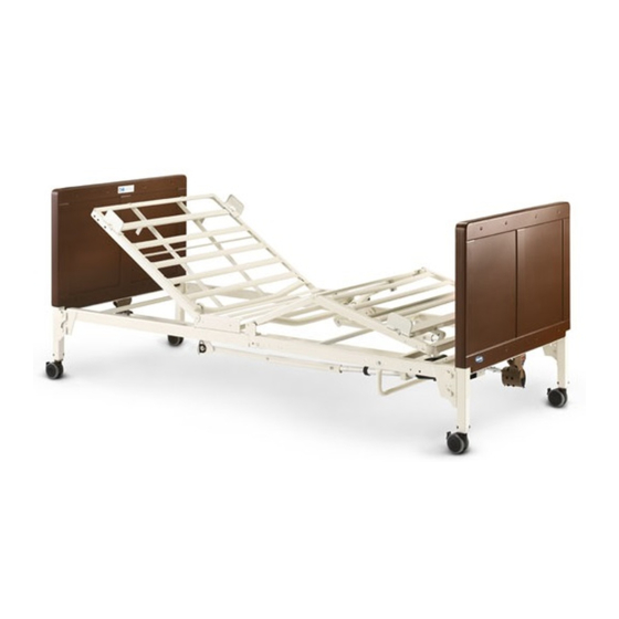
Page 33: Operation
Bed Operation and Component Overview Bed End Head Section Slat Bed End Locking Caster Bed Frame Foot Section Refer to Operating the Bed on page 36 Refer to Using the Emergency Crank on page 41 ® Part No 1180159 Invacare G5510 Bed... - Page 34 To avoid pinching, crush and collapse hazards from bed deck contact with objects under the bed: - DO NOT place any objects or let any individual underneath the bed or in between the raised bed frame components at anytime. ® Invacare G5510 Bed Part No 1180159...
-
Page 35: Operation Verification
This bed uses a six function pendant for all bed operations. This bed is equipped with an emergency crank to allow operation in the event of a power outage. Keep power supply as close to the electrical outlet as possible. ® Part No 1180159 Invacare G5510 Bed... -
Page 36: Operating The Bed
To raise the head of the bed, press the "Head Up" button; To lower the head of the bed, press the "Head Down" button. • To raise the foot of the bed, press the "Foot Up" button; To lower the foot of the bed, press the "Foot Down" button. ® Invacare G5510 Bed Part No 1180159... - Page 37 5 OPERATION Foot Up Button Head Up Button Foot Down Head Down Button Button Bed Up Head Section Button Bed Down Button Foot Section FIGURE 1 Operating the Bed ® Part No 1180159 Invacare G5510 Bed...
-
Page 38: Operating The Locking Function On The Locking Caster
Pendant/Port Pendant Cover Connection Connector Port Cover Flat Edge of Pendant Pendant Flat Edge of Connector Connector Flat Edge Port Cover FIGURE 3 Electrical Connections ® Invacare G5510 Bed Part No 1180159... -
Page 39: Installing/Removing Pendant And/Or Port Cover
Lower connector cap to lock the connection in place (Detail “F). Removing Port Cover To remove the port cover, lift the port cover cap (Detail “E) and remove the port cover from the bus cable port. ® Part No 1180159 Invacare G5510 Bed... - Page 40 Connector Cap Connector Cap Pendant Cable Cap Connector Cap Pendant Cable Bus Cable Port Connection MUST be Connection MUST be Bus Cable Port Port Cover tight tight FIGURE 4 Installing/Removing Pendant and/or Port Cover ® Invacare G5510 Bed Part No 1180159...
-
Page 41: Using The Emergency Crank
Turn clockwise to raise. Turn counterclockwise to lower. Emergency Crank Foot To Raise/Lower the Shaft of Head Actuator To Raise/Lower the Foot Section to Raise/Lower the Entire Bed Head Section FIGURE 5 Using the Emergency Crank ® Part No 1180159 Invacare G5510 Bed... -
Page 42: Optional Bed Rails
- Visit the FDA website at http://www.fda.gov to learn about the risks of entrapment. Review “A Guide to Bed Safety”, published by the Hospital Bed Safety Workgroup. Use the link located under each bed rail product entry to access this bed’s safety guide. ® Invacare G5510 Bed Part No 1180159... -
Page 43: Dealer Section - Packaging, Handling, And Set-Up
6 Dealer Section - Packaging, Handling, and Set-Up WARNING! Risk of Injury or Damage The procedures in this section MUST be performed by a qualified technician. Any modifications to the G5510 bed are strictly prohibited. Unpacking and Handling • Four Locking Casters. - Page 44 Head Section carton includes: One Head End Section. Any part of the head section may be gripped for handling. Shipping Carton Foot End Section Insert Head End Section Shipping Carton Insert Inserts Insert Pendant Cable Power Supply Insert FIGURE 2 Unpacking Foot and Head Sections ® Invacare G5510 Bed Part No 1180159...
-
Page 45: Inspecting
Inspecting DANGER! Risk of Injury or Damage To avoid injury or damage, inspect the following and contact a qualified technician or Invacare if any of the following issues are present: - Pendant covering is cracked or damaged. - Power cord or plug have cuts or damage. - Page 46 Hook the bottom head section center mounting latch to the bottom foot section center mounting rivet (FIGURE 4). Hook the top head section center mounting latch to the top foot section center mounting rivet (FIGURE 4). ® Invacare G5510 Bed Part No 1180159...
- Page 47 Connect the pull tube end assembly to the lift arm of the head section as follows (Detail "B"): Insert the clevis pin into the lift arm slot. Replace the grommet/washer. Secure with hitch pin. ® Part No 1180159 Invacare G5510 Bed...
- Page 48 Hitch Pin Head Section Pull Tube Grommet/Washer Outer Pull Tube Adjusting Hole Inner Pull Tube DETAIL “B” Lift-Arm Slot Clevis Pin Nylon Washer FIGURE 5 Adjusting and Reconnecting the Head Section Pull Tube ® Invacare G5510 Bed Part No 1180159...
-
Page 49: Assembling The Bed Ends
Grasp the head section, by the side, and raise it until the rivets on the corner plates of the section are high enough to place into the corner locks on the bed end (Detail “A”). ® Part No 1180159 Invacare G5510 Bed... - Page 50 While holding the bed end at the head of the bed, lift up on the head section and disengage the rivets out of the corner locks (Detail “A”). DETAIL “A” DETAIL “B” Bed End Bed End Foot Section Head Section Rivets Rivets Corner Locks Corner Locks FIGURE 7 Installing/Removing the Bed Ends ® Invacare G5510 Bed Part No 1180159...
- Page 51 Push in on the spring loaded end of the drive shaft and attach to the foot end of the bed as follows: • Attach drive shaft to the Hi/Lo motor output shaft facing head end of bed. ® Part No 1180159 Invacare G5510 Bed...
- Page 52 Release the Hi/Lo motor output shaft spring-loaded coupler by pushing in against the Hi/Lo motor output shaft spring-loaded coupler and turning clockwise. The coupling will release and engage the foot end top gear box output shaft cross pins. Ensure that all components are securely installed. ® Invacare G5510 Bed Part No 1180159...
- Page 53 UNLOCKED POSITION INPUT SIDE Hi/Lo Motor Output Shaft Gear Drive Drive Shaft Cover Hi/Lo Motor Shaft Output Shaft Input Drive Shaft Spring-Loaded (Covered) Hi/Lo Motor Coupler Shaft FIGURE 9 Assembling the Drive Shaft ® Part No 1180159 Invacare G5510 Bed...
-
Page 54: Electrical Connections
Ensure that all cable plugs are connected securely. Make sure all cables are routed properly. If damage is found, contact an Invacare Customer Service Representative to report the damaged items and request appropriate replacement parts or products. Make all the electrical connections. Refer to Electrical Connections on page 54. -
Page 55: Installing/Removing Mattress Keepers
Slide mattress keeper back until tab locks onto side rail as shown in Detail “C”. Removing Grasp mattress keeper and lift tab up to release from side rail (Detail “B”). Slide mattress keeper off of end slat (Detail “B”). ® Part No 1180159 Invacare G5510 Bed... -
Page 56: Connect Power Supply
Mattress Keeper End Slat End Slat FIGURE 11 Installing/Removing Mattress Keepers 6.7 Connect Power Supply Plug power supply into bus cable port marked power. Power Supply Bus Cable FIGURE 12 Connect Power Supply ® Invacare G5510 Bed Part No 1180159... -
Page 57: Storing The Bed
See Detail “B” in FIGURE 13. Coil up pendant cable and power supply cable and secure with hook and loop provided to the underside of the slat located above the support brace bed. ® Part No 1180159 Invacare G5510 Bed... - Page 58 6 DEALER SECTION - PACKAGING, HANDLING, AND SET-UP DETAIL “A” DETAIL “B” Power Supply Cable Power Supply Preferable location to secure power supply is this slat above the support brace Pendant Cable Pendant Support Brace FIGURE 13 Storing the Bed ® Invacare G5510 Bed Part No 1180159...
-
Page 59: Troubleshooting/Maintenance - User/Dealer
Refer to Assembling the Drive repair/replacement of cables Shaft on page 51. and/or motors. • Ensure cables are not entangled/pinched. • Call Invacare for instructions to repair/replacement of cables and/or motors. • Household fuse or breaker • Check household fuse/breaker blown. - Page 60 USER SOLUTIONS DEALER SOLUTIONS • Bed section does not move. • Broken connector cap. • Call dealer. • Call Invacare for instructions to replace connector cap. • Motors are not functioning. • Call dealer. • Check to make sure nothing is blocking actuator.
-
Page 61: Troubleshooting Mechanical
USER SOLUTIONS DEALER SOLUTIONS • Bed is producing unusual sounds, • Electrical Component Error. • Unplug power cord from the wall. • Call Invacare for instructions. burning odors, or movement Call Dealer. deviations observed in the controls, motors, or the limits switch functions. - Page 62 • Verify Connections. Refer to results in motion other than that incorrect. Inspecting the Bed on page 54. intended. For access to part numbers, see online parts book at www.invacare.com or call Invacare. ® Invacare G5510 Bed Part No 1180159...
-
Page 63: Maintenance And Cleaning
- All repair and maintenance on the bed should be performed by a qualified technician. Invacare recommends the following maintenance/cleaning procedures be conducted initially, between users or as needed. This form is provided as a guide to help with documentation. -
Page 64: Cleaning The Beds
- The electronic motors, power supply and pendants are protected against the entrance of dust and water when properly attached. - Before disassembling or washing an electric bed, disconnect the power supply from the electrical outlet. ® Invacare G5510 Bed Part No 1180159... - Page 65 Make sure all electrical parts are not damaged and that all connection ports are plugged. Remove the head and foot boards. Refer to Installing/Removing the Bed Ends on page 49. Inspect bed components for any exposed metal. To prevent rusting, Invacare recommends covering those areas with touch-up paint.
- Page 66 Tip the bed from side to side to allow any collected or trapped water to drain. Thoroughly towel dry bed and all components. Repeat drying process until all components are dry. Ensure that the bed is completely dry before storing. ® Invacare G5510 Bed Part No 1180159...
- Page 67 Thank you for completing this survey. If you have any questions or we may be of assistance to you, please feel free to contact us. Send your survey to: Are there too many warnings/cautions? Invacare Technical Writing Department Are there warnings/cautions that you feel do not apply to this product? Invacare Corporation...
- Page 68 Invacare Corporation ® Making Life’s Experiences Possible One Invacare Way Elyria, Ohio USA 44035 800-333-6900 www.invacare.com Part No 1180159 Rev D~02 - 2016-11-16...