Advertisement
Quick Links
Download this manual
See also:
Owner's Manual
PA
012057
20120401-オープンプライス
SERVICE MANUAL
CONTENTS(目次)
SPECIFICATIONS(総合仕様) .................................... 3/5
DIMENSIONS(寸法図) .................................................. 7
PANEL LAYOUT(パネルレイアウト) ............................ 8
CIRCUIT BOARD LAYOUT(ユニットレイアウト) ........ 9
DISASSEMBLY PROCEDURE(分解手順) .................. 10
LSI PIN DESCRIPTION(LSI 端子機能表) ................... 19
CIRCUIT BOARDS(シート基板図) ............................. 26
TEST PROGRAM(テストプログラム) ................... 38/50
INSPECTIONS(検査) ............................................. 62/65
(ファームウェアのアップデート) ............................ 68/71
INITIALIZATION(イニシャライズ) .............................. 74
(DANTE モジュール (Brooklyn2) のアップデート) ... 75/77
(製造番号の書き込み手順) ....................................... 79/81
STARTING SEQUENCE(起動シーケンス) ............ 83/85
MEMORY INITIALIZATION(メモリ初期化) ................. 87
BLOCK DIAGRAM(ブロックダイアグラム)
(総コネクタ接続回路図)
Copyright (c) Yamaha Corporation. All rights reserved. PDF
I/O RACK
HAMAMATSU, JAPAN
'12.09
Advertisement
Chapters

Related Manuals for Yamaha Rio1608-D


Summary of Contents for Yamaha Rio1608-D
-
Page 1: Table Of Contents
PROCEDURE TO WRITE THE SERIAL NUMBER (製造番号の書き込み手順) ........79/81 STARTING SEQUENCE(起動シーケンス) .... 83/85 MEMORY INITIALIZATION(メモリ初期化) ....87 PARTS LIST BLOCK DIAGRAM(ブロックダイアグラム) OVERALL CONNECTOR CIRCUIT DIAGRAM (総コネクタ接続回路図) CIRCUIT DIAGRAM(回路図) 012057 HAMAMATSU, JAPAN 20120401-オープンプライス Copyright (c) Yamaha Corporation. All rights reserved. PDF ’12.09... - Page 2 IMPORTANT NOTICE This manual has been provided for the use of authorized Yamaha Retailers and their service personnel. It has been assumed that basic service procedures inherent to the industry, and more specifically Yamaha Products, are already known and understood by the users, and have therefore not been restated.
- Page 3 Rio1608-D SPECIFICATIONS General Specifications 44.1kHz 48kHz Internal 88.2kHz 96kHz 44.1kHz ±200ppm +4.1667%, +0.1%, –0.1%, –4.0% Sampling Frequency 48kHz ±200ppm +4.1667%, +0.1%, –0.1%, –4.0% External 88.2kHz ±200ppm +4.1667%, +0.1%, –0.1%, –4.0% 96kHz ±200ppm +4.1667%, +0.1%, –0.1%, –4.0% Less than 3ms Signal Delay INPUT to OUTPUT, connect with CL5 using Dante, Dante Receive Latency set to 0.25ms (one way),...
- Page 4 *2. XLR-3-32 type connectors are balanced. ( 1=GND, 2=HOT, 3=COLD ) * All output DA converters are 24bit, 128times oversampling. * There are switches inside the body to preset the maximum output level. Digital I/O Characteristics 16ch (Rio1608-D to other devices) Primary/Secondary etherCON Cat5e Dante...
- Page 5 Rio1608-D 総合仕様 一般仕様 44.1kHz 48kHz Internal 88.2kHz 96kHz 44.1kHz ±200ppm +4.1667%, +0.1%, –0.1%, –4.0% サンプリング周波数 48kHz ±200ppm +4.1667%, +0.1%, –0.1%, –4.0% External 88.2kHz ±200ppm +4.1667%, +0.1%, –0.1%, –4.0% 96kHz ±200ppm +4.1667%, +0.1%, –0.1%, –4.0% Less than 3ms シグナルディレイ INPUT to OUTPUT, connect with CL5 using Dante, Dante Receive Latency set to 0.25ms (one way), Fs=48kHz +0.5, –1.5dB 20Hz-20kHz, refer to +4dBu output @1kHz, INPUT to OUTPUT, Fs= 44.1kHz, 48kHz...
- Page 6 *2. バランス型 (1= GND, 2= HOT, 3= COLD) * 0dBu= 0.775 Vrms * 出力用 DA コンバーターは全て 24bit リニア、128 倍オーバーサンプリングです。 デジタル I/O 端子 フォーマット データ長 レベル 音声 コネクター 16ch (Rio1608-D to other devices) Primary/Secondary Dante 24bit or 32bit 1000Base-T etherCON Cat5e 8ch (Other devices to Rio1608-D)
-
Page 7: Dimensions(寸法図
Rio1608-D DIMENSIONS(寸法図) Unit (単位) : mm... -
Page 8: Panel Layout(パネルレイアウト
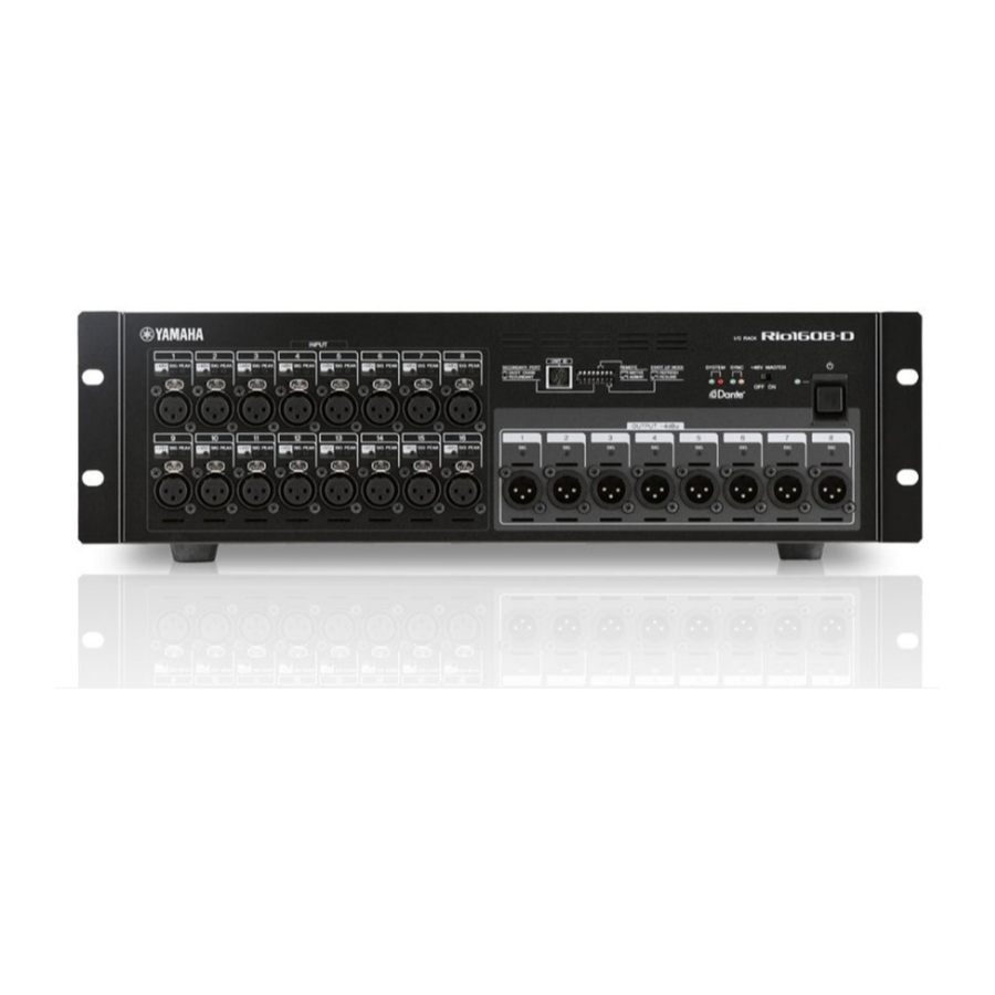
Rio1608-D PANEL LAYOUT (パネルレイアウト) Front Panel(フロントパネル) ui o !0 !1 q [INPUT] Connectors 1–16 q [INPUT] (インプット) 端子 1 ∼ 16 w [+48V] Indicators w [+48V] インジケーター e [SIG] (Signal) Indicators e [SIG] (シグナル) インジケーター r [PEAK] Indicators r [PEAK] (ピーク) インジケーター... -
Page 9: Circuit Board Layout(ユニットレイアウト
Rio1608-D ■ CIRCUIT BOARD LAYOUT (ユニットレイアウト) DANTE MODULE 32CH (ダンテモジュール 32CH) DC168 DNTSB16 SHEET SUPPORT DNTCN (シートサポート) DC FAN MOTOR (DC ファンモーター) POWER SUPPLY UNIT (電源ユニット) DNTCN HAAD (INPUT 1-8) HAAD (INPUT 9-16) AC SHIELD ANGLE (AC シールド金具) (OUTPUT 1-8)... -
Page 10: Disassembly Procedure(分解手順
Rio1608-D RTSW PWRSW LEDDA1 (OUTPUT 1-8) LEDAD1 (INPUT 1-8) LEDAD2 (INPUT 9-16) ■ DISASSEMBLY PROCEDURE (分解手順) Precaution(注意事項) * Install the fi lament tape and the harness clamp in the ※ フィラメントテープ、束線止めは、取り外す前と同じように same way as they were before removal. 取り付けてください。 ※ フラットケーブル注意... - Page 11 Rio1608-D Top Cover トップカバー (Time required: About 5 minutes) (所要時間:約 5 分) 1-1. Remove the eight (8) screws marked [1040]. The right 1-1. [1040] のネジ 8 本を外して、左右のラックアング and left rack angle can then be removed. (Fig. 1) ルを外します。 (図 1)...
- Page 12 Rio1608-D DC168 Circuit Board DC168 シート (Time required: About 6 minutes) (所要時間:約 6 分) 2-1. Remove the top cover. (See procedure 1) 2-1. トップカバーを外します。 (1 項参照) 2-2. Remove the screw marked [790] on the rear panel. 2-2. リアパネル側の [790] のネジ 1 本を外します。 (図 2)...
- Page 13 Rio1608-D DANTE MODULE 32CH DNTSB16 (ダンテモジュール 32CH) Photo 2 (写真 2) シートサポート (所要時間:約 6 分) Sheet Support (Time required: About 6 minutes) 4-1. トップカバーを外します。 (1 項参照) 4-1. Remove the top cover. (See procedure 1) 4-2. リアパネル側の [790] のネジ 1 本を外します。 (図 2)...
- Page 14 Rio1608-D [310] x16 [250] x16 [340] x16 Fig. 4 (図 4) [320] [320] [370] AE ANGLE(AE 金具) HAAD (INPUT 1-8) Fig. 5 (図 5) HA ANGLE A [270] [270] (HA 金具 A) HAAD (INPUT 9-16) Fig. 6 (図 6)...
- Page 15 Rio1608-D LEDAD1 Circuit Board (INPUT 1–8), LEDAD1 シート (INPUT 1‒8)、LED レンズ 3P LED LENS (3P) (所要時間:約 6 分) (Time required: About 6 minutes) 8-1. トップカバーを外します。 (1 項参照) 8-1. Remove the top cover. (See procedure 1) 8-2. シートサポートを外します。 (4 項参照) 8-3.
- Page 16 Rio1608-D [100] LEDAD2 [100] [100] LED LENS 3P (LED レンズ 3P) LED LENS 3P LEDAD1 [120] (LED レンズ 3P) [120] [120] RTSW [170] [170] PWRSW [170] [190] LEDDA1 [140] [140] [140] KNOB, POWER SWITCH (PSW ノブ) ESCUTCHEON POWER SWITCH (PSW エスカッション)...
- Page 17 Rio1608-D Power Supply Unit 電源ユニッ ト (Time required: About 7 minutes) (所要時間:約 7 分) 13-1. Remove the top cover. (See procedure 1) 13-1. トップカバーを外します。 (1 項参照) 13-2. Remove the sheet support. (See procedure 4) 13-2. シートサポートを外します。 (4 項参照) 13-3. Remove the four (4) screws marked [440]. The power 13-3.
- Page 18 Rio1608-D AC Inlet Assembly AC インレッ ト Ass’ y (Time required: About 8 minutes) (所要時間:約 8 分) 16-1. Remove the top cover. (See procedure 1) 16-1. トップカバーを外します。 (1 項参照) 16-2. Remove the DNTCN circuit board. (See procedure 14) 16-2. DNTCN シートを外します。 (14 項参照)...
-
Page 19: Lsi Pin Description(Lsi 端子機能表
Rio1608-D LSI PIN DESCRIPTION(LSI 端子機能表) 88E6350R (YD688A00) GIGABIT ETHERNET SWITCHING HUB .............24 AK4396VF-E2 (X8324A00) DAC (Digital to Analog Converter) ............25 AK5385BVF-E2 (X5364B00) ADC (Analog to Digital Converter) ............25 DM9000AEP (X7029A00) LAN CONTROLLER ..................25 LCMXO2280C-3TN144C (YE064B00) CPLD (Complex Programmable Logic Device) .......23 M38039G4H-820HP (YE032100) CPU (EC) ..................19... - Page 20 Rio1608-D R8A02032BG ( X8810A00 ) CPU ( SWX02 ) DNTSB16: IC001 OUTER OUTER NAME FUNCTION NAME FUNCTION PLL analog ground Ground VSSPLL Wave memory data bus 6 ADC analog input 2 Wave memory data bus 7 ADC analog input 1...
- Page 21 Rio1608-D OUTER OUTER NAME FUNCTION NAME FUNCTION MA15 Wave memory address bus 15 Parallel port A6 MA16 Wave memory address bus 16 Parallel port A7 MA17 Wave memory address bus 17 VCCQ Power supply +3.3 V MA18 Wave memory address bus 18...
- Page 22 Rio1608-D YSS919C-FZ (XZ693C00) DSP7 (Digital Signal Processor) DNTSB16: IC401 NAME FUNCTION NAME FUNCTION PLLEN PLL enable input (0: PLL unuse, 1: PLL use) SIO32 /TEST Test mode setting (0: TEST, 1: Normal) SIO33 AVss Analog ground SIO34 PLL filter SIO35...
- Page 23 Rio1608-D LCMXO2280C-3TN144C (YE064B00) CPLD (Complex Programmable Logic Device) DNTSB16: IC302 NAME FUNCTION NAME FUNCTION PL2A/LUMO_PLLT_FB_A User programmable pin/Optional feedback (PLL) input. T = true PR20B User programmable pin PL2B/LUMO_PLLC_FB_A User programmable pin/Optional feedback (PLL) input C = complement PR20A User programmable pin...
- Page 24 Rio1608-D 88E6350R (YD688A00) GIGABIT ETHERNET SWITCHING HUB DNTSB16: IC503 NAME FUNCTION NAME FUNCTION Column 3 for the LED C3_LED SW_MODE[1] Switch Mode 00=Test mode 01=Reserved Media Dependent Interface [3] P0_MDIN[3] 10=Unmanaged/Forwarding mode 11=CPU Attached/Disable mode P0_MDIP[3] Media Dependent Interface [3]...
- Page 25 Rio1608-D DM9000AEP (X7029A00) LAN CONTROLLER DNTSB16: IC118 NAME FUNCTION NAME FUNCTION BGRES Bandgap pin SD13 Power output +2.5 V SD12 DD25 SD11 Processor data bus TP RX input SD10 RXGND RX ground TXGND TX ground Digital power supply +3.3 V...
-
Page 26: Circuit Boards(シート基板図
Rio1608-D YLD330-EZE2 (YC111A00) LED DRIVER LEDAD1: IC102, LEDAD2: IC202 NAME FUNCTION NAME FUNCTION Ground OUTN4 Output Current Drivers Serial Data Input OUTN5 Output Current Drivers Serial Data Clock OUTN6 Output Current Drivers Serial Data Load OUTN7 Output Current Drivers Output Current Drivers... - Page 27 Rio1608-D Scale: 85/100 DA Circuit Board Component side(部品側) 2NA-WY64350...
- Page 28 Rio1608-D DC168 Circuit Board 2NA-WZ28020...
- Page 29 Rio1608-D Component side(部品側) 2NA-WZ28020...
- Page 30 Rio1608-D Scale: 80/100 DNTSB16 Circuit Board to HAAD-CN901 (CH1-8) to DNTCN-CN101 to DANTE MODULE 32CH to DA-CN902 to LEDDA1-CN301 Component side(部品側) 2NA-WY64760...
- Page 31 Rio1608-D Scale: 80/100 DNTSB16 Circuit Board Pattern side(パターン側) 2NA-WY64760...
- Page 32 Rio1608-D HAAD Circuit Board to DNTSB16-CN601 to DC168-CN703 or DNTSB16-CN602 or DC168-CN704 Component side(部品側) 2NA-WY64340...
- Page 33 Rio1608-D HAAD Circuit Board Pattern side(パターン側) 2NA-WY64340...
- Page 34 Rio1608-D LEDAD1 Circuit Board Component side(部品側) LEDAD1: 2NA-WY68000...
- Page 35 Rio1608-D LEDAD2 Circuit Board Component side(部品側) LEDAD2: 2NA-WY68000...
- Page 36 Rio1608-D LEDDA1 Circuit Board Component side(部品側) LEDDA1: 2NA-WY68000...
- Page 37 Rio1608-D DNTCN Circuit Board PWRSW Circuit Board Component side(部品側) Component side(部品側) RTSW Circuit Board Component side(部品側) DNTCN: 2NA-WY64770 PWRSW: 2NA-WY64770 RTSW: 2NA-WY64770...
-
Page 38: Test Program(テストプログラム
• NETWORK terminal DIAG startup mode Make settings for the DIP switch and UNIT ID switch of Rio1608-D (subject to test) and Rio1608-D (Test jig). * Turn off the power when setting the DIP switch. If the power is turned on, no setting will be refl ected. - Page 39 Rio1608-D 1-6. Details of applications Test result is NG Select the item to Test result is OK Version information, etc. are shown. Test items are displayed. individual check. [F1]START : Start a test [F2]PAUSE : Temporarily stops a test The check result in detail is...
- Page 40 Rio1608-D Menu Tool bar Description Folder up Moves to the folder just abo ve the current folder Large Icons Displays items with large icons Small Icons Displays items with small icons View List Displays items as a list Details Displays items as a detailed list...
- Page 41 Rio1608-D 1-7. List of test items * ○:to be checked ×: Not to be checked Test name Outline of test item Judgment Service Checks boot version Auto ○ Checks Program Version. Auto ○ Checks MAC Address. Auto ○ 01 INFO Checks Sheet ID.
- Page 42 2. Put check marks in all checkboxes. 3. Use this to start testing. 1. Check that [Rio1608-D-Service] is selected in the tree window. * If it is not selected, select [Rio1608-D-Service]. 2. Check that all items to be checked are marked with check marks in the list window.
- Page 43 00-11-22-33-44-55 None Serial No. RIO1608D01 Serial number text • In case of failure Sheet ID 0002 (Rio1608-D) Sheet ID The result is displayed in the OUTPUT window as follows. Item Text indication NG: DIP SW ALL OFF 2-2. SWITCH Test NG: DIP SW 1 Contents: Checks the condition of DIP switch.
- Page 44 Rio1608-D 2-3. LED Test 2-4. ETHERNET Test Contents: Checks if the POWER LED lights up. Contents: Checks the Dante Ethernet (Primary/Secondary) port Checks if the LEDs light up in order from left. and rear LED. Checks if all red LEDs light up.
- Page 45 Rio1608-D 2-5. SDRAM Test 2-6. FAN Test Contents: Checks the address bus of SDRAM. Contents: Checks FAN for operation. Checks the data bus of SDRAM. Checks FAN for stop. Preparation (Example of screen) Back up head amp parameters in advance as necessary.
- Page 46 Rio1608-D 2-7. PLLPU Test 2-8. DSP7 Test Contents: Checks the PLLPU register by reading/writing it. Contents: Checks the condition of address bus by writing/ reading the register of DSP7. (Example of screen) Checks the condition of data bus by writing/reading the register of DSP7.
- Page 47 Rio1608-D 2-9. WORD CLOCK Test OUTPUT result Contents: Checks Word Clock. • Normal condition The result is displayed in the OUTPUT window as follows. (Example of screen) Item Text indication Serial OK: SERIAL Dante IN OK: Dante IN Dante OUT OK: Dante OUT •...
- Page 48 Rio1608-D • In case of failure 2-12. ANALOG test Contents: Checks +48V voltage. The result is displayed in the OUTPUT window as follows. Checks GAIN settings. Item Text indication Checks 9 – 16 channels for loopback. +48V ON NG: +48V ON Checks MUTE settings.
- Page 49 Set the DIP switch to the DIAG mode. No.7 and 8 on, others off. Set the UNIT ID switch to 7. Turn on the power switch of Rio1608-D. INPUT 9–16ch → OUTPUT 1–8ch through mode 3-2. Starting method to OUTPUT analog input (9–16ch) signals to analog OUTPUT (1–8ch)
- Page 50 1-5. ディップスイ ッチと UNIT ID スイ ッチの設定と起動 1-2-1. インターネッ ト プロ トコル (TCP/IP)のプロパテ ィを • NETWORK 端子ダイアグ起動モード 開きます。 Rio1608-D (検査対象)と Rio1608-D (検査治具)のデ ィ ッ プスイ ッチと UNIT ID スイ ッチを設定します。 ※ ディ ップスイ ッチの設定は電源オフの状態で行ってくださ い。電源オンの状態で変更しても設定が反映されません。 1) デ ィ ップスイ ッチをダイアグモードに設定します。...
- Page 51 Rio1608-D 1-6. アプリケーション説明 q タイ トルバー アプリケーションのタイ トルが表示されます。 w タイ トルボタン ウインドウ操作を行うボタンが表示されます。 ボタンは左から 「最小化」 、 「最大化」 、 「閉じる」です。 e メニューバー メニュー一覧が表示されます。 メニュー詳細は以下の通りです。 メニュー ツールバー ツールバー説明 Save OUTPUT アウ ト プッ トの内容をファイルに保存 File Save log ログの内容をファイルに保存 Exit アプリケーションを終了 Execute 単一検査の実行 Start 検査の開始...
- Page 52 Rio1608-D メニュー ツールバー ツールバー説明 Folder up 1つ上のフォルダへ移動 Large Icons リス トを大きいアイコンで表示 Small Icons リス トを小さいアイコンで表示 View List リス トを一覧で表示 Details リス トを詳細で表示 Options 各種オプションの設定を行います Help About アプリケーションのバージョン情報を表示 r ツールバー i アウトプッ トウインドウ コマンドボタンが表示されます。 実機との通信内容等の文字列が表示されます。 このウインドウは表示/非表示の切り替え、及びフロー フォ ン トの種類及び文字色の変更は [表示] - [ オプション]...
- Page 53 Rio1608-D 1-7. 検査項目一覧 ※ ○:検査する/×:検査しない 検査項目 検査概要 判定 サービス Boot Version 確認。 自動 ○ Program Version 確認。 自動 ○ MAC Address 確認。 自動 ○ 01 INFO Sheet ID 確認。 自動 ○ Serial No. 確認。 自動 ○ CPLD Version 確認。 自動...
- Page 54 ※ 検査対象を絞りたい場合は、検査対象だけにチェック印をつけます。 3. 下記のいずれかの方法で検査を開始します。 • ツールバーの [Start] をクリックします。 • ファ ンクションキーの [START] をクリックします。 • キーボードの [F 1 ] を押します。 • メニューバーの [Test] - [Start] をクリックします。 1-9. 検査終了後のディップスイ ッチ設定方法 1. ディ ップスイ ッチを通常モードに設定します。 全て off 2. Rio1608-D の Power スイ ッチをオフします。...
- Page 55 MAC Address 00-11-22-33-44-55 なし • 故障時 Serial No. RIO1608D01 シリアル番号文字列 アウ ト プッ ト ウインドウへ下記の通り表示します。 Sheet ID 0002 (Rio1608-D) Sheet ID 項目 表示文字列 NG: DIP SW ALL OFF NG: DIP SW 1 2-2. SWITCH 検査 NG: DIP SW 2 内容 DIP SW の状態を検査します。...
- Page 56 Rio1608-D 2-3. LED 検査 2-4. ETHERNET 検査 内容 POWER LED が点灯するか検査を行います。 内容 Dante Ethernet ( Primary/Secondary)ポー ト及びリ LED を左から順に点灯するか検査を行います。 ア LED の検査を行います。 赤の LED が全点灯するか検査を行います。 注意事項 緑の LED が全点灯するか検査を行います。 検査者によって Secondary ポー トのケーブルの抜き差しがあ オレンジの LED が全点灯するか検査を行います。 る為、表示されるダイアログに従って操作を行ってください。 LED が全点灯するか検査を行います。 下記のダイアログが表示されたとき、 Secondaryポー トのケー...
- Page 57 Rio1608-D 2-5. SDRAM 検査 2-6. FAN 検査 内容 SDRAM のアドレスバスの検査を行います。 内容 FAN の動作検査を行います。 SDRAM のデータバスの検査を行います。 FAN の停止検査を行います。 事前準備 〈画面例〉 必要に応じ、ヘッ ドアンプパラメータをバックアップしてくだ さい。 〈画面例〉 出力結果 • 正常時 アウ ト プッ ト ウインドウへ下記の通り表示します。 出力結果 項目 表示文字列 • 正常時 Fan Normal OK: Fan Normal アウ...
- Page 58 Rio1608-D 2-7. PLLPU 検査 2-8. DSP7 検査 内容 PLLPU レジスタの読み書きテス トを実行します。 内容 DSP7 の Register を Write/Read してアドレスバス の良否を検査します。 〈画面例〉 DSP7 の Register を Write/Read してデータバスの 良否を検査します。 DSP7 の Register を Write/Read して Chip Select の良否を検査します。 〈画面例〉 出力結果 • 正常時...
- Page 59 Rio1608-D 2-9. WORD CLOCK 検査 出力結果 内容 WORD CLOCK の検査を行います。 • 正常時 アウ ト プッ ト ウインドウへ下記の通り表示します。 〈画面例〉 項目 表示文字列 Serial OK: SERIAL Dante IN OK: Dante IN Dante OUT OK: Dante OUT • 故障時 アウ ト プッ ト ウインドウへ下記の通り表示します。...
- Page 60 Rio1608-D 2-12. ANALOG 検査 • 故障時 内容 +48V 電圧の検査を行います。 アウ ト プッ ト ウインドウへ下記の通り表示します。 GAIN 設定の検査を行います。 項目 表示文字列 9-16ch のループバック検査を行います。 +48V ON NG: +48V ON MUTE 設定の検査を行います。 +48V OFF NG: +48V OFF バリピッチ (42.336kHz, 100kHz)設定の検査を行い GAIN MAX NG: GAIN M ます。...
- Page 61 1) デ ィ ップスイ ッチをダイアグモードに設定する。 7, 8 番を on、その他は off 2) UNIT ID スイ ッチを 7 に設定します。 3) Rio1608-D の Power スイ ッチをオンにします。 3-2. INPUT9 ∼ 16ch → OUTPUT1 ∼ 8ch スルーモード アナログインプッ ト (9 ∼ 16ch) の信号をアナログアウ ト プッ ト...
- Page 62 Rio1608-D ■ INSPECTIONS 1. Preparations 2. ANALOG IN/OUT Test 2-1. INPUT 1 – 8 → OUTPUT 1 – 8 1-1. Settings The ANALOG test of the test program is used for the ANALOG Parameters: Input analog signals from the CHn (n=1–8) input IN/OUT characteristic test.
- Page 63 Rio1608-D 2-2. Vari pitch sound signal test B. GAIN MAX Input an analog signal from CH1 INTPUT and measure the 1 Gain (INPUT 1–16) output signal from the CH1 OUTPUT. Input Specifi ed Permissible Input Level Frequency Output Level Range...
- Page 64 Rio1608-D 3. Fan Check Check that the fan rotating speed increases when the FAN HIGH, LOW switch on the rear panel is set to the HIGH side and that the fan rotating speed decreases when set to the LOW side.
- Page 65 Rio1608-D 検査 1. 準備 2. ANALOG IN / OUT 検査 1-1. 設定 2-1. INPUT 1 − 8 → OUTPUT 1 − 8 テストプログラムの ANALOG 検査を使用して、ANALOG 条件 CHn (n= 1 − 8)入力からアナログ信号を入力し、 IN/OUT 特性検査を行います。テス ト プログラム (50 ページ) CHn (n= 1 − 8)出力から出力される信号を計測...
- Page 66 Rio1608-D 2-2. バリピッチ音声信号検査 B. GAIN MAX 1 利得 (INPUT 1 − 16) CH1入力からアナログ信号を入力し、CH1出力から出力 される信号を計測します。 入力周波数 入力レベル 規定出力レベル 許容範囲 1 kHz ‒62 dBu +4 dBu +4 ± 2 dBu 利得 WORD 入力 入力 規定出力 2 歪率 (INPUT 1 − 16) 許容範囲...
- Page 67 Rio1608-D 3. ファ ンの確認 リアパネルにある FAN HIGH、LOW のスイッチを HIGH 側に切り替えたとき、ファンの回転数が速くなり、LOW 側 に切り替えたとき、ファンの回転数が遅くなることを確認し ます。 4. 出荷時の設定 フロントパネル • POWER SWITCH:OFF にします。 • +48V MASTER:OFF にします。 • DIP SWITCH:全てのスイ ッチを上側にします。 • ROTARY SWITCH:1 にします。 リアパネル • FAN SWITCH:LOW にします。...
-
Page 68: Updating Firmware
Start the application program for updating. When “update.exe” is activated, the screen as shown below will 1-4. Connection Connect the PC and Primary port of Rio1608-D with Ethernet appear. (CAT5e) straight cable. * Only the above connection is required. Do not connect anything to other terminals. - Page 69 2-10. In case of updating failed If an error occurs during writing or writing is not fi nished after a long time, end the application once, restart Rio1608-D and perform the fi rmware updating procedure from the beginning.
- Page 70 Rio1608-D 2-11. List of errors and warnings Error No. Description Command transmission was failed. (Securement of communication pathway) [ERROR:001] Command transmission failed (to secure communication passage). Command transmission was failed. (Acquisition of communication control authority) [ERROR:002] Command transmission failed (to obtain communication control right).
-
Page 71: ファームウェアのアップデート
• PROG 用:¥Firmware¥prog¥RIO_PROG.BIN ア ップデー ト対象のアプリケーションを起動してください。 バージョンが違う場合は、最新にア ップデー トしてください。 update.exe を起動すると下記の画面が表示されます。 1-4. 接続方法 パ ソ コ ン と Rio1608-D の Primary ポ ー ト を Ethernet (CAT5e)ス トレー トケーブルで接続します。 ※ 上記のみを接続し、それ以外の端子には何も接続しない でください。 2-3. アップデート ファーム情報確認 File box 内の 「product name:」 、 「version:」が正しく表示さ... - Page 72 実機にア ップデー ト ファイルの転送が始まり、FLASH ROM に書き込まれます。 〈画面例〉 2-8. アプリケーション終了 右上の [×] ボタンを押し、アプリケーションを終了します。 2-9. Rio1608-D の電源オフ 1) デ ィ ップスイ ッチを通常モードに設定します。 全て off 2-6. アップデート中 2) Rio1608-D の Power スイ ッチをオフにします。 「updating fi rmware...」と表示され、進行状況もプログレス バーに表示されます。 2-10. アップデート失敗時 書き込み中にエラーが発 生した時や、長時間待っても書 き込みが完了しない時は、アプリケーションを一旦終了し、 Rio1608-D を再起動後、ファームウェアアップデートを最初 からやり直します。...
- Page 73 Rio1608-D 2-11. エラー・警告一覧 エラー番号 内容 Command transmission was failed. (Securement of communication pathway ) [ERROR:001] 通信経路確保コマンド送信を失敗しました。 Command transmission was failed. (Acquisition of communication control authority) [ERROR:002] 通信制御権取得コマンド送信に失敗しました。 Command transmission was failed. (Control authority open) [ERROR:003] 制御権開放コマンド送信に失敗しました。 Command transmission was failed.
-
Page 74: Initialization(イニシャライズ
ドに設定します。 No.5, 6 on, others off 5、6 番を on、その他は off Turn on the power switch of Rio1608-D. 2) Rio1608-D の Power スイ ッチをオンにします。 Wait until the system LED (green) lights up, which 3) DANTE モジュールのイニシャライズが正常に終った事 indicates that initialization of the DANTE module has を示す... -
Page 75: Updating Dante Module (Brooklyn2)
1-4. Connection Using Firmware Update Manager provided by Audinate, Connect the PC and primary port of Rio1608-D with Ethernet execute updating Dante firmware. (Start in the order of Start (CAT5e) straight cable. menu – Program – Audinate – Dnte Firmware Update Manager * Only the above connection is required and nothing –... - Page 76 Press the [OK] button, and the screen display will be as shown Put a check mark at the left end of Rio1608-D to be updated. below. At this time, do not select more than one but execute updating (“Update Done”...
-
Page 77: Dante モジュール (Brooklyn2) のアップデート
Audinate 社提供の Firmware Update Manager にて Dante 1-4. 接続方法 ファームウェアのア ップデートを実施します (スタート メニュー パ ソ コ ン と Rio1608-D の Primary ポ ー ト を Ethernet ‒ プログラム ‒ Audinate ‒ Dante Firmware Update (CAT5e)ス トレー トケーブルで接続します。 Manager - Dante Firmware Update Manager で起動) 。... - Page 78 • ¥Rio1608-D¥brooklyn2¥FWUpdate_Rio1608-D_ vxxxx_swxxx.dnt (xxxx, xxx はバージョン番号) 。 2-6. アップデート完了 ア ップデー トが完了すると確認のポップア ップが表示されます。 エラーがあった場合は 3. を参照してください。 2-4. デバイスの選択 ネッ トワーク接続された Rio1608-D が見つかると、 ア ップデー [OK]ボタンを押すと以下の画面表示となります (Status ト対象として一覧表示されます。 欄に “Update Done”を表示) 。 対象となる Rio1608-D の左端にチェックをつけます。 この時複数選択はせずに、1 台ずつア ップデー ト作業を行っ てください。 2-7. アプリケーションの終了...
-
Page 79: Procedure To Write The Serial Number
Make sure that there is nothing written after “bar-code input:”. • ¥Rio1608-D¥tools¥serbar2¥serbar2.exe * If there is, click on “clear”. 1-4. Connection Connect the PC and Primary port of Rio1608-D with Ethernet (CAT5e) straight cable. * Only the above connection is required. Do not connect anything to other terminals. 2-4. - Page 80 Press the [X] button at the upper right to end the application If an error occurs during writing or writing is not finished program. after a long time, end the application once, restart Rio1608-D and perform the serial number writing procedure from the beginning again.
-
Page 81: 製造番号の書き込み手順
シリアル番号入力 ダウンロードし、C ドライブ直下にコピーしてください。 「bar-code input:」の欄に何も書かれていない事を確認しま • ¥Rio1608-D¥tools¥serbar2¥serbar2.exe す。 ※ 書かれていた場合は、 「clear」をクリックします。 1-4. 接続方法 パ ソ コ ン と Rio1608-D の Primary ポ ー ト を Ethernet (CAT5e)ス トレー トケーブルで接続します。 ※ 上記のみを接続し、それ以外の端子には何も接続しない でください。 2-4. シリアル番号書き込み開始 “21”を入力し、続いて Rio 本体のシリアル番号をキーボー ドを使って打ち込み、 「writing」をクリックします。 Rio1608-D 2. - Page 82 右上の [×] ボタンを押し、アプリケーションを終了します。 書き込み中にエラーが発 生した時や、長時間待っても書 き込みが完了しない時は、アプリケーションを一旦終了し、 2-7. Rio1608-D の電源オフ Rio1608-D を再起動後、シリアル番号書き込みを最初から 1) デ ィ ップスイ ッチを通常モードに設定します。 やり直します。 全て off 2) Rio1608-D の Power スイ ッチをオフにします。 2-9. エラー・警告一覧 エラー番号 内容 Command transmission was failed. (Securement of communication pathway ) [ERROR:001] 通信経路確保コマンド送信を失敗しました。...
-
Page 83: Starting Sequence(起動シーケンス
UNIT ID set to [7] or [8]. Starting is judged on the Boot side. 1. Turn on the power switch of Rio1608-D. DIP switch [5] ON, [6] ON, others 2. Wait until the SYSTEM LED (green) turns on (about 1 minute). - Page 84 Rio1608-D ● Starting mode (Flow chart) Normal mode Firmware Update mode Diag mode DIP switch [7] OFF [8] OFF(Refresh) DIP switch DIP switch [7] ON [8] OFF(Resume) [7] OFF [8] ON [7] ON [8] ON [5] ON [6] OFF(AD8HR) Power ON...
- Page 85 UNIT ID は [7] か [8] に設定 起動判断は Boot 側でされる。 ディップスイッチ [5]ON、[6]ON、 1. Rio1608-D の Power スイッチをオンにします。 INITIALIZATION その他は OFF 2. SYSTEM LED(緑)が点灯するのを待ちます。 (約 1 分) モード UNIT ID は [0] に設定 3. SYSTEM LED (緑) の点灯を確認後、 Rio1608-D の Power スイッチをオフにします。...
- Page 86 Rio1608-D ● 起動モード(フロー) 通常モード ファームUpdateモード Diagモード ディップスイッチ [7] OFF [8] OFF(Refresh) ディップスイッチ ディップスイッチ [7] ON [8] OFF(Resume) [7] OFF [8] ON [7] ON [8] ON [5] ON [6] OFF(AD8HR) 電源ON Boot Program起動 検査基板の有無確認 有りの場合、起動モードはダイ アグになる (有り) 起動モードがアップデートの場合 パネルLEDアップデート表示 アップデート処理 電源断...
-
Page 87: Memory Initialization(メモリ初期化
Rio1608-D ■ MEMORY INITIALIZATION (メモリ初期化) ● Contents of initialization Subject to Subject to initialization (SWX02 or up) initialization (Brooklyn2) Initializing method Brooklyn Brooklyn Gain 2 setting +48V HA Gain GC Gain 2 setting On/Off Freq On/Off Trim Master (other than... -
Page 88: Parts List
I/O RACK PARTS LIST CONTENTS(目次) OVERALL ASSEMBLY(総組立) ............2 ELECTRICAL PARTS(電気部品) ..........6–37 Notes : DESTINATION ABBREVIATIONS A : Australian model M : South African model B : British model O : Chinese model C : Canadian model P : Blazillian model D : German model Q : South-east Asia model E : European model... - Page 89 Rio1608-D OVERALL ASSEMBLY (総組立) 1050 1030 1010 1020 1020 1040 1020 1020 1030 850a 1040 850b 550a 550b...
- Page 90 Rio1608-D ※ I n s t a l l L E D l e n s e s m a r k e d [60] and [70] to the front panel marked [40] first, using double coated adhesive tape. Then i n s t a l l L E D c i r c u i t s b o a r d s marked [90], [110] and [130].
- Page 91 DESCRIPTION 部 品 名 REMARKS REF NO. QTY RANK OVERALL ASSEMBLY 総 組 立 Rio1608-D OVERALL ASSEMBLY 総 組 立 (WY20800) ZA148000 BOTTOM CHASSIS ボ ト ム シ ャ ー シ 加 工 品 WH917800 RUBBER FOOT ARMSTRONG K29 ゴ...
- Page 92 Rio1608-D PART NO. DESCRIPTION 部 品 名 REMARKS REF NO. QTY RANK WZ980800 DC FAN MOTOR 9S0824F4D04 D C フ ァ ン モ ー タ ー ZD385600 BIND HEAD SCREW 4.0X40 MFNI33 SP 小 ネ ジ + B I N D...
- Page 93 PART NO. DESCRIPTION 部 品 名 REMARKS REF NO. QTY RANK ELECTRICAL PARTS 電 気 部 品 Rio1608-D WY643500 CIRCUIT BOARD D A シ ー ト (YD588C0) WZ280200 CIRCUIT BOARD DC168 D C 1 6 8 シ ー ト (YD667C0)
- Page 94 Rio1608-D PART NO. DESCRIPTION 部 品 名 REMARKS REF NO. QTY RANK C405 WB57410R POLYESTER FILM CAP. (CHIP) .00018 50V J RECT. チ ッ プ マ イ ラ ー C406 WB575000 POLYESTER FILM CAP. (CHIP) 0.0010 50V J RECT. チ ッ プ マ イ ラ ー...
- Page 95 Rio1608-D PART NO. DESCRIPTION 部 品 名 REMARKS REF NO. QTY RANK C918 US14510R CERAMIC CAPACITOR (CHIP) 0.1000 25V Z RECT. チ ッ プ セ ラ( F ) C919 UU267100 ELECTROLYTIC CAPACITOR 10.00 50.0V RX TP ケ ミ コ ン F W...
- Page 96 Rio1608-D PART NO. DESCRIPTION 部 品 名 REMARKS REF NO. QTY RANK IC907 XJ598A0R IC NJM78L05UA-TE1 I C REGULATOR +5V -910 XJ598A0R IC NJM78L05UA-TE1 I C REGULATOR +5V JK101 WR264400 CONNECTOR XLR JACK NC3MAAH キ ャ ノ ン コ ネ ク タ OUTPUT +4dBu 1...
- Page 97 Rio1608-D PART NO. DESCRIPTION 部 品 名 REMARKS REF NO. QTY RANK R218 RF35718R CARBON RESISTOR (CHIP) 18.0K D 1608 チ ッ プ 抵 抗 R219 RD15475R CARBON RESISTOR (CHIP) 75.0 1/4 J TP チ ッ プ 抵 抗 R220 RD15475R CARBON RESISTOR (CHIP) 75.0 1/4 J TP...
- Page 98 Rio1608-D PART NO. DESCRIPTION 部 品 名 REMARKS REF NO. QTY RANK R507 RF35639R CARBON RESISTOR (CHIP) 3.9K D 1608 チ ッ プ 抵 抗 R508 RF356560 CARBON RESISTOR (CHIP) 5.6K D 1608 チ ッ プ 抵 抗 R509 RF35439R CARBON RESISTOR (CHIP) 39.0 D 1608...
- Page 99 Rio1608-D PART NO. DESCRIPTION 部 品 名 REMARKS REF NO. QTY RANK R723 RD257100 CARBON RESISTOR (CHIP) 10.0K 0.1 J RECT. チ ッ プ 抵 抗 R724 RD257100 CARBON RESISTOR (CHIP) 10.0K 0.1 J RECT. チ ッ プ 抵 抗...
- Page 100 Rio1608-D DC168 PART NO. DESCRIPTION 部 品 名 REMARKS REF NO. QTY RANK WZ280200 CIRCUIT BOARD DC168 D C 1 6 8 シ ー ト (YD667C0) C001 WM489900 CERAMIC CAPACITOR (CHIP) 10.0000 35V M KAKU チ ッ プ セ ラ コ ン...
- Page 101 Rio1608-D DC168 PART NO. DESCRIPTION 部 品 名 REMARKS REF NO. QTY RANK C441 V585100R CERAMIC CAPACITOR (CHIP) 470P 50V J KAKUTE チ ッ プ セ ラ C H C442 US044220 CERAMIC CAPACITOR (CHIP) 0.0220 25V K RECT. チ ッ プ セ ラ( B )...
- Page 102 Rio1608-D DC168 PART NO. DESCRIPTION 部 品 名 REMARKS REF NO. QTY RANK IC331 YD513A00 IC LM5575MHX I C SWITCHING REGULATOR IC381 X8375A00 IC TC7SHU04FU I C INVERTER IC382 X9395A00 IC LM5576MHX I C SWITCHING REGULATOR IC441 YA632A00 IC LM5001MA I...
- Page 103 Rio1608-D DC168 and DNTCN/PWRSW/RTSW PART NO. DESCRIPTION 部 品 名 REMARKS REF NO. QTY RANK R305 RD357150 CARBON RESISTOR (CHIP) 15.0K 63M J RECT. チ ッ プ 抵 抗 R306 RD358100 CARBON RESISTOR (CHIP) 100.0K 63M J RECT. チ ッ...
- Page 104 Rio1608-D DNTCN/PWRSW/RTSW and DNTSB16 PART NO. DESCRIPTION 部 品 名 REMARKS REF NO. QTY RANK IC302 X5825B00 IC SN74LVC1G32DCKR I C IC302 XW633A0R IC TC7SH32FU(TE85L,JF) I C IC302 YD169A00 IC TC7SZ32FU(TE85L,F) I C IC302 YE493A00 IC SN74LVC1G32DCK3 I C IC302...
- Page 105 Rio1608-D DNTSB16 PART NO. DESCRIPTION 部 品 名 REMARKS REF NO. QTY RANK -258 US635100 CERAMIC CAPACITOR (CHIP) 0.100 16V Z RECT. チ ッ プ セ ラ( F ) C259 WD758300 CERAMIC CAPACITOR (CHIP) 10U 10V K RECT. チ ッ...
- Page 106 Rio1608-D DNTSB16 PART NO. DESCRIPTION 部 品 名 REMARKS REF NO. QTY RANK C535 WG251600 CERAMIC CAPACITOR (CHIP) 4.7 6.3V K RECT. チ ッ プ セ ラ C536 US635100 CERAMIC CAPACITOR (CHIP) 0.100 16V Z RECT. チ ッ プ セ ラ( F )...
- Page 107 Rio1608-D DNTSB16 PART NO. DESCRIPTION 部 品 名 REMARKS REF NO. QTY RANK IC012 X3516A0R IC SN74LV11APWR I C AND IC101 XU797B01 IC TC74VHC245FT I C TRANSCEIVER IC102 XU797B01 IC TC74VHC245FT I C TRANSCEIVER IC104 X3848A0R IC S-80130ANMC-JCPT2G I C SYSTEM RESET...
- Page 108 Rio1608-D DNTSB16 PART NO. DESCRIPTION 部 品 名 REMARKS REF NO. QTY RANK R153 RD454220 CARBON RESISTOR (CHIP) 22.0 63M J RECT. チ ッ プ 抵 抗 R155 RD454220 CARBON RESISTOR (CHIP) 22.0 63M J RECT. チ ッ プ 抵...
- Page 109 Rio1608-D DNTSB16 PART NO. DESCRIPTION 部 品 名 REMARKS REF NO. QTY RANK R517 RD455100 CARBON RESISTOR (CHIP) 100.0 63M J RECT. チ ッ プ 抵 抗 R518 RA157100 CARBON RESISTOR (CHIP) 10.0K 63M D RECT. チ ッ プ 金 被 抵 抗...
- Page 110 Rio1608-D DNTSB16 and HAAD PART NO. DESCRIPTION 部 品 名 REMARKS REF NO. QTY RANK X102 WM135400 RESONATOR QUARTZ 25MHz DSX321G 水 晶 振 動 子 X301 WM885800 RESONATOR QUARTZ 45.1584MHz SG-310SCF 水 晶 発 振 器 X302 WM885900 RESONATOR QUARTZ 49.152MHz SG-310SCN...
- Page 111 Rio1608-D HAAD PART NO. DESCRIPTION 部 品 名 REMARKS REF NO. QTY RANK C231 US062220 CERAMIC CAPACITOR (CHIP) 220P 50V J RECT. チ ッ プ セ ラ( S L ) C232 US062220 CERAMIC CAPACITOR (CHIP) 220P 50V J RECT. チ ッ プ セ ラ( S L )...
- Page 112 Rio1608-D HAAD PART NO. DESCRIPTION 部 品 名 REMARKS REF NO. QTY RANK C434 UU26722R ELECTROLYTIC CAPACITOR 22.00 50.0V RX TP ケ ミ コ ン F W C502 UR877470 ELECTROLYTIC CAPACITOR 47.00 63.0V RX TP ケ ミ コ ン C503 VJ09740R ELECTROLYTIC CAPACITOR 10.00 50.0V TATETE...
- Page 113 Rio1608-D HAAD PART NO. DESCRIPTION 部 品 名 REMARKS REF NO. QTY RANK C704 VJ09740R ELECTROLYTIC CAPACITOR 10.00 50.0V TATETE ケ ミ コ ン K L C705 V585100R CERAMIC CAPACITOR (CHIP) 470P 50V J KAKUTE チ ッ プ セ ラ C H...
- Page 114 Rio1608-D HAAD PART NO. DESCRIPTION 部 品 名 REMARKS REF NO. QTY RANK C907 UU268100 ELECTROLYTIC CAPACITOR 100.00 50.0V RX TP ケ ミ コ ン F W C908 UU268100 ELECTROLYTIC CAPACITOR 100.00 50.0V RX TP ケ ミ コ ン F W...
- Page 115 Rio1608-D HAAD PART NO. DESCRIPTION 部 品 名 REMARKS REF NO. QTY RANK IC106 X5364B00 IC AK5385BVF-E2 I C ADC IC202 X3505A00 IC NJM2068M-D(TE2) I C OP AMP IC203 XV944A00 IC TC74HC4053AFT(EL) I C MULTIPLEXER IC204 X3505A00 IC NJM2068M-D(TE2) I...
- Page 116 Rio1608-D HAAD PART NO. DESCRIPTION 部 品 名 REMARKS REF NO. QTY RANK R112 VP443800 METAL FILM RESISTOR 100.0K 1/4 F AX26 金 属 被 膜 抵 抗 R113 RD256470 CARBON RESISTOR (CHIP) 4.7K 0.1 J RECT. チ ッ プ...
- Page 117 Rio1608-D HAAD PART NO. DESCRIPTION 部 品 名 REMARKS REF NO. QTY RANK R231 WA02670R CARBON RESISTOR (CHIP) 10.0K 1/10 D RECT. チ ッ プ 金 皮 抵 抗 R232 WA02670R CARBON RESISTOR (CHIP) 10.0K 1/10 D RECT. チ ッ プ 金 皮 抵 抗...
- Page 118 Rio1608-D HAAD PART NO. DESCRIPTION 部 品 名 REMARKS REF NO. QTY RANK -354 RD255100 CARBON RESISTOR (CHIP) 100.0 0.1 J RECT. チ ッ プ 抵 抗 R355 RD257100 CARBON RESISTOR (CHIP) 10.0K 0.1 J RECT. チ ッ プ 抵...
- Page 119 Rio1608-D HAAD PART NO. DESCRIPTION 部 品 名 REMARKS REF NO. QTY RANK R514 RD254100 CARBON RESISTOR (CHIP) 10.0 0.1 J RECT. チ ッ プ 抵 抗 R515 RD254100 CARBON RESISTOR (CHIP) 10.0 0.1 J RECT. チ ッ プ 抵...
- Page 120 Rio1608-D HAAD PART NO. DESCRIPTION 部 品 名 REMARKS REF NO. QTY RANK R633 RD25439R CARBON RESISTOR (CHIP) 39.0 0.1 J RECT. チ ッ プ 抵 抗 R634 WA02590R CARBON RESISTOR (CHIP) 2.7K 1/10 D RECT. チ ッ プ 金 皮 抵 抗...
- Page 121 Rio1608-D HAAD PART NO. DESCRIPTION 部 品 名 REMARKS REF NO. QTY RANK R756 RD256470 CARBON RESISTOR (CHIP) 4.7K 0.1 J RECT. チ ッ プ 抵 抗 R757 RD256470 CARBON RESISTOR (CHIP) 4.7K 0.1 J RECT. チ ッ プ 抵...
- Page 122 Rio1608-D HAAD PART NO. DESCRIPTION 部 品 名 REMARKS REF NO. QTY RANK RA904 RE04747R RESISTOR ARRAY 47KX4 抵 抗 ア レ イ -910 RE04747R RESISTOR ARRAY 47KX4 抵 抗 ア レ イ RY101 VU685600 RELAY DC NA-5W-K 5V 2A UC リ...
- Page 123 Rio1608-D HAAD and LEDAD1/LEDAD2/LEDDA1 PART NO. DESCRIPTION 部 品 名 REMARKS REF NO. QTY RANK TR703 WC529400 TRANSISTOR (CHIP) 2SCKTC3875S-Y,GR-RTK ト ラ ン ジ ス タ 2 S C TR704 WC529400 TRANSISTOR (CHIP) 2SCKTC3875S-Y,GR-RTK ト ラ ン ジ ス タ 2 S C...
- Page 124 Rio1608-D LEDAD1/LEDAD2/LEDDA1 PART NO. DESCRIPTION 部 品 名 REMARKS REF NO. QTY RANK LD205 WY781600 LED (CHIP) GREEN SML-D12M8WT86(N/P) チ ッ プ L E D SIGNAL CH5 LD206 WY781600 LED (CHIP) GREEN SML-D12M8WT86(N/P) チ ッ プ L E D SIGNAL CH6...
-
Page 125: Overall Connector Circuit Diagram
I/O RACK CIRCUIT DIAGRAM CONTENTS (目次) BLOCK DIAGRAM (001-003) (ブロックダイアグラム) ......3-5 GENERAL DIAGRAM (全体図) 001 ....3 DNTSB16, Brooklyn2 002 ....4 HAAD, DA 003 ....5 OVERALL CONNECTOR CIRCUIT DIAGRAM (001-002) (総コネクタ接続回路図) ..............6-7 OVERALL CONNECTOR CIRCUIT DIAGRAM 001 .... -
Page 126: Parts List
Rio1608-D (回路図表記上の注意) (シート間コネクタの読み方について) (信号名) 対応するシート間のコネクタのあるロケーションを示します。 (アルファベットが水平方向、数字が垂直方向) (3桁の数字は信号の行先ページを示します。) (コネクタの接続について) to DNTSB16-CN203 <Page 15: D-3> (Page 15 は回路図のページです。) D-3 は対応するシート間のコネクタのあるロケーションを示します。 (アルファベットが水平方向、数字が垂直方向) Note : See parts list for details of circuit board conponent parts. 注:シートの部品詳細は、パーツリストをご参照ください。 ■ WARNING Components having special characteristics are marked and must be replaced with parts having specifi... -
Page 127: General Diagram(全体図
■ BLOCK DIAGRAM 001 (Rio1608-D) Rio1608-D DNTCN DNTSB16 JK111, 112 JK504,505 JK101 JK102 IC115 (48P) CN101 CN501 See page 4 (4P) (4P) IC118 (48P) IC503 (129P) IC110 (54P) CN201 SW201 IC001 (316P) DC168 (3P) CN205 (13P) X102 X501 X101 IC402 (5P) -
Page 128: Dntsb16, Brooklyn2 002
■ BLOCK DIAGRAM 002 (Rio1608-D) Rio1608-D CN902 (11P) CN903 (8P) HAAD CN901 (23P) CN608 (8P) CN605 (11P) CN605 (11P) HAAD DNTSB16 CN901 (23P) CN601, 602 (23P) IC401 (208P) IC303 IC302 (14P) (144P) DC168 CN205 (13P) CN181 (13P) X302 CN102 X101... -
Page 129: Haad, Da 003
■ BLOCK DIAGRAM 003 (Rio1608-D) Rio1608-D HAAD, DA 28CA1-2001092469-3 ■ BLOCK DIAGRAM 003 (Rio1608-D) -
Page 130: Overall Connector Circuit Diagram 001
■ OVERALL CONNECTOR CIRCUIT DIAGRAM 001 (Rio1608-D) Rio1608-D RTSW DNTCN DNTSB16 DC168 PWRSW Wiring Assembly VH (See page 7) Wiring Assembly AC INLET (See page 7) Wiring Assembly INLD16 (See page 7) LEDAD1 HAAD LEDDA1 Wiring Assembly OUTLD16 (See page 7) -
Page 131: Wiring Diagram Of Connector Assembly (束線結線表) 002
■ OVERALL CONNECTOR CIRCUIT DIAGRAM 002 (Rio1608-D) Rio1608-D Note) The pins in the same in the same line are connected to each other. A pin having no destination for connection is not used. Wiring Diagram of Connector Assembly(束線結線表) ■ OVERALL CONNECTOR CIRCUIT DIAGRAM 002 (Rio1608-D) -
Page 132: Rear Panel Dante Connector 001
■ CNSW (DNTCN) 001 CIRCUIT DIAGRAM (Rio1608-D) Rio1608-D not installed to DNTSB16-CN501 (Page 18: L-3) to DNTSB16-JK504 to DNTSB16-JK505 (Page 18: S-3) (Page 18: R-3) Rear Panel Dante Connector ■ CNSW (DNTCN) 001 CIRCUIT DIAGRAM (Rio1608-D) 28CC1-2001090814-1... -
Page 133: Front Panel Power Switch 002
■ CNSW (PWRSW) 002 CIRCUIT DIAGRAM (Rio1608-D) Rio1608-D Front Panel Power Switch ■ CNSW (PWRSW) 002 CIRCUIT DIAGRAM (Rio1608-D) 28CC1-2001090814-2... -
Page 134: Front Panel Rotary Switch 003
■ CNSW (RTSW) 003 CIRCUIT DIAGRAM (Rio1608-D) Rio1608-D OR GATE D-FF DECODER to DNTSB16-CN104 (Page 14: B-14) TRANSCEIVER TRANSCEIVER not installed TRANSCEIVER Front Panel Rotary Switch ■ CNSW (RTSW) 003 CIRCUIT DIAGRAM (Rio1608-D) 28CC1-2001090814-3... - Page 135 ■ DA CIRCUIT DIAGRAM (Rio1608-D) Rio1608-D not installed not installed to DNTSB16-CN608 (Page 19: B-5) N.C. to DC168-CN701 (Page 13: B-2) DA Converter ■ DA CIRCUIT DIAGRAM (Rio1608-D) N.C. to DNTSB16-CN605 (Page 19: B-6)
-
Page 136: Power Detect, Clock Generator, Dc-Dc Converter 001
■ DCSB (DC168) 001 CIRCUIT DIAGRAM (Rio1608-D) Rio1608-D SYSTEM RESET to POWER SUPPLY UNIT VARIABLE SHUNT REGULATOR INVERTER SWITCHING REGULATOR not installed not installed not installed not installed INVERTER not installed not installed to DNTSB16-CN205 (Page 15: C-9) SWITCHING REGULATOR... -
Page 137: Dc-Dc Converter, Linear Regulator 002
■ DCSB (DC168) 002 CIRCUIT DIAGRAM (Rio1608-D) Rio1608-D SWITCHING REGULATOR not installed to DA-CN001 (Page 11: C-16) REGULATOR +15V SWITCHING REGULATOR not installed not installed not installed REGULATOR -15V not installed SWITCHING REGULATOR not installed not installed to HAAD-CN902 (Page 22: O-8) -
Page 138: Dntsb16 (001-006)
■ DNTSB16 001 CIRCUIT DIAGRAM (Rio1608-D) Rio1608-D TRANSCEIVER TRANSCEIVER to LEDAD1-CN101 (Page 23: G-2) CPU (SWX02) to LEDDA-CN301 TRANSCEIVER (Page 25: H-3) TRANSCEIVER CPU (SWX02) LAN CONTROLLER FLASH MEMORY 32M SYSTEM RESET not installed INVERTER TRANSCEIVER SDRAM 64M to RTSW-CN301... -
Page 139: Cpu 2/2
■ DNTSB16 002 CIRCUIT DIAGRAM (Rio1608-D) Rio1608-D not installed CPU (SWX02) CPU (SWX02) CPU (SWX02) INVERTER not installed not installed to DC168-CN181 REGULATOR +1.2V (Page 12: H-7) not installed CPU 2/2 ■ DNTSB16 002 CIRCUIT DIAGRAM (Rio1608-D) 28CC1-2001087775-2... -
Page 140: Cpld 003
■ DNTSB16 003 CIRCUIT DIAGRAM (Rio1608-D) Rio1608-D TRANSCEIVER TRANSCEIVER not installed NAND GATE not installed not installed CPLD not installed CPLD ■ DNTSB16 003 CIRCUIT DIAGRAM (Rio1608-D) 28CC1-2001087775-3... - Page 141 ■ DNTSB16 004 CIRCUIT DIAGRAM (Rio1608-D) Rio1608-D DSP7 REGULATOR +2.5V DSP7 ■ DNTSB16 004 CIRCUIT DIAGRAM (Rio1608-D) 28CC1-2001087775-4...
-
Page 142: Dante 005
■ DNTSB16 005 CIRCUIT DIAGRAM (Rio1608-D) Rio1608-D GIGABIT ETHERNET SWITCHING HUB not installed not installed not installed not installed to DANTE MODULE 32CH to DNTCN-CN101 (Page 8: F-4) not installed not installed not installed not installed DC-DC CONVERTER DANTE ■ DNTSB16 005 CIRCUIT DIAGRAM (Rio1608-D) -
Page 143: Ad/Da I/F 006
■ DNTSB16 006 CIRCUIT DIAGRAM (Rio1608-D) Rio1608-D not installed to HAAD-CN901 (ANALOG INPUT CH1–8) (Page 22: P-3) to HAAD-CN901 (ANALOG INPUT CH9–16) (Page 22: P-3) to DA-CN903 (ANALOG OUTPUT CH1–8) (Page 11: R-15) not installed to DA-CN902 (ANALOG OUTPUT) (Page 11: U-16) -
Page 144: Haad (001-003)
■ HAAD 001 CIRCUIT DIAGRAM (Rio1608-D) Rio1608-D MULTIPLEXER OP AMP GAIN SETTING CHART OP AMP Rated Input (定格入力) (dB) OP AMP MULTIPLEXER not installed OP AMP OP AMP ANALOG INPUT CHARACTERISTICS OP AMP Input Actual Load For Use With Input Level... -
Page 145: Head Amp And Ad Converter 002
■ HAAD 002 CIRCUIT DIAGRAM (Rio1608-D) Rio1608-D MULTIPLEXER OP AMP OP AMP OP AMP MULTIPLEXER not installed OP AMP OP AMP OP AMP not installed MULTIPLEXER OP AMP OP AMP OP AMP MULTIPLEXER not installed OP AMP OP AMP OP AMP HEAD AMP AND AD CONVERTER ■... - Page 146 ■ HAAD 003 CIRCUIT DIAGRAM (Rio1608-D) Rio1608-D TRANSCEIVER to DNTSB16-CN601 (Page 19: J-2) DNTSB16-CN602 (Page 19: J-4) INVERTER CPU (EC) to DC168-CN703 (Page 13: B-7) DC168-CN704 (Page 13: B-7) HA CONTROLLER ■ HAAD 003 CIRCUIT DIAGRAM (Rio1608-D) 28CC1-2001089251-3...
- Page 147 ■ LED16 (LEDAD1) 001 CIRCUIT DIAGRAM (Rio1608-D) Rio1608-D LED DRIVER TRANSCEIVER to DNTSB16-CN101 (Page 14: B-3) LED DRIVER to LEDAD2-CN201 (Page 24: H-2) Analog Input Indicate LED 28CC1-2001090826-1 ■ LED16 (LEDAD1) 001 CIRCUIT DIAGRAM (Rio1608-D)
-
Page 148: Analog Input Indicate Led 001
■ LED16 (LEDAD2) 002 CIRCUIT DIAGRAM (Rio1608-D) Rio1608-D LED DRIVER TRANSCEIVER to LEDAD1-CN101 (Page 23: H-2) LED DRIVER N.C. Analog Input Indicate LED ■ LED16 (LEDAD2) 002 CIRCUIT DIAGRAM (Rio1608-D) 28CC1-2001090826-2... -
Page 149: Analog Output Indicate Led 003
■ LED16 (LEDDA1) 003 CIRCUIT DIAGRAM (Rio1608-D) Rio1608-D TRANSCEIVER LED DRIVER to DNTSB16-CN102 (Page 14: B-5) N.C. Analog Output Indicate LED ■ LED16 (LEDDA1) 003 CIRCUIT DIAGRAM (Rio1608-D) 28CC1-2001090826-3...