Table of Contents
Advertisement
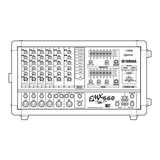
POWERED MIXER
Owner's Manual
EEEngine
LEVEL
1
2
3
4
5
HIGH
HIGH
HIGH
HIGH
HIGH
–15
+15
–15
–15
+15
–15
+15
–15
+15
MID
MID
MID
MID
MID
–15
+15
–15
+15
–15
+15
–15
+15
–15
LOW
LOW
LOW
LOW
LOW
–15
+15
–15
+15
–15
+15
–15
+15
–15
MONI
MONI
MONI
MONI
MONI
0
10
0
10
0
10
0
10
0
EFFECT
EFFECT
EFFECT
EFFECT
EFFECT
0
10
0
10
0
10
0
10
0
LEVEL
LEVEL
LEVEL
LEVEL
0
10
0
10
0
10
0
10
0
PAD
PAD
PAD
PAD
1
2
3
4
5
1
Hi-Z
Hi-Z
Hi-Z
Hi-Z
LINE
Lo-Z
Lo-Z
Lo-Z
Lo-Z
MIC
6
HIGH
VO. ECHO 1
+12
•
6
•
VO. ECHO 2
0
+15
–15
+15
•
6
MID
•
–12
VO. REV. 1
125
250
500
+15
–15
+15
VO. REV. 2
LOW
HALL. 1
0
10
+15
–15
+15
EFFECT RTN
MONI
HALL. 2
MONITOR
ROOM
10
0
10
+12
•
EFFECT
6
PLATE
•
0
•
6
•
10
0
10
–12
LEVEL
ON
125
250
500
10
0
10
0
10
0
EFFECT RTN
AUX IN
DIGITAL
6
EFFECT
2
1
2
INST
EFFECT OUT
MIC
FOOT SW
SEE REAR PANEL CAUTION
+6
POWER
+12
•
6
+3
•
0
0
•
ON
6
–5
PHANTOM
OFF
•
–12
–10
1k
2k
4k
8k
0
10
0
10
TAPE IN
MASTER
2 AMPs
300W
300W
+6
+12
1
2
•
6
+3
•
0
0
LIMITER
•
6
–5
•
–12
–10
MAIN
BRIDGE
1k
2k
4k
8k
MAIN
MAIN
MAIN
MONITOR
10
0
10
0
10
TAPE IN
MASTER
MAIN
POWER AMP
MONITOR
TAPE
REC
IN
OUT
1
1
AUX IN
MAIN
2
2
EEEngine
INPUT
OUTPUT
E
Advertisement
Table of Contents

Related Manuals for Yamaha EMX660


Summary of Contents for Yamaha EMX660
- Page 1 POWERED MIXER Owner’s Manual EEEngine HIGH HIGH HIGH HIGH HIGH HIGH VO. ECHO 1 POWER • • • • VO. ECHO 2 –15 –15 –15 –15 –15 –15 • • –5 PHANTOM • • –12 –12 –10 VO. REV. 1 –15 –15 –15...
- Page 2 300 ohm ribbon lead, change the lead-in to coaxial type cable. If these corrective measures do not produce satisfactory results, please contact the local retailer authorized to distribute this type of product. If you can not locate the appropriate retailer, please contact Yamaha Corporation of America, Electronic Service Division, 6600 Orangethorpe Ave, Buena Park, CA 90620 The above statements apply ONLY to those products distributed by Yamaha Corporation of America or its subsidiaries.
- Page 3 This should be: 30 cm at the sides, 30 cm behind, and 40 cm above. For normal ventilation during use, remove the rear of the rack or open a ventilation hole. If the airflow is not adequate, the unit will heat up inside and may cause a fire. EMX660—Owner’s Manual...
- Page 4 EMX660—Owner’s Manual...
-
Page 5: Table Of Contents
Thank you for purchasing the Yamaha EMX660 Powered Mixer. The EMX660 has the following features. In order to take full advantage of the EMX660 and enjoy long and trouble-free performance, please read this owner’s manual carefully, and keep it in a safe place for future reference. -
Page 6: Front And Rear Panel
The base frequency (or center frequency), range of boost or cut, and equalizer type of each band are as follows. HIGH: 12 kHz ±15 dB shelving type MID: 2.5 kHz ±15 dB peaking type LOW: 80 Hz ±15 dB shelving type EMX660—Owner’s Manual... -
Page 7: Digital Effect Section
This indicator allows you to monitor the level of the signal which is output from the MONITOR jack (input/output panel 6). Note: To avoid distortion, adjust the MASTER control (A) so that the 0 indicator lights occa- sionally. EMX660—Owner’s Manual... -
Page 8: Main Section
MONITOR bus signal is output from the control (G) so that the 0 indicator lights occa- POWER AMP 2 A/B jacks. Only the MASTER sionally. controls in the MAIN and MONITOR sections G, A are both effective. EMX660—Owner’s Manual... - Page 9 POWER PHANTOM POWER indicator This indicator will light when the power of the EMX660 is turned on. PHANTOM switch This switch turns the phantom power supply on/ off for the Lo-Z input jacks of channels 1–4 and MIC input jacks of channels 5–6.
-
Page 10: Input/Output Panel
Foot switch jack (FOOT SW) must be connected to the Hi-Z or LINE jacks if A separately sold Yamaha FC5 foot switch can be the PHANTOM switch (control panel L) is on. connected to this jack. If a foot switch is con- nected to this jack, you can use your foot to switch the built-in digital effect on/off. - Page 11 External output jacks (REC OUT/MONI- TOR/MAIN) These are output jacks which send line level sig- nals from the EMX660 to external devices. A stereo recording device such as a cassette deck, DAT or MD recorder can be connected to the...
-
Page 12: Rear Panel
At this time, use the power amp select switch Power switch on the control panel to select a signal sent to the This switch turns the power of the EMX660 on/ correct jacks. off. When the power amp select switch is set to... -
Page 13: Installation/Connection
Installation/Connection Installation/Connection Installation The EMX660 uses a forced cooling system with intake on the bottom of the rear panel and exhaust on the top of the rear panel to avoid blocking the heated air flow. Front 30cm or less Exhaust... -
Page 14: Example Connections
EMX660, in practice, only one effects processor, internal or external, will be used at a time, so the footswitch is not required when using external effects. -
Page 15: Basic Operation
Basic Operation Basic Operation This section explains basic operation of the EMX660. Connecting microphones Monitoring and instruments By connecting a powered monitor speaker to the MONITOR OUTPUT, you can create a monitor Before connecting mics or instruments, mix independent of the MAIN mix, since the... -
Page 16: Example Setups
This section provides some ways in which the EMX660 can be used, and explains connections and operation. As a conference PA system/installed sound system Here is an example of using the EMX660 as a conference PA system or as an installed sound system. Main Speakers... -
Page 17: As A Band Pa
As a band PA Here is an example of using the EMX660 as a small PA for a band. In this example, the monitor speakers are being sent a mix that is independent of the MAIN speaker mix. An external effect such as delay or reverb is also being used. -
Page 18: Using An External Effect
This allows the effect. you to create a mix that is independent of the MAIN section. Use the graphic equalizers and MASTER controls of the MAIN/MONITOR sections to adjust the overall volume and tone. EMX660—Owner’s Manual... -
Page 19: Troubleshooting
(page 11) and change the connections so that the impedance is correct. Connections between devices have Inspect the connections, and correct any faulty con- come loose. nections. Other The device may have malfunctioned. Please con- Other tact your dealer. EMX660—Owner’s Manual... -
Page 20: Specifications
USA and Canada 120 V AC 60 Hz Power requirement Europe 230 V AC 50 Hz Other 240 V AC 50 Hz Power consumption 250 W Dimensions (WxHxD) 497 275 275 mm Weight 17 kg • 0 dB=0.775 Vrms EMX660—Owner’s Manual... -
Page 21: Input Specifications
• All output jacks are unbalanced. • 0 dB=0.775 Vrms, 0 dBV=1 Vrms. Specifications are subject to change without prior notice. For European Model Purchaser/User Information specified in EN55103-1 and EN55103-2. Inrush Current: 56A Conformed Environment: E1, E2, E3 and E4 EMX660—Owner’s Manual... -
Page 22: Dimensions
Specifications Dimensions W:497 (67.5) 45.5 45.5 57.5 D:275 Unit mm EMX660—Owner’s Manual... -
Page 23: Block And Level Diagram
Block and Level diagram Block and Level diagram 8kHz 8kHz 4kHz 4kHz 2kHz 2kHz 1kHz 1kHz 500Hz 500Hz 250Hz 250Hz 125Hz 125Hz MONITOR MONITOR EFFECT EFFECT MAIN MAIN EFFECT DIGITAL EMX660—Owner’s Manual... - Page 24 YAMAHA CORPORATION V529000 R0 1 IP 24 Pro Audio Division, #18/3 P.O. Box 3, Hamamatsu, 430-8651, Japan NP Printed in Taiwan...