Yamaha RIVAGE PM Series Owner's Manual
Dsp engine for digital mixing system
Hide thumbs
Also See for RIVAGE PM Series:
- Supplemental manual (31 pages) ,
- Supplemental manual (14 pages)
Table of Contents
Advertisement
Quick Links
Advertisement
Table of Contents

Related Manuals for Yamaha RIVAGE PM Series


Summary of Contents for Yamaha RIVAGE PM Series
- Page 1 DSP ENGINE DSP-RX-EX DSP-RX Owner’s Manual SIGNAL PROCESSOR...
- Page 2 ATTENTION RISQUE DE CHOC ELECTRIQUE-NE PAS OUVRIR CAUTION: ATTENTION : TO REDUCE THE RISK OF ELECTRIC SHOCK, POUR RÉDUIRE LES RISQUES D'ÉLECTROCUTION, NE PAS RETIRER DO NOT REMOVE COVER (OR BACK). LE CAPOT (OU LE DOS). NE CONTIENT PAS DE PIÈCES NÉCESSITANT NO USER-SERVICEABLE PARTS INSIDE.
- Page 3 Yamaha Corporation of America or its subsidiaries. of other electronic devices. Compliance with FCC regulations does * This applies only to products distributed by Yamaha Corporation of America. (class B) COMPLIANCE INFORMATION STATEMENT (Supplier’s declaration of conformity procedure)
-
Page 4: Precautions
If you intend to use the product in an area other than in the one you purchased, the included power cord may not be compatible. Please check with your Yamaha dealer. • Check the electric plug periodically and remove any dirt or dust which may have accumulated on it. - Page 5 When the backup battery needs to be replaced, “Low Battery” or “No Battery” will appear on the display. In this case, contact your Yamaha dealer and have qualified Yamaha service personnel replace the backup battery. DSP-RX(-EX) Owner’s Manual...
- Page 6 (weee_eu_en_02) disposing of this product, please contact the appropriate local authorities. Yamaha cannot be held responsible for damage caused by improper use or modifications to the product, or data that is lost or destroyed. The model number, serial number, power requirements, etc., may be found on or near the name plate, which is at the top of the unit.
-
Page 7: Table Of Contents
Contents PRECAUTIONS............4 Introduction.............8 Accessories................8 Optional Items ..............8 Firmware Updates ..............8 Precautions for Rack Mounting..........8 Recessed Installation ............8 Part Names & Functions ..........9 Front Panel ................9 Rear Panel ................10 Euroblock Plug Connection ..........12 Installing and Removing Optional Cards ....13 Installing a Mini-YGDAI Card..........13 Removing the Mini-YGDAI Card.........13 Installing an HY Card ............14... -
Page 8: Introduction
Introduction Rack Mounting This unit is rated for operation at ambient temperatures Thank you for choosing the Yamaha DSP-RX(-EX) DSP ranging from 0 to 40 degrees Celsius. If you mount this engine unit. unit along with other DSP unit(s) or other device(s) in an In order to take full advantage of the DSP-RX(-EX)’s... -
Page 9: Part Names & Functions
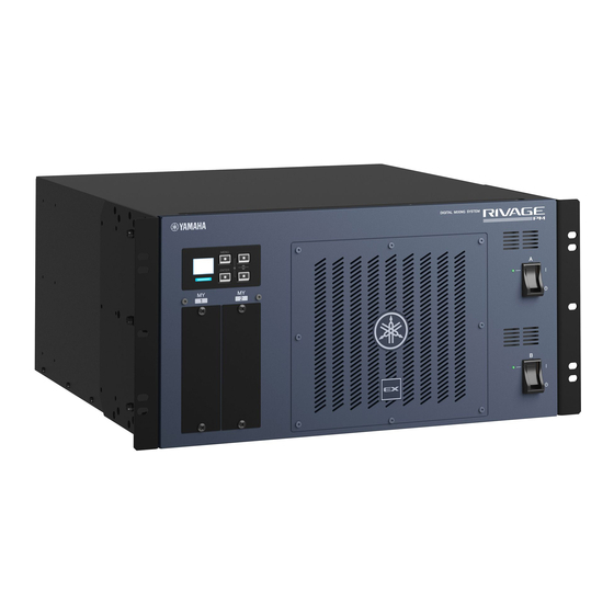
Part Names & Functions Front Panel * This EX logo badge is attached on the DSP-RX-EX. The DSP-RX does not feature this badge. 1 LCD UnitMode Toggles between Default mode and Theatre Indicates the setting parameters for the unit. mode. F/W Ver. -
Page 10: Rear Panel
Rear Panel & #$ % 1 Vent 3 MIDI OUT/IN jacks This unit is equipped with cooling fans. These vents These jacks are used to transmit/receive MIDI let warm air out from the unit. Please make sure that messages to/from external MIDI devices. you do not block the vents with any object. - Page 11 This unit supports the following HY cards. If the indicator does not turn off, please contact your • Slot 1-2: HY256-TL, HY256-TL-SMF Yamaha dealer. • Slot 1-4: HY144-D, HY144-D-SRC, HY128-MD For the latest information, refer to the Yamaha Pro Audio global website. http://www.yamahaproaudio.com/ DSP-RX(-EX) Owner’s Manual...
-
Page 12: Euroblock Plug Connection
Euroblock Plug Connection Insert the cables. You must use the supplied Euroblock plug to connect to the FAULT OUTPUT connector. Preparation (Cable preparation) Approx. 7mm Securely tighten the terminal screws. Approx. 20mm Pull the cables (not too strongly) to confirm that they •... -
Page 13: Installing And Removing Optional Cards
Installing a Mini-YGDAI Card Before you install the card, you must check the Yamaha Pro Audio global website to see whether the DSP-RX(-EX) supports that card, and to verify the number of other Yamaha cards or third-party cards that can be used in conjunction with this card. -
Page 14: Installing An Hy Card
Installing an HY Card Push the card all the way into the slot so that the connector at the end of the card is correctly inserted into the connector inside the slot. Make sure that both power indicators are off. Caution Installing or removing a card while the power is on may lead to component failure or electric shock. -
Page 15: Removing The Hy Card
Removing the HY Card Power Supply Make sure that both power indicators are off. Connecting the AC Power Caution Cord Installing or removing a card while the power is on may lead to component failure or electric shock. Turn off both power switches A and B on the unit. -
Page 16: About Dek-Dsp-Rx
Input channel ❍ Make sure that the power switches are turned ON. ❍ Make sure that the AC power cords are connected. ➥ If the power still does not turn on, contact your Yamaha Plug-in dealer. Please consult your Yamaha dealer for more information The unit is not receiving an audio input signal. -
Page 17: On-Screen Messages
An error message for caution or attention will be displayed on the front panel LCD, and will be indicated via the color indicator. Additional messages might be added due to functional improvements. For the latest error message list, refer to the RIVAGE PM series Operation Manual posted on the Yamaha Pro Audio global website. http://www.yamahaproaudio.com Error messages indicating caution Repair might be required. - Page 18 OP: Output Power, IP: Input Power have the unit checked by an authorized technician, although the problem will not affect operation of the unit. Please contact your Yamaha dealer. Ethernet cable is not connected properly. A number sign (#) indicates the error description.
-
Page 19: Specifications
Specifications General Specifications Sampling frequency Conditions Min. Typ. Max. Unit External clock Frequency range Fs= 44.1 kHz, 48 kHz, 88.2 kHz, 96 kHz –1000 — +1000 Jitter of PLL WORD CLOCK IN Fs= 44.1 kHz, 48 kHz, 88.2 kHz, — —... - Page 20 Control I/O characteristics Balanced / Terminal Format Level Connector Unbalanced MIDI MIDI – DIN 5pin – MIDI – DIN 5pin – TC IN SMPTE 0.3 Vpp (Min.) / XLR-3-31 type SMPTE Balanced 10.0 Vpp (Max.), 10 kΩ WORD CLOCK – TTL/75 Ω...
-
Page 21: Pin Assignment Table
Approximate Munsell value of exterior color: N5 Unit: mm * The contents of this manual apply to the latest specifications as of the publishing date. To obtain the latest manual, access the Yamaha website then download the manual file. DSP-RX(-EX) Owner’s Manual... -
Page 22: Index
Index Brightns (Brightness) ........9 On-screen Messages........17 Optional Cards ..........13 Card Installing Rack Mounting ..........8 HY Card..........14 Recessed Installation......... 8 Mini-YGDAI card.......13 Removing HY Card..........15 Settings Mini-YGDAI card.......13 Brightns (Brightness) ......... 9 Connecting the AC Power Cord ....15 Contrast............ - Page 23 Yamaha Music Gulf FZE Tel: +356-2133-2093 JAFZA-16, Office 512, P.O.Box 17328, Jebel Ali FZE, Dubai, UAE Tel: +971-4-801-1500 PA54 Head Office/Manufacturer: Yamaha Corporation 10-1, Nakazawa-cho, Naka-ku, Hamamatsu, 430-8650, Japan (For European Countries) Importer: Yamaha Music Europe GmbH Siemensstrasse 22-34, 25462 Rellingen, Germany...
- Page 24 Yamaha Pro Audio global website http://www.yamahaproaudio.com/ Yamaha Downloads https://download.yamaha.com/ Manual Development Group © 2020 Yamaha Corporation Published 05/2020 IPES-B0 VEE1300...