Table of Contents
Advertisement
INSTALLATION AND
OPERATION MANUAL
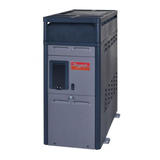
Atmospheric
Above-Ground
Pool & Spa Heater
(Chauffe-Piscine)
Models 106 and 156
English/French
WARNING:
If
the
A
instructions are not followed exactly, a fire or
explosion may result causing property damage,
personal injury or death.
FOR YOUR SAFETY: Do not store or use
gasoline or other flammable vapors and
liquids or other combustible materials in the
vicinity of this or any other appliance. To do
so may result in an explosion or fire.
WHAT TO DO IF YOU SMELL GAS:
• Do not try to light any appliance.
• Do not touch any electrical switch; do not
use any phone in your building.
• Immediately call your gas supplier from a
neighbor's phone. Follow the gas suppli-
er's instructions.
• If you cannot reach your gas supplier, call
the fire department.
Installation and service must be performed by
a qualified installer, service agency or the gas
.
supplier
This manual should be maintained in legible condition and kept adjacent to the heater or in a safe place for future
reference.
CATALOG NO. 6100.62G
information
in
these
Effective: 06-08-18
AVERTISSEMENT:
A
suivre les instructions données dans cette notice
pour réduire au minimum le risque d'incendie ou
d'explosion ou pour éviter tout dommage matériel,
toute blessure ou la mort.
Ne pas entreposer ni utiliser d'essence ou ni
d'autres vapeurs ou liquides inflammables à
proximité de cet appareil ou de tout autre appareil.
CE FAIRE SI VOUS SENTEZ UNE ODEUR
DE GAZ:
•
Ne pas tenter d'allumer d'appareil.
•
Ne touchez á aucun interrupteur; ne pas
vous servir des téléphones se trouvant dans
la bâtiment.
•
Appelez immédiatement votre fournisseur
de gaz depuis un voisin. Suivre les instruc-
tions du fournisseur.
•
Si vous ne pouvez rejoindere le fournisseur,
appelez le service es incendies.
L'installation et l'entretien doivent être assurés
par un installeur qualifié ou par le fournisseur
de gaz.
Replaces: 04-15-18
Assurez-vous
de
bien
P/N 241519 Rev. 8
Advertisement
Table of Contents

Related Manuals for Raypak 106


Summary of Contents for Raypak 106
- Page 1 INSTALLATION AND OPERATION MANUAL Atmospheric Above-Ground Pool & Spa Heater (Chauffe-Piscine) Models 106 and 156 English/French WARNING: information these AVERTISSEMENT: Assurez-vous bien instructions are not followed exactly, a fire or suivre les instructions données dans cette notice explosion may result causing property damage, pour réduire au minimum le risque d’incendie ou...
- Page 2 Revision 8 reflects the following changes: Manual updated to the new format style. Removed California Proposition 65 warning on pages 4 and 7. Replaced "analog/electronic" with 106/156 on section 3.3.1, page 6. Replaced "analog/digital" with 106/156 on section 5.5.3, page 21.
-
Page 3: Table Of Contents
8. TROUBLESHOOTING ..........27 4.3. Base Installation ............8 8.1. Mechanical ............. 27 4.4. Outdoor Installation ..........10 8.2. P-106 Control Logic Flow Chart ....... 28 4.5. Indoor Installation ..........10 8.3. P-156 Control Logic Flow Chart ....... 29 4.6. Combustion and Ventilation Air 9. -
Page 4: Warnings
1. WARNINGS 1.1. Pay Attention to These Terms Indicates the presence of immediate hazards which will cause severe personal injury, death or DANGER substantial property damage if ignored. Indicates the presence of hazards or unsafe practices which could cause severe personal injury, WARNING death or substantial property damage if ignored. -
Page 5: Water Chemistry
2. WATER CHEMISTRY • Automatic chemical dosing devices and salt chlorinators are usually more efficient in heated NOTE: Corrosive water voids all warranties. water, unless controlled, they can lead to excessive chlorine level which can damage your heater. Chemical imbalance can cause severe damage to your •... -
Page 6: Before Installation
Ambient Temperature Rating of help from a qualified installer, service technician, or the Components gas supplier. 106 Heater -40°F to +175°F (-40°C to 79°C) 3.2. Water Temperature Safety 156 Heater -32°F to +175°F (-35°C to 79°C) Elevated water temperature can be hazardous. The 3.3.2. -
Page 7: General Information
3.4. General Information Shipping Weight Gas Conn. Water Conn. Model No. Input Std. Heater (NPT) (NPT) Drafthood Assembly w/ Stackless Top 105,000 BTU/hr. 85 lbs. (30.75 KW) (38.6 kg) 1/2" 1-1/2" or 2" 14 lbs. (1.27 cm) (3.8 cm or 5 cm) (6.35 kg) 150,000 BTU/hr. -
Page 8: Clearances
4.2. Clearances Distance Description Location in. (mm) Back 9 (229) AVERTISSEMENT: Cet appareil doit être installé Right 9 (229) conformément au National Fuel gas Code ANSI Z223.1, et a. 3-1/2" (89 mm) thick Left 9 (229) aux exigences de l’autorité competente. masonry walls without Vent 5 (127) - Page 9 Amp Draw 120 Volt 240 Volt Figure 4. Heater Dimensions Figure 5. Florida Building Code Tie-Down Method...
-
Page 10: Outdoor Installation
WARNING: Do not install within 3' (0.9 m) of a heat not come standard with the heater. Use part number 014718 for the 106 and 014719 for the 156. pump or an outdoor condensing unit. Strong air intake from this type of equipment can disturb the combustion process and cause damage or personal injury. -
Page 11: Combustion And Ventilation Air (Indoor Units Only)
See Vent Piping section for details. Minimum allowable 4.6.1. Vent Piping space is shown on the rating plate. Follow the installation instructions provided with the Indoor Drafthood Kit for Appliance Categories installation. Heaters are divided into four categories based on the NOTE: For Canada, indoor installation is restricted to pressure produced in the exhaust and the likelihood of an enclosure that is not occupied and does not directly... -
Page 12: Gas Connections
HEATER JACKET VENT CAP 8' (2.4 m) GAS INLET OR LESS MANUAL SHUT-OFF VALVE (Field supplied) GAS VALVE 24" MIN (610 mm) 24" MIN FINISH FLANGE (610 mm) 5' (1.5 m) UNION VENT PIPE (Field supplied) SEDIMENT TRAP (Field supplied) DRAFTHOOD Figure 9. - Page 13 Electronic Ignition Gas Valves 4.7.5. Flow Rates Model Minimum Maximum 106/156 20 GPM (75 L) 70 GPM (265 L) Table H. Water Flow Rates When the flow rates exceed the maximum 70 GPM (265 L), an external auxiliary bypass valve is required. See section "External Auxiliary Bypass Valve"...
- Page 14 4.7.7. Internal Automatic Bypass Valve 4.7.10. Pressure Relief Valve Installation A built-in automatic bypass valve is provided in the In/Out To conform to local building codes, it may be necessary header. The internal bypass valve automatically responds to install a pressure relief valve. A 3/4” (1.9 cm) pressure to changes in water pressure in the piping system.
-
Page 15: Electrical Connections
4.8. Electrical Connections 4.9. 240 Volt Installation Instructions Be sure that electrical service to the heater has proper CAUTION: This heater has provisions to be connected overload fuse or circuit breaker protection, wire size and to an alternate supply source. To reduce the risk of electric connections which comply with all applicable codes. -
Page 16: Controls
5. CONTROLS 5.1. P-106 Control Adjustments The P-106 has an analog control system. The pool or spa water temperature is controlled by the thermostat on the upper front panel of the heater. The control center contains an On/Off toggle switch and a thermostat. The switch functions as a means for turning the heater On or Off. -
Page 17: P-156 Control Adjustments
5.2. P-156 Control Adjustments 5.3. P-156 Thermostat Operation The P-156 has a digital control system. The pool heater (chauffe-piscine) touchpad, located on the upper front panel of the heater, allows the user to select either POOL or SPA operation, and to adjust the setpoint temperature. The LCD display window indicates the mode (OFF, SPA, POOL) and the actual water temperature. - Page 18 Figure 25. Run Time Indicator Both the POOL and SPA setpoints will revert to 65°F (18°C) and both POOL and SPA maximum temperature settings Press the DOWN button. The Fault History displays up to will be 104°F (40°C). The Control Lockout PIN will be ten faults in memory.
-
Page 19: Status And Diagnostics
The following conditions are displayed only while there is NOTE: Both the POOL and SPA setpoints will revert back to a demand for heat present. 65°F (18°C) and the POOL and SPA maximum temperature settings will be 104°F (40°C). These setpoints will need to Display Condition be readjusted to desired settings. -
Page 20: Remote Control Wiring
5.4.1. Remote Control Installation and 5.4.3. Activating the Remote Operation To activate or deactivate the remote function, follow these steps: CAUTION: Before installing remote controls to the 1. Press and hold the UP and DOWN arrow buttons for P-156 heaters, read the following: The digital thermostat 3 to 5 seconds. - Page 21 NOTE: The remote wires must be connected to the 7-pin connector before the connector is plugged into the board. 5.5.1. 2-Wire Remote Control (On-Off) This application assumes that only one heating function (pool or spa) is required. 1. Turn on power to the heater. 2.
-
Page 22: Post Start-Up Inspection
On P-106 heaters, splice into the red/white wire to connect 5.6.1. Cold Weather Operation the time clock. For P-156 heaters the fireman’s switch connection is located on the 14-pin header connected to Moderate Climate the digital control board. Splice into the red wire jumper Heater operation can continue during short-term cold tagged “Where necessary add “Fireman’s”... -
Page 23: Wiring Diagrams
6. WIRING DIAGRAMS Figure 35. P-106 Heater Wiring Figure 36. P-156 Heater Wiring... -
Page 24: Maintenance
3. Turn pump off and on several times. Heater should 7. MAINTENANCE shut off immediately. If it does not, repeat the above steps. The following preventative maintenance is to be NOTE: If heater is installed outside of the limits shown, a performed one month after start-up and semi-annually higher pressure rated 11 psi (76 kPa) switch may be used. - Page 25 12. Reverse above procedure to reinstall. 7.1.4. Flame Roll-Out Safety Switch Heaters are equipped with a thermal cutoff device to prevent flame roll-out in the event the heat exchanger becomes blocked. This is a “single-use” type fusible link or thermal fuse, that must be replaced when disabled by an over-temperature condition, caused by excessive restriction in the heat exchanger flue passage, roll-out, high winds, etc.
- Page 26 Another method is to remove the heat exchanger, ream 7.1.10. Heat Exchanger Removal tubes and immerse heat exchanger in non-inhibited de- 1. Shut water, gas and electricity off, close valves and scale solvent for severe scale build-up. relieve pressure, then remove relief valve. Remove 7.1.12.
-
Page 27: Troubleshooting
8. TROUBLESHOOTING 8.1. Mechanical IMPORTANT NOTICE: These instructions are intended for the use of qualified personnel who are specifically trained and experienced in the installation of this type of heating equipment and related system components. Installation and service personnel may be required by some states to be licensed. Persons not qualified shall not attempt to install this equipment nor attempt repairs according to these instructions. -
Page 28: P-106 Control Logic Flow Chart
8.2. P-106 Control Logic Flow Chart START Turn knob to a desired temperature zone. The home circuit breaker may have tripped. Check and reset if necessary. Turn switch on. After six (6) seconds, Is there power to the heater? does the pilot spark? 1. -
Page 29: P-156 Control Logic Flow Chart
8.3. P-156 Control Logic Flow Chart Power On • Check On/Off switch (under lid on control panel) Is the water • Check for 120/240 volts to the transformer temperature displayed? (time clock, circuit breaker, wire connections) • Check for 24 volts to Circuit Board (P6 connector) “Remote”... -
Page 30: Illustrated Parts List
9. ILLUSTRATED PARTS LIST 10-S 10-C 12-M 11-M 10-M... - Page 31 14-H 13-H 12-H 15-H 10-H (OPTIONAL) 11-H 16-H (OPTIONAL) 17-H...
- Page 32 Natural 1.30mm (0-4,999 ft) Propane 1.84mm (0-1,999 ft) *FOR ALTITUDES ABOVE THOSE LISTED, CONSULT THE FACTORY.
- Page 33 014894F 014895F Jacket Right 014896F 014897F Jacket Upper Front 014898F 014898F Jacket Lower Rear 014899F 014899F Flue Collector 014900F 014901F Door Panel Raypak 014902F 014902F Rheem 014903F 014903F Ruud 014902F 014902F Access Panels 014904F 014904F Control Panel Analog 014905F Digital...
- Page 34 NOTES...
- Page 35 NOTES...
- Page 36 Raypak, Inc., 2151 Eastman Avenue, Oxnard, CA 93030 (805) 278-5300 Fax (805) 278-5468 Litho in U.S.A.