Dell EMC PowerEdge MX7000 Installation And Service Manual
Hide thumbs
Also See for EMC PowerEdge MX7000:
- Manual (48 pages) ,
- Quick start manual (9 pages) ,
- Field service manual (89 pages)

Related Manuals for Dell EMC PowerEdge MX7000


Summary of Contents for Dell EMC PowerEdge MX7000
- Page 1 Dell EMC PowerEdge MX7000 Enclosure Installation and Service Manual Regulatory Model: E44S Series Regulatory Type: E44S001...
- Page 2 A WARNING indicates a potential for property damage, personal injury, or death. © 2018 Dell Inc. or its subsidiaries. All rights reserved. Dell, EMC, and other trademarks are trademarks of Dell Inc. or its subsidiaries. Other trademarks may be trademarks of their respective owners.
-
Page 3: Table Of Contents
Contents 1 About this document............................6 2 Next Generation Modular overview........................7 PowerEdge MX architecture overview.......................... 10 3 Enclosure overview............................11 Front view of the enclosure.............................12 Control panel................................13 PSU indicators................................16 Fan module indicator codes............................17 Back view of the enclosure............................. 18 Management module indicator codes........................ - Page 4 Removing a power supply unit..........................36 Installing a power supply unit............................ 37 Acoustic baffle..................................38 Removing the air baffle............................. 38 Installing the air baffle..............................39 Fabrics and modules................................40 Removing a blank from Fabric A or B slot......................40 Installing a blank in Fabric A or B slot........................41 Removing a module from Fabric A or B slot......................
- Page 5 Contacting Dell EMC...............................65 Documentation feedback..............................65 Accessing system information by using QRL....................... 65 Quick Resource Locator for PowerEdge MX7000 enclosure................66 Receiving automated support with SupportAssist ..................... 66 8 Documentation resources..........................67 Contents...
-
Page 6: About This Document
About this document This document provides an overview about the PowerEdge MX7000, information about installing and replacing components, technical specifications, and guidelines to follow while installing components. About this document... -
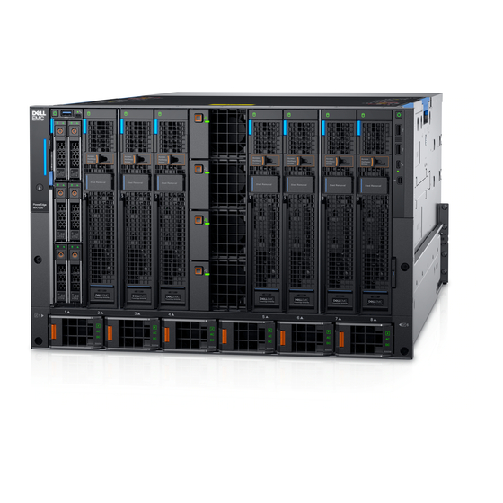
Page 7: Next Generation Modular Overview
Next Generation Modular overview Figure 1. Next Generation Modular - Front view • Compute sleds - MX740c, and MX840c • Storage sled - MX5016s Next Generation Modular overview... - Page 8 Figure 2. Next Generation Modular - Back view The Dell EMC PowerEdge MX7000 enclosure supports the following sleds and I/O modules: • I/O modules - – Dell EMC Power Networking MX7116n – Dell EMC Power Networking MX9116n Fabric Switching Engine –...
- Page 9 Dell EMC PowerEdge MX 10GBASE-T Ethernet Pass-Through Module The Dell 10 Gb Ethernet pass-through module II supports 10 Gb connections. It provides a direct connection between the optional internal Ethernet mezzanine card in the sled and an external Ethernet device. The Ethernet pass-through modules are hot-swappable.
-
Page 10: Poweredge Mx Architecture Overview
An industry-leading fabric, system thermal architecture, mechanical design, and control algorithms for dense configurations with future compatibility • A hardened design to protect, detect, and recover underlying infrastructure from cyber attacks For more information about these modules and sleds, see their documents which are available at Dell.com/poweredgemanuals. Next Generation Modular overview... -
Page 11: Enclosure Overview
Enclosure overview The Dell EMC PowerEdge MX7000 is the next-generation M1000e follow-on chassis and a revolutionary architecture set to be the future foundation of modular architecture. The PowerEdge MX7000 enclosure is a 7U chassis that supports: • Up to eight standard height, single-width sleds, or four standard height, double-width sleds. -
Page 12: Front View Of The Enclosure
Front view of the enclosure Figure 3. Front view of the enclosure Left control panel Single-width compute sled Sled blank Front fan (4) Double-width compute sled Single-width storage sled Right control panel Information tag Power supply unit (6) Enclosure overview... -
Page 13: Control Panel
Control panel Left control panel Figure 4. Left control panel - Status LED Table 1. Left control panel - LED indicator description Indicator Description Status System health Blinks amber for 2 seconds and is OFF for 1 second when the chassis health has degraded. By default, the LED is unlit. - Page 14 Figure 5. Left control panel - LCD options Table 2. Left control panel - LCD panel description Indicator Description Status LCD with Quick LCD enabled with Quick Sync module Sync LCD without Quick LCD without Quick Sync module Sync System ID indicator This option is a button/indicator on the LCD panel to identify the chassis, or choose specific sleds to on LCD panel identify.
- Page 15 Indicator Description Status System ID Indicator status Description System ID indicator/ Blinking blue System ID is active. Identification Blinking amber Chassis alerts are present. indicator Error indicator The error indicator is displayed on the LCD when there are any critical/warning alerts on the enclosure.
-
Page 16: Psu Indicators
PSU indicators Figure 7. PSU indicators PSU health indicator AC supply status indicator DC output status indicator Table 3. PSU health indicator codes PSU health indicator Indicator state PSU functioning normally Green PSU faulty Blinking amber PSU mismatch ON for 1 second, and then 5 blinks and OFF (non-repeating cycle). Table 4. -
Page 17: Fan Module Indicator Codes
Fan module indicator codes Figure 8. Front fan module Figure 9. Rear fan module Table 6. Fan module indicator codes Fan indicators Indicator state Fan functioning normally - Front/ Rear Solid green Fan failure Blinks amber 2 seconds and 1 second OFF NOTE: When the chassis is powered off with the AC connection that is powered on, only the rear fans are powered off. -
Page 18: Back View Of The Enclosure
Back view of the enclosure Figure 10. Back view of the enclosure Slot for Fabric A1 Slot for Fabric A2 Rear fans (5) Slot for Fabric B1 Slot for Fabric B2 Slot for Fabric C2 Power cable connection status LED C22 Power inlet connectors (6) Management Module 2 Management Module 1... -
Page 19: Management Module Indicator Codes
Service Tag. Alternatively, the information may be on a sticker on the back of the system chassis. The mini Enterprise Service Tag (EST) is found on the back of the system chassis. Dell uses this information to route support calls to the appropriate personnel. - Page 20 Figure 12. Locating the information tag of your system Information tag (Top view) MAC address and secure password label NOTE: If you have opted for default access to the management module, the default password is available on the Information tag. This label is blank, if you have not opted for secure default access, then the default username and password are root and calvin.
-
Page 21: Initial System Setup And Configuration
Complete the following steps to set up your enclosure: Unpack the enclosure. Install the enclosure into the rack. For more information, see the Rail Installation Guide at Dell.com/poweredgemanuals. Connect the peripherals to the enclosure. Connect the enclosure to its electrical outlet. -
Page 22: Log In To The Management Module
NOTE: Ensure that you change the default username and password after setting up the management module IP address. For more information about logging in to the management module, see the Dell EMC OpenManage Enterprise Modular User's Guide at Dell.com/manuals. Methods of setting up and configuring the IP address for the management... -
Page 23: Downloading Drivers And Firmware
> OpenManage Enterprise Modular Downloading drivers and firmware Dell recommends that you download and install the latest BIOS, drivers, and systems management firmware on your system. Prerequisite Ensure that you clear the web browser cache before downloading the drivers and firmware. -
Page 24: Configuring The Static Ip Address Using The Lcd
Steps To set up the IP address out-of-the-box: Select the Language, and tap Next. The select Home Page screen is displayed. Tap Preview, to view the default Home page view. The available Home page views are: • Main Menu • IP Settings •... -
Page 25: Installing And Removing System Components
Damage due to servicing that is not authorized by Dell is not covered by your warranty. Read and follow the safety instructions that are shipped with your product. -
Page 26: Hot Plug And Non-Hot Plug Devices
Hot plug and Non-hot plug devices Table 9. Hot plug devices Hot plug devices Non-hot plug devices Cooling fans Main distribution board Power supply units Vertical power distribution board Management services modules Rear fan board Fabric A/ B/ C input output modules Left and right control panels Sleds NOTE:... -
Page 27: Installing A Sled Blank
Figure 13. Removing a sled blank Next step Install a sled sled blank. Installing a sled blank Prerequisite Follow the safety guidelines listed in Safety instructions. Steps Align the sled blank with the bay in the enclosure. Insert and push the sled blank, until it locks into place. NOTE: Install two sled blanks when a double-width sled is removed. -
Page 28: Removing A Compute Or Storage Sled From The Enclosure
Figure 14. Installing a sled blank Removing a compute or storage sled from the enclosure Prerequisites Follow the safety guidelines listed in Safety instructions. Power off the sled. CAUTION: Ensure the compute sleds mapped to the storage sleds are powered off. CAUTION: Remove the storage sled only when the hard drive LED is off. - Page 29 To release the sled release lever, push the blue release button on the sled. Hold the sled release lever, pull the sled out of the enclosure. NOTE: Ensure that you install a sled blank if you are removing the sled permanently. CAUTION: Operating the enclosure without a blank, for an extended time can result in overheating.
-
Page 30: Installing A Compute Or Storage Sled Into The Enclosure
Figure 16. Removing a single-width compute sled from the enclosure Install the I/O connector cover on the sled. Next step Install a sled a sled blank. Installing a compute or storage sled into the enclosure Prerequisites Follow the safety guidelines listed in Safety instructions. - Page 31 Figure 17. Removing the I/O cover Hold and align the sled with the bay in the enclosure. Push the sled into the bay in the enclosure. NOTE: The procedure to install a single-width and double-width sled is the same. Close the release lever to lock the sled in place. Figure 18.
-
Page 32: Cooling Fan Modules
Figure 19. Installing a storage sled into the enclosure Next step Power on the sled. Cooling fan modules NOTE: The system must be populated with the full set of fans to support the airflow requirements of the chassis. Removing a front fan module Steps Press the release button to release the fan module. -
Page 33: Installing A Front Fan Module
Figure 20. Removing a front fan module Next step Install a front fan module. Installing a front fan module Insert the fan module into the fan bay. Push the fan module into the fan bay, until it locks into place. NOTE: Ensure that the green LED on the fan module is illuminated, indicating that the module is functioning properly. -
Page 34: Removing A Rear Fan Module
Figure 21. Installing the front fan module Removing a rear fan module Steps Press the release button to release the fan module. Hold and pull the fan module out of the fan bay. Installing and removing system components... -
Page 35: Installing A Rear Fan Module
Figure 22. Removing a rear fan module Next step Install the rear fan module. Installing a rear fan module Insert the fan module into the fan bay. Push the fan module into the fan bay, until it locks into place. NOTE: Ensure that the green LED on the fan module is illuminated, indicating that the module is functioning properly. -
Page 36: Power Supply Units
Figure 23. Installing a rear fan module Power supply units Removing a power supply unit Prerequisites CAUTION: At least two power supply units (PSUs) must be installed for the enclosure to function properly. Follow the safety guidelines listed in Safety instructions. -
Page 37: Installing A Power Supply Unit
Figure 24. Removing a power supply unit Next step Install a PSU or a PSU blank. Installing a power supply unit Prerequisite Follow the safety guidelines listed in Safety instructions. Steps Push the PSU into the enclosure until it is seated firmly. Close the PSU release lever to secure the PSU in the bay. -
Page 38: Acoustic Baffle
Figure 25. Installing a power supply unit Next step Connect the power cable to the corresponding PSU connector on the rear of the chassis. NOTE: When installing or hot swapping a PSU, wait for 15 seconds for the system to recognize the PSU and determine its status. -
Page 39: Installing The Air Baffle
Figure 26. Removing the air baffle Installing the air baffle Align the air baffle with the enclosure. Push the air baffle, until it locks into place. Installing and removing system components... -
Page 40: Fabrics And Modules
Figure 27. Installing the air baffle Fabrics and modules There are several connections on the Main Distribution Board to enable communication between the IOMs. Between each pair of IOMs (C1 and C2), there is a link for intermodule communication. This link is referred as Fabric-V in the schematics. This link supports a x1 connection with each lane operating up to 10 Gbps per direction. -
Page 41: Installing A Blank In Fabric A Or B Slot
Figure 28. Removing a blank from Fabric A or B slot Next step Install a module in the Fabric A or B slot blank. Installing a blank in Fabric A or B slot Prerequisites Follow the safety guidelines listed in Safety instructions. -
Page 42: Removing A Module From Fabric A Or B Slot
Figure 29. Installing a blank in Fabric A or B slot Removing a module from Fabric A or B slot Prerequisites Follow the safety guidelines listed in Safety instructions. Disconnect the cables that are connected to the modules. Steps Press the orange release button on the module to open the release levers. Hold the release levers, and pull the module out of the enclosure. -
Page 43: Installing A Module In Fabric A Or B Slot
Figure 30. Removing a module from Fabric A or B slot Next step Install a module into Fabric A or B slot blank. Installing a module in Fabric A or B slot Prerequisite Follow the safety guidelines listed in Safety instructions. -
Page 44: Removing A Blank From Fabric C Slot
Figure 31. Installing a module into Fabric A or B slot Next step Connect the cables to the module. Removing a blank from Fabric C slot Steps Press the release button to release the blank. Pull the blank out of the enclosure. NOTE: To maintain proper airflow, ensure that the blanks are installed if the IOMs is not installed. -
Page 45: Installing A Blank In Fabric C Slot
Figure 32. Removing a blank from Fabric C slot Next step Install the module in the Fabric C slot blank. Installing a blank in Fabric C slot Prerequisites Follow the safety guidelines listed in Safety instructions. Remove the module from Fabric C slot. -
Page 46: Removing A Module From Fabric C Slot
Figure 33. Installing a blank in Fabric C slot Removing a module from Fabric C slot Prerequisites Follow the safety guidelines listed in Safety instructions. Disconnect the cables that are connected to the modules. Steps Press the orange release button on the module to open the release lever. Hold the release lever, and pull the I/O module out of the enclosure. -
Page 47: Installing A Module Into Fabric C Slot
Figure 34. Removing a module from Fabric C slot Next steps Install a module into Fabric C Install a blank. Connect the cables to the module. Installing a module into Fabric C slot Prerequisite Follow the safety guidelines listed in Safety instructions. -
Page 48: Removing A Management Module Blank
Figure 35. Installing a module into Fabric C slot Next step Connect the cables to the module. NOTE: Ensure that the SAS IOMs have the same firmware version. The OpenManage-Enterprise modular User interface allows OpenManage Enterprise-Modular User's Guide . you to view the firmware details. For more information, see Removing a management module blank Steps Press the release button to release the blank. -
Page 49: Installing A Management Module Blank
Figure 36. Removing a management module blank Next step Install the management module Install a blank. Installing a management module blank Prerequisites Follow the safety guidelines listed in Safety instructions. Remove the management module. Steps Align and insert the blank in the empty slot. Insert and push the blank until it locks into place. -
Page 50: Removing A Management Module
Figure 37. Installing a management module blank Removing a management module Prerequisites Follow the safety guidelines listed in Safety instructions. Disconnect the cables that are connected to the modules. Steps Press the orange release button on the module to open the release lever. Hold the release lever, and pull the management module out of the enclosure. - Page 51 Damage due to servicing that is not authorized by Dell is not covered by your warranty. Read and follow the safety instructions that are shipped with your product.
-
Page 52: Installing A Management Module
Figure 39. Management Module jumper Replace the Management Module. The existing Management Module passwords are not disabled (erased) until the system boots with the jumper on pins 1 and 2. However, before you assign a new system and/or setup Management Module password, you must move the jumper back to pins 2 and NOTE: If you assign a new system and/or setup Management Module password with the jumper on pins 1 and 2, the system disables the new Management Module password the next time that it boots. - Page 53 Figure 40. Installing a management module Next step Reconnect the network cables to the management module. Installing and removing system components...
-
Page 54: Technical Specifications
Technical specifications The technical and environmental specifications of your system are outlined in this section. Topics: • Component guidelines • Chassis dimensions • Chassis weight • Fan specifications • PSU specifications • Ports and connectors specifications • PowerEdge MX modules ports and connectors •... -
Page 55: Psu Redundancy And Population Rules
Category Maximum population Storage Sled Up to seven Storage sleds can be populated in the enclosure. NOTE: One compute node must be present and it must be mapped to a storage node. One Fabric-C SAS IOM must be present and powered ON. I/O Module Only Brocade and SAS IOM are supported in Fabric-C. -
Page 56: Chassis Dimensions
PSU count Population order 1, 4, 2, 5, 3 1, 4, 2, 5, 3, 6 Chassis dimensions Figure 41. Dimensions of the PowerEdge MX7000 Table 12. Dimensions of the PowerEdge MX7000 Description Dimension 482 mm (18.98 inches) 445 mm (17.52 inches) 307.4 mm (12.11 inches) 816.6 mm (32.15 inches) 811.6 mm (31.96 inches) -
Page 57: Chassis Weight
Chassis weight Table 13. Chassis weight Enclosure Minimum weight Maximum weight (fully populated) PowerEdge MX7000 82 kg (180 lbs) 182 kg (400 lbs) Fan specifications The PowerEdge MX7000 enclosure supports four front accessible hot-swap cooling fans and five rear accessible hot-swap cooling fans. The cooling fan assembly ensures that the key components of the server such as the sleds, Fabrics, and I/O modules get adequate air circulation to keep them cool. -
Page 58: Ports And Connectors Specifications
Ports and connectors specifications USB ports The PowerEdge MX7000 enclosure supports two Type A, USB 2.0 ports on the front panel. Mini DisplayPort The PowerEdge MX7000 enclosure supports one Mini DisplayPort (mini DP) on the front panel. NOTE: You must use a mini DP dongle to connect the enclosure to a VGA display. PowerEdge MX modules ports and connectors PowerEdge MX740c Table 16. -
Page 59: Poweredge Mx7116N
PowerEdge MX7116n Table 18. PowerEdge MX7116n externally accessible connectors Connector Description Externally accessible connectors • 2 QSFP28-DD connections to the MX7116n PowerEdge MX9116n Table 19. PowerEdge MX9116n externally accessible connectors Connector Description Externally accessible connectors • 12 QSFP28-DD ports that can be configured as: –... -
Page 60: Poweredge Mxg610S
PowerEdge MXG610s Table 21. PowerEdge MXG610s externally accessible connectors Connector Description USB port One micro USB 2.0-compliant port on the front of the sled. Fibre Channel transceiver 16 external ports supporting 8/ 16/ 32 Gbps speeds using 8 SFPs and 2 QSFPs. PowerEdge MX 10GBASE-T Ethernet Pass-Through Module Table 22. -
Page 61: Environmental Specifications
NOTE: 1920 x 1080 and 1920 x 1200 resolutions are only supported in reduced blanking mode. Environmental specifications NOTE: For additional information about environmental measurements for specific system configurations, see Dell.com/ poweredgemanuals. Table 25. Temperature specifications Temperature Specifications Storage –40°C to 65°C (–40°F to 149°F) 20°C/h (36°F/h) -
Page 62: Standard Operating Temperature
Table 30. Operating temperature derating specification Operating temperature Specifications derating Up to 35°C (95°F) Maximum temperature reduces by 1°C/300 m (1°F/547 ft), above 950 m (3,117 ft). 35°C to 40°C (95°F to Maximum temperature reduces by 1°C/175 m (1°F/319 ft), above 950 m (3,117 ft). 104°F) 40°C to 45°C (104°F to Maximum temperature reduces by 1°C/125 m (1°F/228 ft), above 950 m (3,117 ft). -
Page 63: Particulate And Gaseous Contamination Specifications
For more information about the expanded operating temperature restrictions, see the Installation and Service Manual for the PowerEdge MX sleds at Dell.com/poweredgemanuals. Table 33. Expanded operating temperature restrictions System C40E45 Dell EMC PowerEdge MX7000 No restrictions No restrictions No restrictions including the fans, Management... - Page 64 Table 35. Gaseous contamination specifications Gaseous Specifications contamination Copper Coupon <300 Å/month per Class G1 defines that, ANSI/ISA71.04-1985. Corrosion Silver Coupon Corrosion <200 Å/month defines that, AHSRAE TC9.9. NOTE: Maximum corrosive contaminant levels measured at ≤50% relative humidity. Technical specifications...
-
Page 65: Getting Help
The Contact Technical Support page is displayed with details to call, chat, or e-mail the Dell EMC Global Technical Support team. Documentation feedback You can rate the documentation or write your feedback on any of our Dell EMC documentation pages and click Send Feedback to send your feedback. Accessing system information by using QRL You can use the Quick Resource Locator (QRL) located on the information tag in the front of the MX7000, to access the information about the Dell EMC PowerEdge MX7000. -
Page 66: Quick Resource Locator For Poweredge Mx7000 Enclosure
Receiving automated support with SupportAssist Dell EMC SupportAssist is an optional Dell EMC Services offering that automates technical support for your Dell EMC server, storage, and networking devices. By installing and setting up a SupportAssist application in your IT environment, you can receive the following benefits: •... -
Page 67: Documentation Resources
Configuring your system For information about the iDRAC features, Dell.com/poweredgemanuals configuring and logging in to iDRAC, and managing your system remotely, see the Integrated Dell Remote Access Controller User's Guide. For information about understanding Remote Access Controller Admin (RACADM) subcommands and supported RACADM interfaces, see the RACADM CLI Guide for iDRAC. - Page 68 Dell.com/operatingsystemmanuals system, see the operating system documentation. Managing your system For information about systems management Dell.com/poweredgemanuals software offered by Dell, see the Dell OpenManage Systems Management Overview Guide. For information about setting up, using, and Dell.com/openmanagemanuals > OpenManage troubleshooting OpenManage, see the Dell Server Administrator OpenManage Server Administrator User’s Guide.