
Related Manuals for Dell External M1000e t


Summary of Contents for Dell External M1000e t
- Page 1 Dell PowerEdge M1000e Enclosure Owner's Manual Regulatory Model: BMX01...
-
Page 2: Notes, Cautions, And Warnings
CAUTION: A CAUTION indicates either potential damage to hardware or loss of data and tells you how to avoid the problem. WARNING: A WARNING indicates a potential for property damage, personal injury, or death. © 2012 Dell Inc. Trademarks used in this text: Dell , the Dell logo, Dell Boomi , Dell Precision , OptiPlex... -
Page 3: Table Of Contents
Contents Notes, Cautions, and Warnings....................2 1 About Your System........................7 ..............................7 System Overview ..........................9 System Control-Panel Features ................................10 LCD Module ............................11 LCD Module Features .........................12 Using The LCD Module Menus ..............................12 Configuration Wizard ..............................13 Back-Panel Features ..........................14 Power Supply Indicators .............................16 Fan Module Indicators ....................17 Avocent iKVM Analog Switch Module (Optional) - Page 4 ....................35 General I/O Module Configuration Guidelines ................................35 Fabric A ................................36 Fabric B ................................36 Fabric C ......36 Port Auto-Disablement in Quad-Port Network Daughter Card (Dell PowerEdge M710HD Only) ..............................37 Mezzanine Cards ...........................37 PowerEdge M610x Only ............................37 Full-Height Blades ............................37 Half-Height Blades .....................39...
- Page 5 .................58 Dell PowerConnect M6348 1 Gb Ethernet Switch I/O Module .................59 Dell PowerConnect M6220 Ethernet Switch I/O Module ...............60 Dell PowerConnect M8024 10 Gb Ethernet Switch I/O Module ..........................61 Dell 8/4 Gbps FC SAN Module ........................62 Brocade M5424 FC8 I/O Module ..........................64...
- Page 6 Troubleshooting Enclosure Components ........................94 Troubleshooting A Wet Enclosure ......................94 Troubleshooting Power Supply Modules ..........................95 Troubleshooting Fan Modules .........................95 Troubleshooting The iKVM Module ...........................95 Troubleshooting I/O Modules 6 Technical Specifications......................97 ............................97 Enclosure Specifications ............................98 I/O Module Specifications 7 Getting Help..........................103 ..............................103 Contacting Dell...
-
Page 7: About Your System
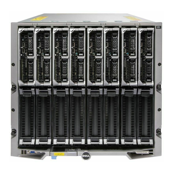
About Your System System Overview Your system can include up to 16 half-height blades (server modules), eight full-height blades, eight sleeves with quarter-height blades, or a mix of the three blade types. To function as a system, a blade or sleeve is inserted into an enclosure (chassis) that supports power supplies, fan modules, a Chassis Management Controller (CMC) module, and at least one I/O module for external network connectivity. - Page 8 Figure 2. Blade Numbering – Full Height Blades Figure 3. Blade Numbering – Quarter Height Blades...
-
Page 9: System Control-Panel Features
Figure 4. Blade Numbering – Mixed Full-Height, Half-Height, and Quarter-Height Blades System Control-Panel Features Figure 5. Control-Panel Features 1. USB port (mouse only) 2. USB port (keyboard only) 3. video connector... -
Page 10: Lcd Module
4. system power button 5. system power indicator Control Panel Description Features USB ports for Icon keyboard and mouse Description USB port 1 connects to the mouse and USB port 2 connects to the keyboard. NOTE: The USB ports are functional if an optional iKVM module is installed and front panel ports are enabled (default setting) in the CMC interface. -
Page 11: Lcd Module Features
Figure 6. LCD Display 1. LCD screen 2. scroll buttons (4) 3. selection ("check") button LCD Module Features The primary function of the LCD module is to provide real-time information on the health and status of the modules in the enclosure. -
Page 12: Using The Lcd Module Menus
DHCP to a static address by either running the LCD configuration wizard, or by using a management station and CLI commands. For more information, see the CMC documentation at support.dell.com/manuals. To set up a network using the LCD configuration wizard: If you have not already done so, press the chassis power button to turn it on. -
Page 13: Back-Panel Features
DNS settings If required, configure the iDRAC network settings. For more information about iDRAC, see the iDRAC User’s Guide at support.dell.com/manuals. NOTE: The configuration wizard automatically configures each blade’s iDRAC internal network interface if you do not choose to manually configure the iDRAC settings. -
Page 14: Power Supply Indicators
Figure 8. Back-Panel Module Bay Numbering 1. CMC 1 (primary CMC module) 2. A1 B1 C1 (left I/O modules) 3. iKVM (iKVM module) 4. C2 B2 A2 (right I/O modules) 5. CMC 2 (secondary CMC module) Power Supply Indicators NOTE: The AC power supplies must be connected to a Power Distribution Unit (PDU), not directly to an electrical outlet. - Page 15 Figure 9. Power Supply Indicators 1. DC power output indicator 2. power supply fault indicator 3. AC power indicator The power supply indicators provide the following information: Indicator Description DC power output Icon indicator Description Green indicates that the power supply is operational and providing DC power to the system.
-
Page 16: Fan Module Indicators
Fan Module Indicators Figure 10. Fan Module Indicators 1. fan power indicator 2. fan fault indicator The indicators provide the following information: Indicator Description Fan power indicator Solid Green The fan is receiving DC power and working properly. The fan has failed. Fan fault indicator Amber The fan is in a fault condition. -
Page 17: Avocent Ikvm Analog Switch Module (Optional)
Avocent iKVM Analog Switch Module (Optional) Figure 11. Avocent iKVM Switch Module 1. status/identification indicator 4. Analog Console Interface (ACI) port (for tiering connection only) 2. power indicator 5. activity indicator 3. link indicator 6. USB connectors (2) for keyboard and mouse CAUTION: Do not connect the ACI port to a 7. -
Page 18: Avocent Analog Ikvm Switch Module Features
NOTE: The iKVM USB ports do not support storage devices. • RJ-45 Analog Console Interface (ACI) port for tiering with Dell and Avocent analog KVM and KVM over IP switches with Analog Rack Interface (ARI) ports. NOTE: Although the ACI port is an RJ-45 connector and uses Cat5 (or better) cabling, it is not an Ethernet network interface port. -
Page 19: Cmc Module
CMC Module Figure 12. CMC Module Features Ethernet connector Gb1 Ethernet connector STK ("stack") - used for daisy- chaining CMCs in separate enclosures link indicator activity indicator DB-9 serial connector for local configuration optional secondary CMC (CMC 2) optional iKVM module primary CMC (CMC 1) blue status/identification indicator power indicator... -
Page 20: Cmc Fail-Safe Mode
– User access security NOTE: It is recommended that you isolate chassis management from the data network. Dell cannot support or guarantee uptime of a chassis that is improperly integrated into your environment. Due to the potential of traffic on the data network, the management interfaces on the internal management network can be saturated by traffic intended for servers. -
Page 21: Daisy-Chain Cmc Network Connection
See the latest CMC User's Guide at support.dell.com/manuals for complete instructions on how to set up and operate the CMC module. The following figure illustrates the arrangement of cables for four daisy-chained chassis, each with active and standby... -
Page 22: System Messages
Figure 13. CMC Daisy-Chaining 1. management network 2. secondary CMC 3. primary CMC System Messages System messages related to the blades in the enclosure may appear on the monitor screen to notify you of a possible problem with a blade. For a detailed listing of these error messages, including possible causes and solutions, see the blade documentation. - Page 23 Dell systems management application documentation provides information about installing and using the systems management software. • For the full name of an abbreviation or acronym used in this document, see the Glossary at support.dell.com/ manuals. • Any media that ships with your system that provides documentation and tools for configuring and managing your system, including those pertaining to the operating system, system management software, system updates, and system components that you purchased with your system.
-
Page 25: Initial System Configuration
Reinstall the blades and power supplies after you install the chassis in the rack. Unpack the enclosure and install it in a rack. Getting Started Guide and Rack Installation Guide at support.dell.com/manuals. For more information, see the CAUTION: Do not turn on the blades (server modules) until you have configured the switch modules. -
Page 26: Configuring The Cmc Using The Lcd Configuration Wizard
Configuring The CMC Using The LCD Configuration Wizard When you first boot your system, the screen on the LCD module directs you to configure the CMC network settings. NOTE: The option to configure the enclosure using the LCD configuration wizard is only available until the CMC default password is changed or when the LCD configuration wizard is complete. -
Page 27: Logging In To The Cmc Using The Web-Based Interface
The new network settings are activated in a few seconds after configuring the network. Logging In To The CMC Using The Web-Based Interface Open a supported web browser window. For current information on supported web browsers, see the CMC User’s Guide at support.dell.com/manuals. Log in to the CMC. –... -
Page 28: Adding And Managing Cmc Users
To refresh the contents of the Users page, click Refresh. To print the contents of the Users page, click Print. Select general settings for the users. For details on user groups and privileges, see the CMC User’s Guide at support.dell.com/manuals. Assign the user to a CMC user group. -
Page 29: Setting The First Boot Device For Servers
You can use the web-based and RACADM interfaces to manage and configure power controls on the CMC, as outlined in the following sections. For more information on the various power management options, see the CMC User’s Guide at support.dell.com/manuals. The CMC’s power management service optimizes power consumption for the entire chassis (the chassis, servers, I/O modules, iKVM, CMC, and PSUs) and re-allocates power to different modules based on the demand. -
Page 30: Downloading The Cmc Firmware
CMC in the left slot as primary. Downloading The CMC Firmware Before beginning the firmware update, download the latest firmware version from support.dell.com, and save it to your local system. The following software components are included with your CMC firmware package: •... -
Page 31: Configuring The Optional Ikvm Switch Module
Tiering The Avocent iKVM Switch From A Digital KVM Switch The iKVM module may also be tiered from a digital KVM switch such as the Dell 2161DS-2 or 4161DS, or a supported Avocent digital KVM switch. Many switches may be tiered without the need for a Server Interface Pod (SIP). -
Page 32: Configuring The Analog Switch
• Dell PowerConnect 180AS, 2160AS (version 1.0.3.2 or later) or Avocent Autoview 2020, 2030 (version 1.6.0.4 or later): Seamless tiering using ACI port and Cat 5 cable • Avocent Autoview 1400, 1500, 2000, 1415, 1515, 2015u: Avocent USB SIP (DSRIQ-USB) required with Cat 5 cable... -
Page 33: Resynchronizing The Server List At The Remote Client Workstation
NOTE: Server names and slot numbers are assigned by the CMC. NOTE: If you have enabled access to the CMC though the iKVM, an additional option, Dell CMC Console, is displayed. -
Page 34: Flexaddress Plus
USB "Memory Card Reader". You must then unlock the SD card before inserting it into the CMC. For more information on the FlexAddress feature, see the following resources: • The CMC Secure Digital (SD) Card Technical Specification document at support.dell.com/manuals • The Help link in the CMC web interface •... -
Page 35: Configuring The I/O Modules
Configuring The I/O Modules Network Information You can configure your I/O switch modules using: • CMC web-based interface. NOTE: The default IP address for the CMC is 192.168.0.120. • CMC CLI using serial console redirection. • Direct access to the I/O module serial port (if supported). •... -
Page 36: Fabric B
Fabric C mezzanine card location. Modules designed for Fabric A may also be installed in the Fabric C slots. Port Auto-Disablement in Quad-Port Network Daughter Card (Dell PowerEdge M710HD Only) Systems installed with quad-port Network Daughter Card support a Port Auto-Disablement feature. This feature disables the third (NIC3) and fourth (NIC4) ports of a quad-port network daughter card during system boot, if the corresponding I/O module installed in the chassis Fabric A slots does not support quad-port mapping. -
Page 37: Mezzanine Cards
IOM Slot A1 IOM Slot A2 NIC3 and NIC4 (Enabled/ Port Auto-Disablement Disabled) Dual Port Dual Port Disabled Active Dual Port Quad or Greater Port Enabled Inactive Quad or Greater Port Empty Enabled Inactive Quad or Greater Port Dual Port Enabled Inactive Quad or Greater Port... - Page 38 Table 2. Supported I/O Module Configurations Fabric A Fabric B Mezzanine Fabric C Mezzanine I/O Bay A1, A2 I/O Bay B1, B2 I/O Bay C1, C2 Card Card Standard None None Ethernet None None Integrated LOM switch module or pass- through module Standard...
-
Page 39: I/O Module Port Mapping-Full-Height Blades
Fabric A Fabric B Mezzanine Fabric C Mezzanine I/O Bay A1, A2 I/O Bay B1, B2 I/O Bay C1, C2 Card Card or pass- through module Standard Infiniband mezzanine Ethernet mezzanine Ethernet Infiniband Ethernet switch Integrated LOM card card switch module switch module module or or pass-... - Page 40 n+8 . Mezzanine card 3, connection 2 connects • Mezzanine card 3, connection 1 connects to I/O module C1, port n+8 . to I/O module C2 port n+8 . Mezzanine card 4, connection 2 connects • Mezzanine card 4, connection 1 connects to I/O module B1, port n+8 .
- Page 41 Figure 14. Example of PowerEdge M610x Port Mapping – Blade 2 Table 4. I/O Module Port Assignments - Full-Height Blades (not applicable for PowerEdge M610x) Blade 1 I/O Module Mezz1_Fab_C Port 1 Port 1 Mezz2_Fab_B Port 1 Port 1 Mezz3_Fab_C Port 9 Port 9 Mezz4_Fab_B...
- Page 42 Blade 2 I/O Module Mezz3_Fab_C Port 10 Port 10 Mezz4_Fab_B Port 10 Port 10 Blade 3 I/O Module Mezz1_Fab_C Port 3 Port 3 Mezz2_Fab_B Port 3 Port 3 Mezz3_Fab_C Port 11 Port 11 Mezz4_Fab_B Port 11 Port 11 Blade 4 I/O Module Mezz1_Fab_C Port 4...
- Page 43 Blade 7 I/O Module Mezz3_Fab_C Port 15 Port 15 Mezz4_Fab_B Port 15 Port 15 Blade 8 I/O Module Mezz1_Fab_C Port 8 Port 8 Mezz2_Fab_B Port 8 Port 8 Mezz3_Fab_C Port 16 Port 16 Mezz4_Fab_B Port 16 Port 16 The following figure shows the port connections for a full-height blade in bay 3 with four mezzanine cards. Figure 15.
-
Page 44: Quad-Port Mezzanine Cards
Quadport Capable Hardware for the M1000e NOTE: For a detailed mapping of each PowerEdge system, see Modular Chassis at support.dell.com/manuals. Table 5. Example of I/O Module Port Assignments - PowerEdge M610x in Slot 2 Blade n and Blade (n + 8) -
Page 45: I/O Module Port Mapping─Half-Height Blades
Blade n and Blade (n + 8) I/O Module NOTE: n denotes a variable value from 1 to 8. (n+24) Mezz_FAB_C_Blade n Port +8_Port4 NOTE: Even though PowerEdge M610x is a full blade system, only two mezzanine card slots (MEZZ1_Fab_C1 and MEZZ2_FAB_B1) in the expansion bay are available for use. -
Page 46: Dual-Port Mezzanine Cards
• Integrated LOM2 connection 2 connects to I/O module A2, port 21. Dual-Port Mezzanine Cards For a half-height blade in bay n and I/O module A2, port n . • The integrated NIC connects to I/O module A1, port • Mezzanine card B connects to I/O module B1, port n and I/O module B2, port n . -
Page 47: Quad-Port Mezzanine Cards
NOTE: For a detailed mapping of each PowerEdge system, see Quadport Capable Hardware For the M1000e Modular Chassis at support.dell.com/manuals. Table 8. Example of I/O Module Port Assignments - PowerEdge M610x in Slot 2 Blade I/O Module... -
Page 48: I/O Modules-Switches
Blade I/O Module Mezz_FAB_B_Blade Port n_Port1 Mezz_FAB_B_Blade Port n_Port2 (n+16) Mezz_FAB_B_Blade Port n_Port3 (n+16) Mezz_FAB_B_Blade Port n_Port4 Mezz_FAB_C_Blade Port n_Port1 Mezz_FAB_C_Blade Port n_Port2 (n+16) Mezz_FAB_C_Blade Port n_Port3 (n+16) Mezz_FAB_C_Blade Port n_Port4 I/O Modules—Switches Configuring A Switch Module Network Ethernet Port Using The Web-Based Interface You can use the CMC web-based interface to configure an I/O module’s Ethernet port. -
Page 49: Brocade M6505 16 Gbps Fc San I/O Module
After all I/O modules have been configured and connected, the enclosure’s blades can be inserted and booted with full network communication. Brocade M6505 16 Gbps FC SAN I/O Module The Brocade M6505 16 Gbps FC I/O module includes eight external fibre channel ports, 16 internal ports, and one serial port with an RJ-45 connector. -
Page 50: Dell Poweredge M I/O Aggregator Switch
The PowerEdge I/O Aggregator is a layer 2 switch blade with two fixed 40 GbE ports on the base module and provides support for two optional plug-in modules. The Aggregator runs the Dell Force10 Operating System (FTOS) and autoconfigures as an unmanaged switch with bridging and multiplexing features. -
Page 51: Dell Force10 Mxl 10/40 Gbe Switch
Two-port 40 GbE QSFP+ module for 10 GbE SFP+ connections using 4 x 10 GbE breakout cables. For additional information about the PowerEdge M I/O Aggregator switch module, see the documentation that shipped with the module. Figure 19. Dell PowerEdge M I/O Aggregator Switch 1. expansion slot 1 5. USB console port 2. -
Page 52: Mellanox M4001F/M4001Q/M4001T Infiniband Switch I/O Module
Two-port 40 GbE QSFP+ module for 10 GbE SFP+ connections For additional information about the Force10 MXL 10/40 GbE switch module, see the documentation that shipped with the module. Figure 20. Dell Force10 MXL 10/40 GbE Switch I/O Module 1. expansion slots (8) 5. status/identification indicator 2. -
Page 53: Dell Powerconnect Kr 8024-K Switch
4. module status indicator 5. power indicator Dell PowerConnect KR 8024-k Switch The PowerConnect KR M8024-k switch provides 16 internal 10 GbE ports, four external 10 GbE SFP+ ports, and one 10 GbE expansion slot for 10 GbE external uplinks. The expansion slot on the front panel can support the following modules: •... -
Page 54: Dell Powerconnect M8428-K 10 Gb Converged Network Switch
5. expansion slot Dell PowerConnect M8428-k 10 Gb Converged Network Switch The Dell PowerConnect M8428-k 10 Gb Converged Network switch module supports FCoE protocols and allows fibre channel traffic to travel over 10 Gbps Enhanced Ethernet (DCB) networks. This module consists of: •... -
Page 55: Mellanox M2401G Ddr Infiniband Switch I/O Module
Figure 23. Dell PowerConnect M8428-k 10 Gb Converged Network Switch 1. LED status indicators (12) 5. power indicator 2. serial port (RJ-45 connector) 6. 8 Gb fibre channel ports (ports 25–27 and port 0) 3. module status indicator 7. 10 GbE ports (ports 17–24) 4. -
Page 56: Mellanox M3601Q Qdr Infiniband Switch I/O Module
Figure 24. Mellanox M2401G DDR Infiniband Switch Module 1. Infiniband ports (8) 2. port link status indicators (8) 3. port activity indicators (8) 4. module diagnostic power indicator 5. module status indicator Mellanox M3601Q QDR Infiniband Switch I/O Module The Mellanox M3601Q QDR Infiniband switch I/O module includes 32 4x QDR Infiniband ports. Of these, 16 ports are external uplink ports, while 16 internal ports provide connectivity to the blades in the enclosure. -
Page 57: Cisco Catalyst Ethernet Switch I/O Modules
Figure 25. Mellanox M3601Q QDR Infiniband Switch I/O Module 1. Infiniband ports (16) 2. port link status indicators (16) 3. port activity indicators (16) 4. module diagnostic power indicator 5. module status indicator Cisco Catalyst Ethernet Switch I/O Modules Your system supports three Cisco Catalyst Blade Switch (CBS) versions: •... -
Page 58: Dell Powerconnect M6348 1 Gb Ethernet Switch I/O Module
4. Cisco status indicators 5. mode button Dell PowerConnect M6348 1 Gb Ethernet Switch I/O Module PowerConnect M6348 is a hot-swappable 48-port 1 Gb Ethernet switch. While 16 ports are external uplink ports, the remaining 32 internal ports provide connectivity to the blades within the enclosure with a maximum bandwidth of 1 Gbps each. -
Page 59: Dell Powerconnect M6220 Ethernet Switch I/O Module
3. CX4 stacking connectors (2) 4. console management connector Dell PowerConnect M6220 Ethernet Switch I/O Module The PowerConnect M6220 Ethernet switch module includes four external 10/100/1000 Mbps Ethernet connectors and one USB type A form factor serial connector. Two option bays support the following modules: •... -
Page 60: Dell Powerconnect M8024 10 Gb Ethernet Switch I/O Module
3. serial connector (USB type-A form factor) 4. power indicator 5. status/identification indicator Dell PowerConnect M8024 10 Gb Ethernet Switch I/O Module The PowerConnect M8024 switch module incorporates two optional bays that support the following modules: • A 10 Gb Ethernet module with four optical SFP+ connectors •... -
Page 61: Dell 8/4 Gbps Fc San Module
Dell 8/4 Gbps FC SAN Module The Dell 8/4 Gbps FC SAN module includes 24 total autosensing fibre channel ports (12 ports are enabled in the standard configuration and 12 additional ports may be enabled as an optional upgrade) and one serial port with an RJ-45 connector. -
Page 62: Brocade M5424 Fc8 I/O Module
Figure 30. Dell 8/4 Gbps FC SAN Module 1. fibre channel ports (8) 5. module status indicator 2. fibre channel port status indicators (8) 6. power indicator 3. fibre channel port speed indicators (8) 7. status/identification indicator 4. serial port (RJ-45 connector) - Page 63 Figure 31. Brocade M5424 FC8 I/O Module 1. fibre channel ports (8) 5. module status indicator 2. fibre channel port status indicators (8) 6. power indicator 3. fibre channel port speed indicators (8) 7. status/identification indicator 4. serial port (RJ-45 connector) The following are the I/O module indicators: Fibre channel Indicator...
-
Page 64: I/O Modules-Pass-Through
Fault condition in module I/O Modules—Pass-Through Dell 4 Gbps Fibre Channel Pass-Through Module The 4 Gbps fibre channel pass-through module provides a bypass connection between a fibre channel mezzanine card in the blade and optical transceivers for direct connection into a fibre channel switch or a storage array. The 16 pass- through ports on this module can negotiate speeds of 1 Gbps, 2 Gbps, or 4 Gbps. - Page 65 Figure 32. 4 Gbps Fibre Channel Pass-Through Module 1. SFP fibre channel connectors (16) 2. fibre channel green/amber indicators (two per port) 3. power indicator 4. status/identification indicator The following are the fibre channel pass-through indicators: Power Indicator Off: Power to the module is off Green: Module has power Status/ Blue off: Secondary module in a stack...
-
Page 66: Dell 10 Gbe Kr Pass-Through I/O Module
SFP+ (short reach or long reach) and direct-attached copper (DCA) SFP+ modules. The Ethernet pass-through module is hot-swappable and may be installed in Fabric A, B, or C. The pass-through module does not support 1G mezzanine or network daughter cards in blades. Figure 33. Dell 10 GbE KR Pass-Through I/O Module... -
Page 67: Dell 10 Gb Ethernet Pass-Through Module Ii
Dell 10 Gb Ethernet Pass-Through Module II The Dell 10 Gb Ethernet pass-through module II supports 10 Gb connections and provides a direct connection between the optional internal Ethernet mezzanine card in the blade and an external Ethernet device. The Ethernet pass-through modules are hot-swappable and may be installed in Fabric B or Fabric C. -
Page 68: 10/100/1000 Mb Ethernet Pass-Through I/O Module
10/100/1000 Mb Ethernet Pass-Through I/O Module The Ethernet pass-through module supports 10/100/1000 Mb connections and provides a direct connection between the optional internal Ethernet mezzanine card in the blade and an external Ethernet device. The Ethernet pass-through modules are hot-swappable and may be installed in any of the three Fabrics. NOTE: To ensure proper functionality, use only the SFP transceivers provided with this module. -
Page 69: Installing Enclosure Components
Damage due to servicing that is not authorized by Dell is not covered by your warranty. Read and follow the safety instructions that came with the product. - Page 70 Figure 36. Removing and Installing a Half-Height Blade 1. blade handle 2. release button 3. blade 4. guide rail on enclosure 5. guide rail on blade (or blade blank) Figure 37. Removing and Installing a Full-Height Blade 1. blade handle...
-
Page 71: Installing A Blade
Slide the blade into the enclosure until the handle engages and locks the blade in place. Power Supply Modules The Dell PowerEdge M1000e enclosure supports up to six hot-swappable power supply modules, accessible from the enclosure back panel. NOTE: The power supply modules have internal fans that provide thermal cooling to these modules. A power supply module must be replaced if an internal fan failure occurs. - Page 72 Damage due to servicing that is not authorized by Dell is not covered by your warranty. Read and follow the safety instructions that came with the product.
- Page 73 Damage due to servicing that is not authorized by Dell is not covered by your warranty. Read and follow the safety instructions that came with the product.
-
Page 74: Dc Power Supply Modules
DC power and to safety grounds. Do not attempt connecting to DC power or installing grounds yourself. All electrical wiring must comply with applicable local or national codes and practices. Damage due to servicing that is not authorized by Dell is not covered by your warranty. Read and follow all safety instructions that came with the product. - Page 75 DC power and to safety grounds. Do not attempt connecting to DC power or installing grounds yourself. All electrical wiring must comply with applicable local or national codes and practices. Damage due to servicing that is not authorized by Dell is not covered by your warranty. Read and follow all safety instructions that came with the product.
- Page 76 DC power and to safety grounds. Do not attempt connecting to DC power or installing grounds yourself. All electrical wiring must comply with applicable local or national codes and practices. Damage due to servicing that is not authorized by Dell is not covered by your warranty. Read and follow all safety instructions that came with the product.
- Page 77 WARNING: Reversing polarity when connecting DC power wires can permanently damage the power supply or the system. Insert the copper ends into the mating connectors and tighten the captive screws at the top of the mating connector using a #2 Phillips screwdriver. The captive screws must be torqued to 16 in lbs (1.8 N-m) to ensure proper cable retention.
- Page 78 DC power and to safety grounds. Do not attempt connecting to DC power or installing grounds yourself. All electrical wiring must comply with applicable local or national codes and practices. Damage due to servicing that is not authorized by Dell is not covered by your warranty. Read and follow all safety instructions that came with the product.
- Page 79 DC power and to safety grounds. Do not attempt connecting to DC power or installing grounds yourself. All electrical wiring must comply with applicable local or national codes and practices. Damage due to servicing that is not authorized by Dell is not covered by your warranty. Read and follow all safety instructions that came with the product.
-
Page 80: Fan Modules
Damage due to servicing that is not authorized by Dell is not covered by your warranty. Read and follow the safety instructions that came with the product. -
Page 81: Installing A Fan Module
Damage due to servicing that is not authorized by Dell is not covered by your warranty. Read and follow the safety instructions that came with the product. -
Page 82: Installing A Cmc Module
Damage due to servicing that is not authorized by Dell is not covered by your warranty. Read and follow the safety instructions that came with the product. -
Page 83: Ikvm Module
Damage due to servicing that is not authorized by Dell is not covered by your warranty. Read and follow the safety instructions that came with the product. -
Page 84: Installing An Ikvm Module
Damage due to servicing that is not authorized by Dell is not covered by your warranty. Read and follow the safety instructions that came with the product. -
Page 85: Removing An I/O Module
Damage due to servicing that is not authorized by Dell is not covered by your warranty. Read and follow the safety instructions that came with the product. -
Page 86: Enclosure Bezel
Damage due to servicing that is not authorized by Dell is not covered by your warranty. Read and follow the safety instructions that came with the product. -
Page 87: Installing The Enclosure Bezel
Damage due to servicing that is not authorized by Dell is not covered by your warranty. Read and follow the safety instructions that came with the product. - Page 88 Press the enclosure power switch to turn off the system. CAUTION: To avoid damaging the modules, you must remove all the modules installed in the enclosure before removing the front module cage assembly and midplane. NOTE: If you remove the chassis from the rack, you must remove all modules before moving the chassis. Do not use the LCD display as a handle when moving the chassis.
-
Page 89: Installing The Midplane And Front Module Cage Assembly
Damage due to servicing that is not authorized by Dell is not covered by your warranty. Read and follow the safety instructions that came with the product. -
Page 90: Enclosure Control Panel Assembly
Damage due to servicing that is not authorized by Dell is not covered by your warranty. Read and follow the safety instructions that came with the product. -
Page 91: Installing The Control Panel
Damage due to servicing that is not authorized by Dell is not covered by your warranty. Read and follow the safety instructions that came with the product. -
Page 92: Installing The Lcd Module
Damage due to servicing that is not authorized by Dell is not covered by your warranty. Read and follow the safety instructions that came with the product. -
Page 93: Troubleshooting The Enclosure
Damage due to servicing that is not authorized by Dell is not covered by your warranty. Read and follow the safety instructions that came with the product. -
Page 94: Troubleshooting A Wet Enclosure
Damage due to servicing that is not authorized by Dell is not covered by your warranty. Read and follow the safety instructions that came with the product. -
Page 95: Troubleshooting Fan Modules
NOTE: After installing a new power supply, allow several seconds for the system to recognize the power supply and determine whether it is working properly. The power supply DC power indicator turns green if the power supply is functioning properly. If none of the power supplies show a fault LED and the blades do not power on, check the LCD display or CMC for status messages. - Page 96 Using the "17th blade" feature of the CMC, use the Connect Switch-X command to verify that the switch is fully booted, and verify the switch’s firmware revision and IP address. Verify that the switch module has a valid IP address for the subnet. Verify using the ICMP ping command. Check the network connector indicators on the network switch module: –...
-
Page 97: Technical Specifications
Technical Specifications Enclosure Specifications Power Supply Module AC/DC power supply (per power supply) Wattage 2700 W Connector IEC C20 Heat dissipation 1205 BTU/hr (maximum) Maximum inrush current Under typical line conditions and over the entire system ambient operating range, the inrush current may reach 55 A per power supply for 10 ms or less. -
Page 98: I/O Module Specifications
Eight physical FC8 ports that support 4/8/16 Gbps fibre channel connections Serial Port RJ-45 Dell PowerEdge M I/O Aggregator Switch Module Externally accessible connectors Serial 4-pin, USB 2.0 type A connector. Must use provided USB type A to DB9 adapter to connect to terminal. - Page 99 PowerConnect M8024 10 Gb Ethernet Switch Module Externally accessible connectors Serial 4-pin, USB 2.0 type A connector. Must use provided USB type A to DB9 adapter to connect to terminal. Optional Modules Two optional bays. Each bay supports an Uplink module with four 10 Gb optical SFP+ connectors, or three 10 Gb CX4 uplinks.
- Page 100 Sixteen external SFP ports that support 1/2/4 Gbps FC connections Environmental NOTE: For additional information about environmental measurements for specific system configurations, see dell.com/environmental_datasheets. Standard Operating Temperature Continuous operation: 10 °C to 35 °C at 10% to 80% relative humidity (RH), with 26 °C max dew point. De-rate maximum allowable dry bulb temperature at 1 °C per 300...
- Page 101 – 12 V, 6.30 A • Only the following I/O modules are supported: – Brocade M5424 FC8 I/O module – Dell M8428-k 10 Gb converged network switch – Cisco 1 GE 3130X-s switch – Mellanox M3601Q DDR/QDR switch – Dell PowerConnect M8024-k switch –...
-
Page 103: Getting Help
Dell product catalog. Dell provides several online and telephone-based support and service options. Availability varies by country and product, and some services may not be available in your area. To contact Dell for sales, technical support, or customer service issues: Visit www.dell.com/support.