Dell PowerVault MD3000i Hardware Owner's Manual
Raid enclosure
Hide thumbs
Also See for PowerVault MD3000i:
- Cli manual (236 pages) ,
- Getting started (145 pages) ,
- User manual (120 pages)
Table of Contents
Advertisement
Quick Links
Advertisement
Table of Contents
Troubleshooting

Related Manuals for Dell PowerVault MD3000i


Summary of Contents for Dell PowerVault MD3000i
- Page 1 Dell™ PowerVault™ MD3000i RAID Enclosure Hardware Owner’s Manual...
- Page 2 Other trademarks and trade names may be used in this document to refer to either the entities claiming the marks and names or their products. Dell Inc. disclaims any proprietary interest in trademarks and trade names other than its own.
-
Page 3: Table Of Contents
Contents About Your System ....Overview ......Enclosure Features . - Page 4 Supported RAID Levels ....RAID 0 ..... . . RAID 1 .
- Page 5 When a RAID Controller Module Is Replaced or Removed ..... RAID Controller Failover Modes ..Thermal Shutdown .
- Page 6 Removing and Installing the Control Panel ..Removing the Control Panel ... . Installing the Control Panel ... . Removing and Installing the Midplane .
- Page 7 ....Automated Order-Status Service ..Dell Enterprise Training ....Problems With Your Order .
- Page 8 Contents...
-
Page 9: About Your System
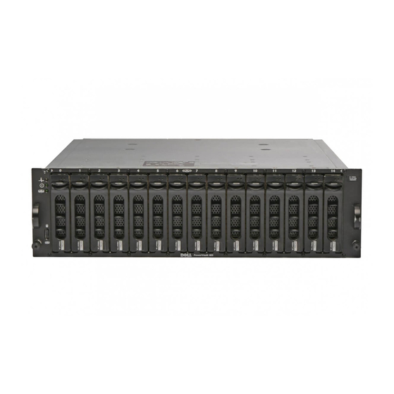
About Your System The Dell™ PowerVault™ MD3000i is a 3U rack-mounted external Redundant Array of Independent Disks (RAID) storage array capable of accommodating up to 15 3.0-Gbps, Serial-Attached SCSI (SAS) disks. The RAID enclosure can be daisy-chained with up to two additional MD1000 expansion enclosures, providing access to a maximum of 45 disks in the entire storage array. - Page 10 – RAID controller modules – NVSRAM – Physical disk NOTE: Dell recommends stopping all I/O to the array when downloading physical disk firmware. – Expansion enclosure management modules (EMMs) • Task-based configuration software (MD Storage Manager) • Optional snapshot virtual disk (premium feature), up to four snapshots per virtual disk and 128 snapshots per array •...
-
Page 11: Modular Disk Storage Manager
Getting Started With Your System provides an overview of enclosure features, setting up your enclosure, and technical specifications. • Setting Up Your PowerVault MD3000i provides an overview of setting up and cabling your storage array. • The PowerVault MD3000i Installation Guide provides installation and configuration instructions for both software and hardware. -
Page 12: Connection Components
Updates are sometimes included to describe changes to the enclosure, software, and/or documentation. NOTE: Always check for updates on support.dell.com and read the updates first because they often supersede information in other documents. • Release notes or readme files are included to provide last-minute updates to the enclosure or documentation or advanced technical reference material intended for experienced users or technicians. -
Page 13: Hardware Features
Each MD3000i RAID controller module also contains a SAS Out port connector. This port allows you the option to connect the RAID enclosure to an expansion enclosure. Refer to the PowerVault MD3000i Installation Guide for details and illustrated examples of how to configure your storage array. Hardware Features... -
Page 14: Front-Panel Indicators And Features
Table 1-1. Front-Bezel Indicators Item LED Indicator LED Icon Condition Split mode (green) Because this mode is unused in the system, this LED should always be unlit. NOTE: This LED comes on if the enclosure mode switch on the enclosure’s front panel is in the split mode position before the enclosure is turned on. - Page 15 Figure 1-2. Front-Panel Features enclosure status power LED split mode LED (not used) enclosure mode physical disks (15) switch Table 1-2. Front-Panel Components Component Icon Condition Enclosure status LED Steady amber: Power is on and enclosure is in (blue/amber) reset state. Steady blue: Power is on and enclosure status is OK.
- Page 16 Table 1-2. Front-Panel Components (continued) Component Icon Condition Power LED (green) When lit, at least one power supply is supplying power to the enclosure. Split mode LED (green) Because this mode is unused in the system, this LED should always be unlit. NOTE: This LED comes on if the enclosure mode switch on the enclosure’s front panel is in the...
- Page 17 Figure 1-3. Physical Disk Carrier LED Indicators activity LED status LED Table 1-3. Physical Disk Carrier Status LEDs Status LED Description Physical disk not yet discovered by host server or an unsupported disk is present Steady green Physical disk is online Green flashing (250 milliseconds Physical disk is being identified [ms])
-
Page 18: Back-Panel Indicators And Features
Back-Panel Indicators and Features Figure 1-4 shows the back-panel features of the enclosure. A fully populated enclosure with dual RAID controllers and two power supply/cooling fan modules is shown. However, a single RAID controller module is supported, and the enclosure can run temporarily on one power supply/cooling fan module. - Page 19 In addition, this configuration provides full redundancy through the use of either redundant disk array controller (RDAC) drivers or multipathing I/O (MPIO) drivers. For detailed information on cabling, see the PowerVault MD3000i Installation Guide. RAID Controller Module Connectors and Features Figure 1-5 shows a single RAID controller module as it appears from the rear of the enclosure.
- Page 20 • Eleven LEDs (two iSCSI In link speed/activity, two iSCSI In link duplex mode, two Ethernet link/speed, battery fault, SAS link fault/connectivity, cache active, controller fault, and controller power) • One SAS Out port connector • Debug port For a description of each component on the front panel of the RAID controller module, see Table 1-4.
- Page 21 Table 1-4. RAID Controller Module Component Functions (continued) Item Component Icon Function iSCSI In Port 1 Link Green: Link is operating at 1000 Mbps. Speed/Activity Amber: Link is operating at 100 Mbps. Status LED Off: iSCSI connection is not active. Battery Fault LED Amber: Battery backup unit or battery has (amber)
- Page 22 LED (green) 100 Mbps. Off: Ethernet connection is operating at 10 Mbps or is not active. Debug Port Dell support only. SAS Link Fault Amber: Between 1–3 links are connected. Green: All four links are connected. Off: All links are down.
- Page 23 Battery Backup Unit Each RAID controller contains a three-cell lithium-ion battery backup unit (BBU) that powers the controller’s cache memory and preserves the cache contents in the event of a power outage of up to 72 hours. The RAID controller firmware performs a test of the BBU at startup and will illuminate the battery fault LED if the battery is not operating within specified ranges, or if the battery is missing.
-
Page 24: Cache Functions And Features
Cache Functions and Features Cache Mirroring The cache mirroring function copies accepted host-write data from the primary controller to the partner controller. This action ensures that host- write data is safely mirrored to the partner controller before successful completion status is returned to the host. If a controller fails, the surviving controller safely retains all mirrored data. - Page 25 CAUTION: A power supply/cooling fan module can be removed from a powered- on enclosure for a maximum period of no more than 5 minutes. Beyond that time, the enclosure may automatically shut down to prevent damage to the enclosure and/or enclosure components. A power supply/cooling fan module can be replaced without powering down the enclosure.
- Page 26 Table 1-5. Power Supply/Cooling Fan Module LED Indicators Type Color Icon Function DC power Green On: DC output voltages are within specifications. Off: No power or voltages not within specifications. Power Amber On: DC output voltages are not within supply/cooling specifications or one (or both) fans are in fault.
-
Page 27: Using Your Raid Enclosure
Using Your RAID Enclosure This section covers the following information: • Basic concepts of a RAID solution including physical disks, virtual disks, and disk groups • RAID levels supported by MD Storage Manager • Hot spare operations and rebuilds • Media errors and unreadable sectors •... -
Page 28: Physical Disks
Number (LUN) that is recognized by the host operating system. Physical Disks Only Dell-supported 3.0-Gbps SAS physical disks are supported in the storage array. If the RAID controller module detects unsupported physical disks, it marks the disk as unsupported and the physical disk becomes unavailable for all operations. -
Page 29: Self-Monitoring Analysis And Reporting Technology (Smart)
Table 2-1. RAID Controller Physical Disk States (continued) Status Mode Description Physical Disk Status LED Indication Failed Assigned, The physical disk in the indicated Amber flashing Unassigned, Hot slot has been failed because of an (125 ms) Spare In Use, or unrecoverable error, an incorrect Hot Spare Standby drive type or drive size, or by its... -
Page 30: Virtual Disks And Disk Groups
Virtual Disks and Disk Groups When configuring a storage array, you would normally proceed in this order: • Organize the physical disks into disk groups. • Create virtual disks within these disk groups. • Determine which host servers you want to grant access to which virtual disks, then create mappings to associate the virtual disks with the host servers. -
Page 31: Supported Raid Levels
Supported RAID Levels RAID levels determine the way in which data is written to physical disks. Different RAID levels provide different levels of accessibility, redundancy, and capacity. Using multiple physical disks has several advantages over using a single physical disk, including: •... -
Page 32: Raid 5
RAID 5 RAID 5 uses parity and striping data across all physical disks (distributed parity) to provide high data throughput and data redundancy, especially for small random access. RAID 5 is the most versatile RAID level and is suited for multi-user environments where typical I/O size is small and there is a high proportion of read activity. -
Page 33: Segment Size
Segment Size Disk striping enables data to be written across multiple physical disks. Disk striping enhances performance because striped disks are accessed simultaneously. The segment size or stripe element size specifies the size of data in a stripe written to a single disk. The MD3000i supports stripe element sizes of 8, 16, 32, 64, 128, 256, and 512 KB. -
Page 34: Rebuild
called copy back. By default, the RAID controller module automatically configures the number and type of hot spares based on the number and capacity of physical disks in your system. A hot spare may have the following states: • A standby hot spare is a physical disk that has been assigned as a hot spare and is available to take over for any failed physical disk. -
Page 35: Raid Operations And Features
Other conditions under which sectors are added to the unreadable sector log include: • A media error is encountered when trying to access a physical disk that is a member of a nonredundant disk group (RAID 0 or degraded RAID 1, RAID 5 or RAID 10). - Page 36 NOTE: Dell recommends that you run data consistency checks on a redundant array at least once a month. This allows detection and automatic replacement of unreadable sectors. Finding an unreadable sector during a rebuild of a failed physical disk is a serious problem, because the system does not have the redundancy to recover the data.
-
Page 37: Disk Group Operations
The RAID controller module tracks the cycle for each disk group independent of other disk groups on the controller and creates a checkpoint. If the media verification operation on a disk group is preempted or blocked by another operation on the disk group, the firmware resumes after the current cycle. If the media verification process on a disk group is stopped due to a RAID controller module restart, the firmware resumes the process from the last checkpoint. - Page 38 Dynamic segment size migration enables the segment size of a given virtual disk to be changed. A default segment size was set when the virtual disk was created, based on such factors as the RAID level and expected usage. You can change the default value if actual usage does not match your needs.
-
Page 39: Raid Background Operations Priority
Disk Group Defragmentation Defragmenting consolidates the free capacity in the disk group into one contiguous area. Defragmentation does not change the way in which the data is stored on the virtual disks. Disk Group Operations Limit The maximum number of active, concurrent disk group processes per controller is one. -
Page 40: Virtual Disk Migration And Disk Roaming
NOTE: Only disk groups and associated virtual disks with all member physical disks present can be migrated from one storage array to another. Dell recommends that you only migrate disk groups that have all their associated member virtual disks in an optimal state. - Page 41 Use either of the following methods to move disk groups and virtual disks: • Hot virtual disk migration — Disk migration with the destination storage array power turned on. • Cold virtual disk migration — Disk migration with the destination storage array power turned off.
-
Page 42: Advanced Features
• Enabling premium features before migration — Before migrating disk groups and virtual disks, enable the required premium features on the destination storage array. If a disk group is migrated from a storage array that has a premium feature enabled and the destination array does not have this feature enabled, an Out of Compliance error message can be generated. - Page 43 Storage partitions give multiple host servers or host groups access to the same host server-to-virtual disk mappings. With these mappings, you can control which host server or host group may have access to a virtual disk in your storage array. The first time you map a virtual disk to a specific host server or host group, a storage partition is created.
-
Page 44: Host Types
You can manually configure a host server-to-virtual disk mapping. When you configure host server-to-virtual disk mapping, consider these guidelines: • You can define one host server-to-virtual disk mapping for each virtual disk in the storage array. • Host server-to-virtual disk mappings are shared between RAID controller modules in the storage array. -
Page 45: Snapshot Repository Virtual Disk
This, in turn, can result in data loss or an inaccessible snapshot. For details on mapping the snapshot virtual disk to the secondary node, refer to the Dell PowerEdge Cluster SE600W Systems Installation and Troubleshooting Guide on support.dell.com. Using Your RAID Enclosure... -
Page 46: Virtual Disk Service
Virtual Disk Service The Microsoft Virtual Disk Service (VDS) is supported on your RAID storage array. Microsoft VDS is a set of application programming interfaces (APIs) that provides a single interface for managing disks and other storage hardware, including creating volumes on those disks. The Microsoft VDS installer service for storage provisioning is available on the MD3000i Resource CD in the \windows\VDS_VSS directory. -
Page 47: Virtual Disk Copy
Storage Management VSS Hardware Provider Tips: • The number of snapshot virtual disks that can be created using a single snapshot set varies with the I/O load on the RAID controller modules. Under little or no I/O load, the number of virtual disks in a snapshot set should be limited to eight. -
Page 48: Using Snapshot And Disk Copy Together
You can find more details on using the virtual disk copy feature in the MD Storage Manager User’s Guide. Virtual Disk Recovery You can use the Edit host server-to-virtual disk mappings feature to recover data from the backup virtual disk. This functionality enables you to unmap the original source virtual disk from its host server, then map the backup virtual disk to the same host server. -
Page 49: Redundancy And Non-Redundancy
NOTE: The best practice for ensuring data access is to avoid a configuration with a single point of failure. A single point of failure is any component or path that is not duplicated (redundant) or whose failure can cause loss of data access. Redundancy and Non-Redundancy Redundancy means that a storage array has duplicate components, or alternate ways to provide essential services. -
Page 50: When A Raid Controller Module Is Replaced Or Removed
Preferred and Alternate Controllers and Paths A preferred controller is a RAID controller module designated as the owner of a virtual disk or disk group. The preferred controller is automatically selected by MD Storage Manager when a virtual disk is created. You can change the preferred RAID controller module owner of a virtual disk after it is created. -
Page 51: Raid Controller Failover Modes
• Failover occurred due to either RAID controller module lockdown, replacement, or path failover. NOTE: Clustering requires simultaneous access from cluster nodes to shared storage. If you have clustering software installed on the host server, automatic failback should be disabled to prevent "ping-pong" with single-path failure. For more information on clustering, a link to clustering documentation is included on the MD3000i Resource CD under Product Documentation. -
Page 52: Thermal Shutdown
Thermal Shutdown Enclosure management provides a feature which automatically shuts down the enclosure when the temperature within the RAID enclosure reaches dangerous extremes. Thermal shutdown protects the data on the physical disks from corruption in the event of a cooling system failure. The temperature at which shutdown occurs is determined by the enclosure temperature probe's Nominal Failure Threshold and the Maximum Failure Threshold. -
Page 53: Physical Disk Firmware
NVSRAM packages separately or together using MD Storage Manager. Physical Disk Firmware NOTE: Dell recommends stopping all I/O to the array when downloading physical disk firmware. You can also download physical disk packages containing the latest firmware files. Ensure that the firmware files you select are compatible with the physical disks. -
Page 54: Best Practices And Recommendations
Ethernet data or across the Internet, set up Challenge Handshake Authentication Protocol (CHAP) security to authenticate all access to the iSCSI ports on both the host server and the storage array. Refer to the PowerVault MD3000i Installation Guide for information on configuring CHAP. •... -
Page 55: Installing Enclosure Components
Installing Enclosure Components This section explains how to install the following components: • Front bezel (optional) • Physical disks and disk carriers • RAID controller modules • Battery backup unit • Power supplies • Control panel • Enclosure midplane Recommended Tools The procedures in this section require the use of one or more of the following tools: •... -
Page 56: Removing And Installing Physical Disks
Figure 3-1. Installing and Removing the Front Bezel bezel lock release tab/interlocking notch U-shaped handle 4 To replace the bezel, insert the interlocking notch into the U-shaped handle on the side of the front enclosure panel. 5 Snap the left side of the bezel into place in the U-shaped handle on the left side of the enclosure. -
Page 57: Removing Physical Disks From The Enclosure
NOTICE: To avoid data loss when removing a physical disk, Dell recommends that you verify with MD Storage Manager that the appropriate disk is being removed. Removing an Assigned physical disk could result in data loss. -
Page 58: Installing Sas Physical Disks In The Enclosure
3 Open the physical disk carrier handle by rotating it downward. 4 Gently but firmly pull the physical disk carrier from its slot while supporting the weight of the disk from the bottom. Installing SAS Physical Disks in the Enclosure NOTICE: To ensure proper airflow for enclosure cooling, each slot should contain either an active physical disk or a disk blank. - Page 59 Figure 3-3. Installing a SAS Physical Disk in the Carrier screws (4) physical disk carrier physical disk 2 With the physical disk carrier handle open, carefully align the channel on the disk carrier guide rail with the appropriate disk slot keying feature on the chassis face plate, and insert the disk (see Figure 3-2).
-
Page 60: Removing And Installing A Raid Controller Module
4 Rotate the carrier handle to the closed position while continuing to push the carrier into the slot. The status LED indicator (see Table 1-3 for description) will display a steady green if the physical disk is inserted properly. If the indicator is not illuminated, see "Troubleshooting SAS Physical Disks"... -
Page 61: Installing A Raid Controller Module
Figure 3-4. Removing and Installing a RAID Controller Module release tab release lever Installing a RAID Controller Module 1 Carefully insert the RAID controller module into the empty module slot. 2 Push the module to the back of the slot until it is firmly seated in the backplane connector (see Figure 3-4). -
Page 62: Removing And Installing A Raid Controller Module Backup Battery Unit
Removing and Installing a RAID Controller Module Backup Battery Unit Each RAID controller module has a battery unit that provides backup power for the data cache memory. The battery unit is mounted inside the RAID controller module and connects to the controller circuit board. This section describes how to remove and replace the battery unit. - Page 63 Figure 3-5. Removing and Installing a RAID Controller Module Backup Battery Unit thumbscrew battery cover battery unit 4 Unscrew the thumbscrew holding the battery unit to the controller module. 5 Disconnect the battery unit from the connector by sliding it towards the back of the controller, then remove it from the controller module.
-
Page 64: Removing And Installing The Power Supply/Cooling Fan Module
Removing and Installing the Power Supply/Cooling Fan Module Your enclosure supports two separate modules containing an integrated power supply and two cooling fans per module. While the enclosure can operate temporarily with only one functional power supply, both cooling modules (with two fans each) must be present for proper cooling. -
Page 65: Installing A Power Supply/Cooling Fan Module
Figure 3-6. Replacing the Power Supply power supply captive screws (2) handle on/off switch CAUTION: The power supply/cooling fan modules are heavy. Use both hands when removing. 3 Grasp the handle on the power supply and carefully pull the module out of the bay (see Figure 3-6). -
Page 66: Removing And Installing The Control Panel
2 Gently push the module all the way to the back of the bay until it is firmly seated in the backplane connector. The power supply is seated when its front plate is even with the front plate of the adjacent power supply. NOTE: If the enclosure is powered on, the power-supply fault indicator (see Figure 1-7) remains illuminated until you connect the AC power cable to the... -
Page 67: Installing The Control Panel
Figure 3-7. Removing and Replacing the Control Panel faceplate screws (16) control panel thumbscrews 6 Using a Torx T10 driver, remove all 16 screws from the front faceplate of the enclosure as shown in Figure 3-7. 7 Remove the front faceplate from the enclosure and place it on a flat, secure surface. -
Page 68: Removing And Installing The Midplane
2 Slide the control panel fully into the slot, making sure that its connector engages into the matching backplane connector (see Figure 3-7). Also, make sure the guide tab on the control panel is fully inserted into the mounting slot on the backplane. 3 Replace the front faceplate and re-attach the 16 screws that hold it in place. - Page 69 Figure 3-8. Removing and Replacing the Controller/Power Supply Cage Phillips screws (4) controller/power supply cage 5 Slide the controller/power supply cage out of the enclosure and place it aside. 6 Reaching into the enclosure chassis from the back, carefully disconnect the midplane from the control panel and lift it out of the enclosure (see Figure 3-9).
- Page 70 Figure 3-9. Removing and Installing the Midplane midplane Installing Enclosure Components...
-
Page 71: Troubleshooting Your Enclosure
Troubleshooting Your Enclosure Safety First—For You and Your Enclosure To perform certain procedures in this document, you must work inside the enclosure. While working inside the enclosure, do not attempt to perform service except as explained in this guide and elsewhere in your documentation. -
Page 72: Troubleshooting External Connections
Troubleshooting External Connections Loose or improperly connected cables and bent pins are the most likely source of problems. Ensure that all external cables are securely attached to the external connectors on your system and that none of the connectors are damaged. See "Back-Panel Indicators and Features"... -
Page 73: Troubleshooting A Damaged Enclosure
Troubleshooting a Damaged Enclosure Problem • Enclosure was dropped or damaged. Action CAUTION: Only trained service technicians are authorized to remove the enclosure cover and access any of the components inside the enclosure. Before performing any procedure, see your Product Information Guide for complete information about safety precautions, working inside the enclosure and protecting against electrostatic discharge. - Page 74 Action CAUTION: Only trained service technicians are authorized to remove the enclosure cover and access any of the components inside the enclosure. Before performing any procedure, see your Product Information Guide for complete information about safety precautions, working inside the enclosure and protecting against electrostatic discharge.
-
Page 75: Troubleshooting Enclosure Cooling Problems
5 Install a new power supply. See "Removing and Installing the Power Supply/Cooling Fan Module" on page 64. If the problem persists, see "Getting Help" on page 81. Troubleshooting Enclosure Cooling Problems Problem • MD Storage Manager issues a fan-related error message. •... -
Page 76: Troubleshooting Sas Physical Disks
CAUTION: The cooling fans are hot-pluggable. To maintain proper cooling while the system is on, replace only one fan at a time. 1 Locate the malfunctioning fan. 2 Ensure that the faulty power supply/cooling fan module is properly connected to the enclosure midplane. 3 If the problem is not resolved, install a new power supply/cooling fan module. -
Page 77: Troubleshooting Enclosure Connections
Enclosure is not seen by attached host server. Action • Inspect RAID controller module cables for connectivity problems, such as damaged or disconnected cables and poor connections. For detailed cabling instructions, see the PowerVault MD3000i Installation Guide. Troubleshooting Your Enclosure... -
Page 78: Hard Controller Failures And Lockdown Conditions
Typical hard controller failures are detailed in the following sections. Invalid Enclosure The RAID controller module is supported only in a Dell-supported enclosure. Upon installation in the enclosure, the controller performs a set of validation checks. The enclosure status LED is lit with a steady amber color while the RAID controller module completes these initial tests and the controllers are booted successfully. -
Page 79: Pci Errors
PCI Errors The storage enclosure firmware can detect and only recover from PCI errors when the RAID controller modules are configured for redundancy. If a virtual disk uses cache mirroring, it fails over to its peer RAID controller module, which initiates a flush of the dirty cache. Critical Conditions The storage array will generate a critical event if the RAID controller module detects a critical condition that could cause immediate failure of the... - Page 80 Troubleshooting Your Enclosure...
-
Page 81: Getting Help
(support.dell.com) for help with installation and troubleshooting procedures. For more information, see "Online Services" on page 82. 4 If the preceding steps have not resolved the problem, call Dell for technical assistance. NOTE: Call the support service from a phone near or at the system so that the support staff can assist you with any necessary procedures. -
Page 82: Technical Support And Customer Service
Dell's support service is available to answer your questions about Dell™ hardware. Our support staff use computer-based diagnostics to provide fast, accurate answers. To contact Dell's support service, see "Before You Call" on page 84, and then see the contact information for your region or go to support.dell.com. Online Services You can learn about Dell products and services on the following websites: www.dell.com/... -
Page 83: Automated Order-Status Service
Log in as user: anonymous, and use your e-mail address as your password. Automated Order-Status Service To check on the status of any Dell™ products that you have ordered, you can go to support.dell.com, or you can call the automated order-status service. A recording prompts you for the information needed to locate and report on your order. -
Page 84: Before You Call
Before You Call NOTE: Have your Express Service Code ready when you call. The code helps Dell's automated-support telephone system direct your call more efficiently. If possible, turn on your system before you call Dell for technical assistance and call from a telephone at or near the system. - Page 85 Dell provides several online and telephone-based support and service options. Availability varies by country and product, and some services may not be available in your area. To contact Dell for sales, technical support, or customer service issues: 1 Visit support.dell.com.
- Page 86 Getting Help...
-
Page 87: Glossary
Glossary This section defines or identifies technical terms, abbreviations, and acronyms used in your system documents. A — Ampere(s). AC — Alternating current. ACPI — Advanced Configuration and Power Interface. A standard interface for enabling the operating system to direct configuration and power management. ambient temperature —... - Page 88 BIOS — Basic input/output system. Your system’s BIOS contains programs stored on a flash memory chip. The BIOS controls the following: • Communications between the processor and peripheral devices • Miscellaneous functions, such as system messages bit — The smallest unit of information interpreted by your system. blade —...
- Page 89 component — As they relate to DMI, components include operating systems, computer systems, expansion cards, and peripherals that are compatible with DMI. Each component is made up of groups and attributes that are defined as relevant to that component. COMn — The device names for the serial ports on your system. control panel —...
- Page 90 DNS — Domain Name System. A method of translating Internet domain names, such as www.dell.com, into IP addresses, such as 143.166.83.200. DRAM — Dynamic random-access memory. A system’s RAM is usually made up entirely of DRAM chips.
- Page 91 expansion card — An add-in card, such as a NIC or SCSI adapter, that plugs into an expansion-card connector on the system board. An expansion card adds some specialized function to the system by providing an interface between the expansion bus and a peripheral.
- Page 92 group — As it relates to DMI, a group is a data structure that defines common information, or attributes, about a manageable component. guarding — A type of data redundancy in which a set of physical disks stores data and an additional disks stores parity data.
- Page 93 IP — Internet Protocol. IPX — Internet package exchange. IRQ — Interrupt request. A signal that data is about to be sent to or received by a peripheral device travels by an IRQ line to the processor. Each peripheral connection must be assigned an IRQ number.
- Page 94 LAN — Local area network. A LAN is usually confined to the same building or a few nearby buildings, with all equipment linked by wiring dedicated specifically to the LAN. lb — Pound(s). LCD — Liquid crystal display. LED — Light-emitting diode. An electronic device that lights up when a current is passed through it.
- Page 95 memory address — A specific location, usually expressed as a hexadecimal number, in the system’s RAM. memory module — A small circuit board containing DRAM chips that connects to the system board. memory — An area in your system that stores basic system data. A system can contain several different forms of memory, such as integrated memory (ROM and RAM) and add-in memory modules (DIMMs).
- Page 96 parity — Redundant information that is associated with a block of data. partition — You can divide a physical disk into multiple physical sections called partitions with the fdisk command. Each partition can contain multiple logical disks. You must format each logical disk with the format command. PCI —...
- Page 97 PS/2 — Personal System/2. PXE — Preboot eXecution Environment. A way of booting a system via a LAN (without a physical disk or bootable diskette). RAC — Remote access controller. RAID — Redundant array of independent disks. A method of providing data redundancy.
- Page 98 — An I/O port used most often to connect a modem to your system. You can usually identify a serial port on your system by its 9-pin connector. service tag — A bar code label on the system used to identify it when you call Dell for technical support.
- Page 99 SVGA — Super video graphics array. VGA and SVGA are video standards for video adapters with greater resolution and color display capabilities than previous standards. system board — As the main circuit board, the system board usually contains most of your system’s integral components, such as the processor, RAM, controllers for peripherals, and various ROM chips.
- Page 100 USB — Universal Serial Bus. A USB connector provides a single connection point for multiple USB-compliant devices, such as mice and keyboards. USB devices can be connected and disconnected while the system is running. utility — A program used to manage system resources—memory, disk drives, or printers, for example.
- Page 101 win.ini file — A start-up file for the Windows operating system. When you start Windows, it consults the win.ini file to determine a variety of options for the Windows operating environment. The win.ini file also usually includes sections that contain optional settings for Windows application programs that are installed on the physical disk.
- Page 102 Glossary...
- Page 103 Index enclosure management module, 18 consistency check, 36 external connections contacting Dell, 84 troubleshooting, 72 control panel installing/removing, 66 cooling fan features, 24 firmware, 52 troubleshooting, 75 front bezel indicators, 14 removing and replacing, 55 front-panel indicators damaged systems LED indicators, 15...
- Page 104 37 storage management software See MD Storage Manager phone numbers, 84 storage management station, 11 physical disk support about, 27 contacting Dell, 84 consistency check, 36 installing, 58 system cooling mode, status, 28 troubleshooting, 75 removing, 57 troubleshooting, 76...
- Page 105 virtual disk about, 27 initializing, 35 migration, 40 recovery, 48 warranty, 11 Index...
- Page 106 Index...