
Related Manuals for KTI Networks KGS-1260/G


Summary of Contents for KTI Networks KGS-1260/G
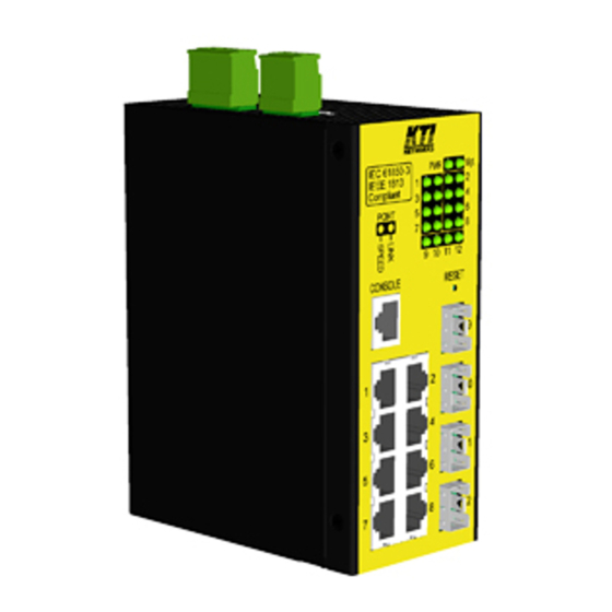
- Page 1 KGS-1260/G (Basic) KGS-1260/I (IEC 61850-3 enhanced) Industrial Managed 12-port Gigabit Ethernet Switches Installation Guide DOC.180817D...
- Page 2 (C) 2018 KTI Networks Inc. All rights reserved. No part of this documentation may be reproduced in any form or by any means or used to make any directive work (such as translation or transformation) without permission from KTI Networks Inc.
- Page 3 The information contained in this document is subject to change without prior notice. Copyright (C) All Rights Reserved. TRADEMARKS Ethernet is a registered trademark of Xerox Corp. FCC NOTICE This device complies with Part 15 of the FCC Rules. Operation is subject to the following two conditions: (1) This device may not cause harmful interference, and (2) This device must accept any interference received, including the interference that may cause undesired operation.
-
Page 4: Table Of Contents
Table of Contents 1. Introduction ........................... 6 1.1 Model Definitions ....................6 1.2 Features ......................7 1.3 LED Indicators ..................... 8 1.4 Specifications ...................... 8 1.5 IEC 61850-3 & IEEE 1613 ................. 11 2. Installation ........................... 13 2.1 Unpacking ......................13 2.2 Safety Cautions .................... - Page 5 5.1 Auto Multi-Ring Technology ................33 5.2 Redundant Ring Applications with industrial standard RSTP protocol ....34...
-
Page 6: Introduction
Eight 10/100/1000Mbps Gigabit copper ports Four dual-speed SFP slots for 100Base-FX 1000Base-X One RS-232 console port 1.1 Model Definitions IEC 61850-3 & IEEE 1613 Model Description Enhanced KGS-1260/G Industrial Managed 12-port Gigabit Ethernet Switch KGS-1260/I IEC 61850-3 Managed 12-port Gigabit Ethernet Switch... -
Page 7: Features
1.2 Features Eight 10/100/1000Mbps RJ-45 and four dual-speed SFP slots All copper ports support auto-negotiation and auto-MDI/MDI-X detection. Four SFP slots support dual speed for 100BASE-FX and 1000BASE-X SFP transceivers. Full wire speed forwarding Supports 802.3x flow control for full-duplex and backpressure for half-duplex ... -
Page 8: Led Indicators
1.3 LED Indicators Function Power status Mgt. Management status Port 1~ 8 SPEED LEDs Speed status Port 1~ 8 LINK LEDs Link & activity status SFP 9~12 LEDs Speed & link & activity status of SFP port 1.4 Specifications 10/100/1000 Copper Ports (Port 1 ~ Port 8) Compliance IEEE 802.3 10Base-T, IEEE 802.3u 100Base-TX, IEEE 802.3u 1000Base-T Connectors... - Page 9 4, 5 Switch Functions MAC Addresses Table 8K entries Forwarding & filtering Non-blocking, full wire speed Switching technology Store and forward Maximum packet length 9.6K bytes IP Multicast groups 8192 supported Flow control IEEE 802.3x pause frame base for full duplex operation Back pressure for half duplex operation DC IN Terminal Block Pin assignments...
- Page 10 ~ +70 ℃ ℃ Storage Temperature ~ +85 Relative Humidity 5% ~ 95% non-condensing MTBF KGS-1260/G 212K hours KGS-1260/I 212K hours Tests and Approvals FCC Part 15 rule Class A CE EMC Class A VCCI Class A EN 55032 Emission IEC 55024 Immunity IEC 61850-3 EMC &...
-
Page 11: Iec 61850-3 & Ieee 1613
1.5 IEC 61850-3 & IEEE 1613 KGS-1260/I model has been enhanced and verified with compliance for IEC 61850-3 EMC, environmental and mechanical requirements and IEEE 1613 requirements for power substations. IEC 61850-3 IEC 61850-3 defines the general requirements, mainly regarding construction, design and environmental conditions for utility communication and automation IEDs (intelligent electronic devices) and systems in power plant and substation environments. - Page 12 +40℃, 95%RH, 48hrs C 6.9.3 Damp heat – steady state C 6.9.3 Humidity +25℃95%RH 12hrs/ C 95%RH 12hrs, 2 cycles +85℃, 30%RH, 96hrs C 6.9.3 Dry heat - storage -40℃, 96hrs C 6.9.3 Cold – storage IEC 61850-3 Mechanical Test Specifications IEC 61850-3 Test Specification...
-
Page 13: Installation
2. Installation 2.1 Unpacking The product package contains: The device unit for Din-rail mounting QR code label linking to product documentation cloud 2.2 Safety Cautions To reduce the risk of bodily injury, electrical shock, fire and damage to the product, observe the following precautions. -
Page 14: Din-Rail Mounting
2.3 DIN-Rail Mounting In the product package, a DIN-rail bracket is provided for mounting the switch in an industrial DIN-rail 1 7 1 B enclosure. T he steps to mount the switch onto a DIN rail are: 1 7 2 B Install the mounting bracket onto the switch unit as shown below: 1 2 8 7 B A ttach bracket to the lower edge of the DIN rail and push the unit upward a little bit until the bracket can... - Page 15 KGS-1260/G and KGS-1260/I have the same dimension as follows: -15-...
-
Page 16: Panel Mounting
2.4 Panel Mounting T he switch is provided with an optional panel mounting bracket. The bracket supports mounting the switch on 1 7 3 B a plane surface securely. The mounting steps are: Install the mounting bracket on the switch unit. 1 2 9 0 B S crew the bracket on the switch unit. - Page 17 KGS-1260/G and KGS-1260/I have the same dimension as follows: -17-...
-
Page 18: Applying Power
2.5 Applying Power DC Power Terminal Block For supporting power redundancy, the device is featured with two DC power input interfaces, DC input A and input B that enable to receive power from two different power sources. 2.5.1 DC power Terminal Block Connector: European 4P terminal block &... -
Page 19: Alarm Relay Output
2.6 Alarm Relay Output Alarm relay output is provided for reporting failure events to a remote alarm relay monitoring system. The replay output is provided with three contacts on a terminal block connector. Alarm Relay (AR) output pins and logic: Alarm relay output, NO (Normal Open) contacts Normal: Open, Alarm: Shorted Alarm relay output, NC (Normal Close) contacts... -
Page 20: Reset Button
2.7 Reset Button The reset button is used to perform a reset to the device. It is not used in normal cases and can be used for diagnostic purpose. If any network hanging problem is suspected, it is useful to push the button to reset the device without turning off the power. -
Page 21: Making Lan Connections
3. Making LAN Connections 3.1 10/100/1000 TP Copper Port The 10/100/1000 TP copper port supports the following connection types and distances: Network Cables 10BASE-T: 2-pair UTP Cat. 3, 4, 5 , EIA/TIA-568B 100-ohm 100BASE-TX: 2-pair UTP Cat. 5, EIA/TIA-568B 100-ohm 1000BASE-T: 4-pair UTP Cat. -
Page 22: Making Fiber Connection
devices. The port performs a negotiation process for the speed and duplex configuration with the connected device automatically when each time a link is being established. If the connected device is also auto-negotiation capable, both link partners will come out the best configuration after negotiation process. If the connected device is incapable in auto-negotiation, the port will sense the speed and use half duplex for the connection. -
Page 23: Making Console Connection
transceivers. Connecting Fiber Cables LC connectors are commonly equipped on most SFP transceiver modules. Identify TX and RX connector before making cable connection. The following figure illustrates a connection example between two fiber ports: Make sure the Rx-to-Tx connection rule is followed on the both ends of the fiber cable. Network Cables Multimode (MMF) - 50/125, 62.5/125 Single mode (SMF) - 9/125... - Page 24 The connector designed for the console port is RJ-45. Pin Assignments RS-232 signals IN/OUT 1, 2, 7, 8 4, 5 Baud Rate information Baud rate - 115200 Data bits - 8 Parity - None Stop bit - 1 Flow control – None -24-...
-
Page 25: Led Indication
3.4 LED Indication Function Color State Interpretation Power Green The power is supplied to the switch. status The power is not supplied to the switch. Management status Green BLINK The switch is in initialization and diagnostics. Yellow BLINK Initialization completed with diagnostic error or system Green Initialization completed with no error... -
Page 26: Manage The Switch
4. Manage the Switch The switches provide the following methods to configure and monitor the switch as follows: Making out of band telnet CLI management via the console port Making in-band management via telnet CLI over TCP/IP network ... -
Page 27: Configuring Ip Address Via Web Interface
Parameters: <ipv6_addr> : IPv6 address is in 128-bit records represented as eight fields of up to four hexadecimal digits with a colon separates each field (:). <ipv6_prefix> : IPv6 subnet mask <ipv6_router> : IPv6 router [Password] setting command is also in Security/Switch/Users command group. Security Switch Users Configuration Security Switch Users Add <user_name>... - Page 28 No password is required. Click to login into the switch. Web Page after a Successful Login Select [Configuration] -> [System] -> [IP] to configure IP address -28-...
-
Page 29: Reference Manuals For Web, Console, Telnet Management
Configuration Description DHCP Client Enable the DHCP client by checking this box. IP Address Provide the IP address of this switch unit. IP Mask Provide the IP mask of this switch unit. IP Router Provide the IP address of the default router for this switch unit. Provide the managed VLAN ID. -
Page 30: Configuration For Snmp Management
4.5 Configuration for SNMP Management The switch supports SNMP v1, SNMP v2c, and SNMP v3 management. Make sure the related settings are well-configured for the switch before you start the SNMP management from an SNMP manager. Using Telnet Interface The following are available commands in telnet SNMP command group to configure SNMP-related settings: >SNMP Configuration >SNMP Mode [enable|disable] >SNMP Version [1|2c|3]... -
Page 31: Snmp Mibs
>SNMP View Delete <index> >SNMP View Lookup [<index>] >SNMP Access Add <group_name> <security_model> <security_level> [<read_view_name>] [<write_view_name>] >SNMP Access Delete <index> >SNMP Access Lookup [<index>] Using Web Interface Select [Configuration] -> [Security] -> [SNMP]: The commands supports configuration for: Basic system configuration for SNMP v1 and SNMP v2c Basic system configuration for SNMP v1 trap, SNMP v2c trap and SNMP v3 trap Communities that permit to access to SNMPv3 agent USM (User-based Security Model) user table for SNMPv3... -
Page 32: Snmp Traps
- RFC 4188 - Bridge MIB - RFC 4668 - RADIUS Authentication Client MIB - RFC 5519 - Multicast Group Membership Discovery (MGMD) MIB - IEEE 802.1 MSTP MIB - IEEE 802.1AB LLDP MIB - IEEE 802.1X Port Access Entity (PAE) MIB - TIA 1057 LLDP Media Endpoint Discovery (MED) MIB - IEEE 802.1-Q-BRIDGE MIB - Private SFPDDM MIB (Read DDM status of the SFP ports) -
Page 33: Redundant Ring Applications
5. Redundant Ring Applications 5.1 Auto Multi-Ring Technology Auto Multi-Ring Technology was developed especially for switches connected in ring topology which needs redundant support when any failure occurs in ring. For large network, more than one ring connections are very common. - Page 34 The following figure shows one switch is configured to support three redundant rings and one RSTP ring at the same time. 5.2 Redundant Ring Applications with industrial standard RSTP protocol It also can be done to support a ring connection using industrial standard RSTP function and establish a backup path.