
Related Manuals for KTI Networks KGS-0600


Summary of Contents for KTI Networks KGS-0600
- Page 1 KGS-0600 Web Smart 6-Port Gigabit Ethernet Switch with 1 mini-GBIC Port User s Manual DOC.120206...
- Page 2 (C) 2012 KTI Networks Inc. All rights reserved. No part of this documentation may be reproduced in any form or by any means or used to make any directive work (such as translation or transformation) without permission from KTI Networks Inc.
- Page 3 The information contained in this document is subject to change without prior notice. Copyright (C) All Rights Reserved. TRADEMARKS Ethernet is a registered trademark of Xerox Corp. FCC NOTICE This device complies with Class A Part 15 the FCC Rules. Operation is subject to the following two conditions: (1) This device may not cause harmful interference, and (2) this device must accept any interference received including the interference that may cause.
-
Page 4: Table Of Contents
Table of Contents 1. Introduction ......................5 2. Highlight Features ....................5 3. Product Panels......................6 4. LED Indicators ......................6 5. Specifications ......................6 6. Installation ....................... 8 7. Mounting the Switch on a Wall................9 8. Applying Power ....................... 9 9. -
Page 5: Introduction
1. Introduction The KGS-0600 is a Gigabit Ethernet switch which is featured with the following switched ports: Five 10/100/1000Mbps Gigabit copper ports One 1000Base-X SFP port It provides five 10/100/1000Mbps copper ports for connections to Ethernet, Fast Ethernet, and Gigabit Ethernet devices. -
Page 6: Product Panels
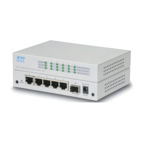
3. Product Panels The following figure illustrates the front panel and rear panel of the switch: 4. LED Indicators Function POWER Power status 1000M/LINK/ACT Network port 1000M link status (Port 1 - Port 5) 100M/LINK/ACT Network port 100M link status (Port 1 - Port 5) 10M/LINK/ACT Network port 10M link status (Port 1 - Port 5) P6 LINK... - Page 7 Network cable Cat.5 UTP 1000Mbps Mini-GBIC SFP Compliance IEEE 802.3z 1000Base-SX/LX (mini-GBIC) Connectors SFP for optional SFP type fiber transceivers Configuration Auto/Forced, 1000Mbps, Full duplex Transmission rate 1000Mbps Network cables MMF 50/125 60/125, SMF 9/125 Eye safety IEC 825 compliant Switch Functions MAC Addresses Table 8K entries...
-
Page 8: Installation
6. Installation Unpacking The product package contains: The switch unit One power adapter One product CD-ROM Safety Cautions To reduce the risk of bodily injury, electrical shock, fire and damage to the product, observe the following precautions. Do not service any product except as explained in your system documentation. Opening or removing covers may expose you to electrical shock. -
Page 9: Mounting The Switch On A Wall
7. Mounting the Switch on a Wall The switch can be mounted on a desktop or shelf or a wall. Make sure that there is proper heat dissipation from and adequate ventilation around the device. Do not place heavy objects on the device. 8. -
Page 10: Reset Button
9. Reset Button The reset button is used to perform a reset to the switch. It is not used in normal cases and can be used for diagnostic purpose. If any network hanging problem is suspected, it is useful to push the button to reset the switch without turning off the power. -
Page 11: Making Fiber Connection
11. Making Fiber Connection The SFP slot must be installed with an SFP fiber transceiver for making fiber connection. Your switch may come with some SFP transceivers pre-installed when it is shipped. Installing SFP Fiber Transceiver To install an SFP fiber transceiver into SFP slot, the steps are: 1. - Page 12 Connecting Fiber Cables LC connectors are commonly equipped on most SFP transceiver modules. Identify TX and RX connector before making cable connection. The following figure illustrates a connection example between two fiber ports: Make sure the Rx-to-Tx connection rule is followed on the both ends of the fiber cable. Network Cables Multimode (MMF) - 50/125μm, 62.5/125μm Single mode (SMF) - 9/125...
-
Page 13: Led Indication
12. LED Indication Function State Interpretation POWER Power status The power is supplied to the switch. The power is not supplied to the switch. 1000M/LINK/ACT Port link status A 1000Mbps link is established. (No traffic) BLINK Port link is up and there is traffic. Port link is down.