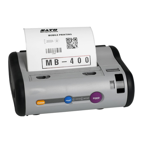
SATO MB400 User Manual
Sato user's guide printer mb400
Hide thumbs
Also See for MB400:
- Quick manual (24 pages) ,
- Parts list (12 pages) ,
- Specifications (2 pages)

Related Manuals for SATO MB400


Summary of Contents for SATO MB400
- Page 1 User’s Guide Barcode Printer MB400 Thank you for your purchase of the SATO MB400 barcode printer. Make sure to read this operation manual and keep it in a handy place. PN9001114 PN9001114...
- Page 2 Introduction Thank you for your purchase of the SATO MB400 barcode printer. This manual helps first time users understand the basics of the printer in a short period of time. To get the most out of the functions of the printer, make sure to read this manual carefully.
- Page 3 With a compact and lightweight body and high performance, this printer prints barcodes clearly on various types of thermal paper. Excellent Printing Performance Not only does this printer print barcodes clearly, but it can also enlarge and print various types of fonts a in a free layout. Durable and Easy to Use This printer is also superb in durability, as it has been designed specifically for printing barcodes.
-
Page 4: Table Of Contents
Loading Labels (Continuous mode)...20 Loading Labels (Dispense mode) ...24 Adjusting the Position of the Label Sensor ...25 5. Turning on the Power...26 6. Starting the Printer ...27 Procedures for On-line Operation...28 On-line Operation ...30 Using the Shoulder Belt ...32 IrDA adjustment Lever ...34 7. -
Page 5: Safety Precautions
Make sure to read these carefully before using your printer. Markings and Symbols The following symbols or markings are used in this user’s guide and on the printer so that you can properly use the printer, and to prevent any damage to property, harm or injury to yourself and others. - Page 6 Abnormal Conditions Do not use the printer if it is emitting smoke or strange odors. Continued use creates the danger of fire and electrical shock. * Immediately turn off the power and contact your nearest dealer or service center for repairs.
- Page 7 Disassembly Never try to take the unit apart or modify it in any way. Doing so creates the danger of fire or electrical shock. * Contact your nearest dealer or Customer Service Center for checkups, tuning and repairs. * For checkups, tuning and repairs, contact your nearest dealer or Customer Service Center.
- Page 8 Safety Precautions Warning AC Adapter / Battery Charger (Optional) Use only the specified voltage. Using a different voltage may create the danger of fire or electrical shock. Never use the battery charger with any other battery pack except for the specified one. Doing so creates the danger of fire and electrical shock.
- Page 9 Location Do not locate the printer in areas subjected to high humidity or dew. Doing so creates the danger of electrical shock. * If dew forms inside the printer, immediately turn off the power and do not use it until it has dried up.
- Page 10 When disposing of old battery packs, make sure to contact your nearest dealer or service center. Not using the printer for a long time Remove the battery pack from the printer and unplug the AC adapter from the wall outlet. Maintenance and Cleaning For safety during maintenance and cleaning, make sure to remove the battery pack and the AC adapter from the printer.
-
Page 11: Precautions In Use
The operation temperature range is within 0°C to 50°C. Do not place it in areas with himidity or temperature out of the operation range. Do not place the printer in locations exposed to direct sunlight or places of high temperatures. -
Page 12: Unpacking
Unpacking After opening the box, make sure that all the printer’s accessories are included. If there are any accessories missing, contact your nearest dealer or service center. 1 Printer 2 Battery pack (standard or optional) 3 Shoulder belt 4 User’s guide... -
Page 13: Part Names
Part Names (1) Dispense/Continuous switch lever Switches the print mode (dispense/ continuous). (2) Dispenser unit Move this when the Dispense mode is selected. (3) Front cover Open/Close lever Opens and closes the front cover. (4) Front cover Open this for setting labels. PN9001114 (5) Easy cutter Cuts printed labels. - Page 14 Use this when fixing the position of the label guide. Page 14 (5) Shoulder belt hook Attaches the shoulder belt when hanging the printer on shoulder. (6) Adjustment screwdriver (supplied accessory) (7) IrDA filter The IrDA receiving element is located inside.
-
Page 15: Name And Function Of Operating Parts
Operation part names POWER key Turns the power on and off. PRINT key Sets the printer to on-line or off-line. FEED key Feeds labels. (9) Interface cover Covers the interface connector. (The cable lock is included.) (10)Interface connector (RS-232C) Connects to a computer. -
Page 16: Before Starting
Before Starting Charging the Battery Pack You can recharge the battery pack by inserting it into the battery charger (optional). (1) Plug one end of the AC adapter into the battery charger and the other end into the wall outlet. (2) Insert the battery pack. - Page 17 Sep. 1st, 2000.) • The battery pack cannot be used when using the AC adapter. If the AC adapter jack is plugged into the printer when using the battery, the power will be reset. (If there is any remaining print data, it will be lost.)
-
Page 18: Installing And Removing The Battery Pack
Before Starting Installing and Removing the Battery Pack (1) Place your finger on the battery cover ribbed area, and open the battery cover in the direction of the arrow. (2) Insert the battery pack. Insert the battery pack with the connector facing towards the end. -
Page 19: Battery Status
• Make sure to turn the power off before removing or replacing the battery pack. • If you do not plan to use the printer for long period of time, make sure to remove the battery pack. If not removed, the battery may get over-discharged and may not be recharged. -
Page 20: Loading Labels (Continuous Mode)
Before Starting ... The method of loading the labels may vary depending Loading Labels on the print mode. [Continuous Mode] Labels non-dispensed labels adhesive backed labels (1) Press the cover Open/Close lever in the direction of the arrow to release the front cover lock. - Page 21 (3) Open the front cover in the direction of the arrow. (4) Insert the label roll on the label guide boss inside the front cover. • Press the tab for adjusting the label guide (right), and adjust the guide to the width of the labels to be used.
-
Page 22: Loading Labels
Before Starting ... The method of loading the labels may vary depending Loading Labels on the print mode. [Continuous Mode] (Continued from page 21) (5) After peeling the lead tape on the roll, take the leading edge of the first label on the roll and pull it out via the platen roller. - Page 23 Core-less rolls After removing both of the label guide bosses on the sides with the driver (attached accessory), set the roll by following the directions 4, 5 and 6 on page 21 to 22. Label guide boss Setting the Label Guide Boss If the width of the label is fixed, the boss can be fixed.
-
Page 24: Loading Labels (Dispense Mode)
Before Starting ... The method of loading the label may vary depending on Loading Labels the print mode. [Dispense Mode] First perform the procedure steps 1 through 6 on pages 22 and 23 (Continuous mode). • Pick the Dispense/Continuous switch lever from both sides, and slide the Dispenser unit to the direction of the arrow. -
Page 25: Adjusting The Position Of The Label Sensor
Adjusting the Position of the Label Sensor (1) Moving the Label Sensor to the Right Turn the Label Sensor Adjustment Dial up. (2) Moving the label Sensor to the Left Turn the Label Sensor Adjustment Dial down. Using the Sensor Align the right edge of the sensor with the right edge of the label. -
Page 26: Turning On The Power
STATUS LED indicator is off before taking out the battery pack. • If the battery pack is removed after the power is turned off, but with the STATUS LED indicator still lit up in green, the printer may not refresh the data in memory... -
Page 27: Starting The Printer
There are two modes for printing: the Continuous mode and the Dispense mode. Test printing and On-line printing can be done on both modes. Continuous Printing Test Printing Dispense Printing Printing in Printer condition Continuous Printing On-line Printing Dispense Printing Printing in Printer... -
Page 28: Procedures For On-Line Operation
Off-line Power Save Mode 1. Sleep Mode The printer will go into the Sleep mode if not performed any operation for 5 seconds. Pressing the PRINT key or the FEED key, or receiving data will resume normal status. Page 28... - Page 29 Test Print Mode (printing) Suspension 2. Auto Power Off Mode The printer will go into the Auto Power Off Mode if not operated for 5 minutes. Be careful as the printing data, if any, will not be saved. PN9001114 Status (LED)
-
Page 30: On-Line Operation
Starting the Printer On-line Operation Open the interface cover, and proceed by the following directions. (1) Plug in the interface cable as shown. • Only use the specified cables. (2) Put on the cable lock to prevent the plug from falling out. - Page 31 Setting up the DIP switch Switch Interface setup OFF OFF OFF RS-232C ON OFF OFF TTL OFF ON OFF IrDA transmission ON OFF Short range radio transmission (optional) OFF OFF ON RS-232C, IrDA transmission ON OFF ON TTL, IrDA transmission OFF ON ON RS-232C, Short range radio transmission(optional)
-
Page 32: Using The Shoulder Belt
Starting the Printer Using the Shoulder Belt Use the shoulder belt to leave both of your hands free when using the printer while moving. Follow the directions below. Attaching the Shoulder Belt (1) Fasten the pin onto the hook as indicated. - Page 33 Example of using the shoulder belt Wiring the Interface Cable An indentation is provided at the foot of the printer for the interface cable. Using this prevents the jack from falling out of the plug or dam- aging the cords, and keeps the cable in place.
-
Page 34: Irda Adjustment Lever
Starting the Printer IrDA adjustment Lever By adjusting the angle of the lever, the angle of the IrDA receiving element can be changed. • Use the rib of the IrDA adjustment lever to adjust the angle. * Check the angle by where the IrDA adjustment lever is facing. - Page 35 IrDA transmission Range The IrDA allowable distance is 10 to 20 cm. * Varies from the environment where printer is used. Under direct sunlight or strong lighting, it may not be possible to make IrDA transmittal. Should this happen, cover the IrDA filter to interrupt the light, or bring the IrDA filters to contact together.
-
Page 36: Trouble Shooting
Trouble Shooting The status of the printer is indicated on the STATUS LED indicator. Abnormalities of the status is indicated as below. To solve the problems, follow the directions in the table. STATUS (LED) After power input Red (blinking) On-line... - Page 37 3. Label is wandering. 4. Sensor position isn’t accurate. 1. Received data over the buffer quota. 2. The protocol between the printer and host doesn’t match. The head is broken Not an error. The over heating protection function activates when the head temperature rises above 70°C.
-
Page 38: Daily Maintenance
Daily Maintenance After pressing the POWER key to turn the printer off and removing the battery pack, follow the directions below. • Press the Front cover Open/ Close lever and open the front cover. Thermal Head Wipe clean with cloth and alcohol. -
Page 39: Reference
Connect the DC output jack of the adapter to the printer. • Always use the specified adapter. • Before plugging or unplugging the AC adapter, always make sure the printer is turned off. • Always hold the printer when pulling out or plugging in the jack. - Page 40 Reference Optional Equipment RS-232C cable For connection of computers and handheld terminals. Short range radio unit For communication with specified handy terminal. Battery Charger Set Battery charger enables the recharging of the maximum of 4 batteries at the same time, with one AC adapter. Page 40 PN9001114...
-
Page 41: Repair Requests
When ordering repairs • Always attach to the printer a sample of the defective print and note the functional problem before sending it out when requesting for repairs. • After repairs have been made, you may be asked to recover the format of the printer by yourself. -
Page 42: Basic Specifications
104mm × Pitch 297mm Max. 50mm/sec. (may vary from environment) Continuous, Dispense, and Journal Printer : W190mm × D 80mm × H 139mm Approximately 960g (including battery) Packet type (Lithium ion battery); 1600mAh; Will print 1 roll of journal paper (25m roll) on... - Page 43 Option PN9001114 Details Eye-Mark sensor / Dispense sensor SATO standard font: × 21, × 22, × 23, Kanji 16 × 16, 24 × 24 Kaku Gothic / Mincho (JIS First/Second standard) JAN8/13, UPC-E/UPC-A, CODABAR, CODE39, INTERLEAVED 2 of 5, CODE 128,...
-
Page 44: Service
Service To ensure that our products are used at their best, we provide repair and maintenance services through a network of authorized SATO Service Centers or factory direct. Please contact SATO Technical support via one of the following methods for instructions on returning units for repair. - Page 45 PN9001114...
- Page 46 SATO America, Inc. 10350A Nations Ford Road Charlotte NC 28273 www.satoamerica.com PN9001114...