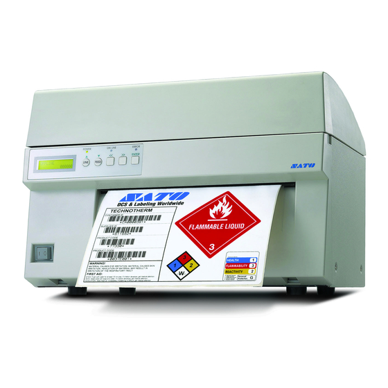
SATO M10e Operator's Manual
Thermal transfer printer
Hide thumbs
Also See for M10e:
- Operation manual (52 pages) ,
- Parts list (40 pages) ,
- Quick manual (10 pages)
Table of Contents
Advertisement
Advertisement
Table of Contents

Related Manuals for SATO M10e


Summary of Contents for SATO M10e
- Page 1 M10e Thermal Transfer Printer OPERATOR MANUAL PN 9001101 Rev. A...
- Page 2 All rights reserved. No part of this document may be reproduced or issued to third parties in any form whatsoever without the express permission of SATO America, Inc. The materials in this document is provided for general information and is subject to change without notice. SATO America, Inc.
-
Page 3: Table Of Contents
Section 5. Troubleshooting Initial Checklist...5-1 Using the IEEE1284 Parallel Interface ...5-1 Using the RS232C Serial Interface ...5-2 Using The Universal Serial Bus (USB) Interface ...5-3 Using the Lan Ethernet Interface ...5-3 Error Signals ...5-6 SATO M10e PN 9001101 Rev. A... - Page 4 BiDirectonal Communications ...6-8 Section 7. Label Sheet Commands Label Size ...7-2 Label Start...7-3 Label Format...7-4 SLabel Variable Data...7-5 Label Print Quantity...7-6 Section 8. Optional Accessories PCMCIA Memory Cards ...8-1 Plug-in Interface Modules ...8-2 Cutter ...8-3 PN 9001101 Rev. A SATO M10e...
-
Page 5: Section 1. Printer Overview
The M10e is available in two versions. The M10eDT is a direct thermal only version and must use thermally sensitive paper to print. The M10eTT is a thermal transfer model and has provisions for using a thermal transfer ribbon. -
Page 6: Specifications
Fixed, 0.9 in. (22.5 mm) left of center Fixed, 0.2 in. (5 mm) from left label edge Not Used 6.5 in. (165 mm), 8.7 in. (220 mm), 10.7 in.(273 mm) 984 ft. (300 m) 4.5 micron, Wound Face-In PN 9001101 Rev. A SATO M10e... - Page 7 Universal Serial Bus Ethernet PROCESSING Flash ROM SDRAM Receive Buffer Memory Expansion (1) Only one interface module can be installed in a printer at a time. SATO M10e M10e Green LED Green LED Red LED 2 Line x 16 Character...
- Page 8 CG Trimvirate®, 8 pt to 72 pt Bit Mapped TrueType® Fonts with Utility Program Expansion to 12X in either X or Y coordinates Character Pitch control Line Space control Journal Print facility 0°, 90°, 180° and 270° Rotation PN 9001101 Rev. A SATO M10e...
- Page 9 0°, 90°, 180° and 270° Rotation Sequential numbering of both numerics and bar codes RAM storage for custom designed characters Dot addressable, SATO Hex/Binary, BMP or PCX formats Overlay of predesigned forms in image buffer PN 9001101 Rev. A Section 1: Overview...
- Page 10 Autoswiching 100-240 VAC +/-10%, 60 Hz 560W Operating, 40W Idle 41° to 104°F (5° to 40°C) (-5° to 60°C) 30 to 90% RH Non-Condensing 30 to 80% RH Non-Condensing UL, CSA, TUV FCC Class B PN 9001101 Rev. A SATO M10e...
- Page 11 COAX/TWINAX Coan/Twinax Plug-In Interface module. Coax interface emmulates an IBM INTERFACE 3287-2 printer with a stndard Type A BNC connector. Twinax interface emulates IBM 5224, 5225, 5226 or 4214 printers with auto-terminate/cable through capabilities. PARALLEL INTERFACE IEEE1284 Bi-Directional Plug-In Interface Module...
- Page 12 Section 1: Overview This page left intentionally blank. Page 1-8 PN 9001101 Rev. A SATO M10e...
-
Page 13: Section 2. Installation
INTRODUCTION This section of the manual has been written to help you install the SATO M10e printers and to get started as quickly as possible. It is recommend to read each chapter in this manual before the installation or the use of the print modules. -
Page 14: Dimensions
Section 2. Installation DIMENSIONS Width: Depth: Height:, M10eTT: Height, M10eDT Page 2-2 18.7 inches 475 mm 12.3 inches 313.4 mm 12.6 inches 319.2 mm 10.8 inches 274.2 mm PN 9001101 Rev. A SATO M10e... -
Page 15: Components
COMPONENTS Operator Panel Power Switch Left Ribbon Supply Spindle Left Ribbon Take Up Spindle Empty Ribbon Core SATO M10e LCD Panel Paper Exit PN 9001101 Rev. A Section 2. Installation Top Cover Spring Loaded Ribbon Supply Spindle Spring Loaded RibbonTake Up... - Page 16 To turn power On or Off To set up the various configurations and to display dispensing quantity and the various alarms. Potentiometers and DIP switches to configure the printer and make setup adjustments. To input 115V 50/60 Hz. Use the power cable provided.
-
Page 17: Media Loading
10. Manually wind approximately three turns of ribbon on the core. 11. Inspect the ribbon to make sure it is not folded over or excessively wrinkled as it passes over the print head. SATO M10e Load ribbon supply Ribbon Supply Core Center Justified Ribbon... - Page 18 “PUSH” until the Print Head latches firmly in place. Loading the Label Stock The M10e has an automatic media loading feature, making it extremely easy to load. 1. Select the proper media sensing method using the DIP switches on the Configuration Panel.
-
Page 19: Label Sensing
LABEL SENSING The M10e can position labels using either a label gap (transmissive) or an Eye-Mark (reflective) sensor. The sensor used is selected by DSW2-2. The sensor position are fixed and cannot be adjusted. In addition, the signals from the sensors can be adjusted using the LCD panel to compensate for different liner opacities and/or Eye-Mark reflectance values. -
Page 20: Operation Panel
Illuminated when errors have occurred. Illuminated when printer is On-Line. Switches the printer On-Line or Off-Line. It can also be used as a Pause function key to stop label during the printing process. Also used as an UP cursor control. -
Page 21: Dip Switch Panel
The DIP Switch panel is located inside the cover and contains two 8-position DIP switches and three adjustment potentiometers. Adjustment procedures for these are listed in Section 3: Configuration. Pitch Display SATO M10e Print Offset PN 9001101 Rev. A Section 2. Installation... - Page 22 Section 2. Installation This lage left intentionally blank. Page 2-10 PN 9001101 Rev. A SATO M10e...
-
Page 23: Section 3. Configuration
They will not become effective until the power is cycled. RS232 TRANSMIT/RECEIVE SETTING Data Bit Selection (DSW1-1). This switch sets the printer to receive either 7 or 8 bit data bits for each byte transmitted. DSW1-1... - Page 24 Print Mode Selection (DSW2-1). Selects between direct thermal printing on thermally sensitive paper and thermal transfer printing using a ribbon. DSW2-1 SETTING Therm Xfr Direct Therm Page 3-2 DSW1 DSW1 SETTING 9600 19200 38400 57600 DSW1 SETTING Rdy/Bsy Xon/Xoff Bi-Com 3 Bi-Com 4 DSW2 PN 9001101 Rev. A SATO M10e...
- Page 25 Sensor Type Selection (DSW2-2). Selects between the use of a label gap or a reflective Eye- Mark detector. DSW2-2 SETTING Eye-Mark Head Check Selection (DSW2-3). When selected, the printer will check for head elements that are electrically malfunctioning. DSW2-3 SETTING Disabled Enabled Hex Dump Selection (DSW2-4).
- Page 26 Section 3. Configuration Firmware Download (DSW2-6). Places the printer in the Firmware Download mode for downloading new firmware into flash ROM. DSW2-6 SETTING Disabled Enabled Protocol Code Selection (DSW2-7). Selects the command codes used for protocol control. Refer to page E-1 for more information.
- Page 27 DSW3-3 SETTING Not Used Sensor Used Back-Feed Selection (DSW3-4). When Back-Feed is enabled, the printer will position the last printed label for dispensing and retract it before printing the next label. The amount of backfeed offset is adjustable. DSW3-4 SETTING...
- Page 28 Repeat Print via External Signal (DSW3-8). Allows the applicator to reprint the current label in the print buffer. DSW3-8 SETTING Enabled Disabled Page 3-6 DSW1 SETTING Type 4 Type 3 Type 2 Type 1 DSW3 PN 9001101 Rev. A SATO M10e...
-
Page 29: Default Settings
These settings are stored in non- volatile memory and are not affected by powering the printer off. The printer may be reset to use the default software settings by depressing the LINE and FEED keys simultaneously while powering the printer on. -
Page 30: Potentiometer Adjustments
1. While depressing the FEED key on the front panel, power the printer on. 2. When you hear one beep from the printer, release the FEED key and the printer will display on the LCD panel a message asking what type of Test Label you want to print. - Page 31 NOTE: The PRINT potentiometer adjustment will affect the darkness in all of the command code speed and darkness ranges. SATO M10e PN 9001101 Rev. A Page 3-9...
-
Page 32: Lcd Panel Printer Configuration
If you load a label job that includes software settings and then enter a new setting via the LCD panel, the manually set values will be used by the printer. - Page 33 The print speed selections are dependent upon the printer model. The current setting is indicated by the cursor. 1. Use the Cursor keys to step the cursor to the desired setting.
- Page 34 Page 3-12 The label Pitch is the distance from the leading edge (the edge that comes out of the printer first) of a label and the leading edge of the next label. The leading edge position of the label can be adjusted relative to the print head +/- 59mm in increments of 1mm.
- Page 35 ADVANCED MODE An Advanced Mode is provided to make adjustments that require only occasional changes. Since they affect the basic operation of the printer, the procedure for entering this mode is designed to prevent someone from accidently changing the settings.
- Page 36 Note: This setting can be overriden by the Base Reference Point Command. The Calendar is a optional feature in the M10e printer allowing the date and time to be set manually using the LCD Display or via the <ESC>WT Calendar Set command. This screen will not be displayed if the Calendar Option is not installed.
- Page 37 Ignore CR/LF selection. This selection tells the printer to strip out all carriage return/line feed pairs (CR/LF ) from the data stream, including graphics and 2D bar codes. It is used primrily to maintain compatibility with earlier models of SATO printers.
- Page 38 Advanced Mode display. To exit the Advanced mode, power the printer off and then back Displays the firmware during the initialization. The Card Mode is entered from the Advanced Mode display by pressing the Right Cursor key (>>)once.
- Page 39 Mem Full Error Indicates that there is insufficient memory available. This selection allows you to copy SATO fonts from the PCMCIA Memory card installed in the Memory Card slot on the rear of the printer to the optional Flash ROM.
- Page 40 This selection allows you to copy the entire contents of the optional Expanded Memory to the PCMCIA Memory card installed in the Memory Card slot on the rear of the printer. 1. Use the Cursor keys to step the cursor to desired setting. If Yes is selected, the printer will enter the Card Copy mode.
- Page 41 PCMCIA Memory Card. 1. Use the Cursor keys to step the cursor to desired setting. If Yes is selected, the printer will enter the Card Copy mode. If No is selected, the display will advance to the mode display.
- Page 42 The Service Mode display indicates that the printer is in the Card Mode. To advance to the first selection, press the ENTER key. The M10e printers determine the location of the leading edge of the label by measuring the difference between light levels when it sees either a label edge or a black “EYE”...
- Page 43 4. Use the LINE and FEED keys to step the counter to the desired setting. The reading will advance to a setting of 4.9 (the maximum voltage). If a value of “0.0” is set, the printer will automatically set the level each time the printer is powered on with labels loaded and the head is closed.
- Page 44 4. Use the LINE and FEED keys to step the counter to the desired setting. The reading will advance to a setting of 4.9 (the maximum voltage). If a value of “0.0” is set, the printer will automatically set the level each time the printer is powered on with labels loaded or the head is closed.
- Page 45 Pin 9 of the EXT connector to be true. If Mode1 is selected, pin 9 will be true when the printer is ready to print, i.e. it is Online and has a print job loaded (a quantity of labels to be printed on the display).
- Page 46 This will correctly position the next printed label under the print head. If Disable is selected, the printer will not try to detect the next label and the operator is responsible for ensuring that the label is correctly positioned before printing.
- Page 47 The Test Print Mode offers 4 different status labels for troubleshooting. If DSW3-5 is in the OFF position, the Test Print cycle must be initiated with a Print Start signal on the EXT connector You enter the Test Print Mode by pressing the FEED key while powering the printer on..
- Page 48 STOP PRINTING DEFAULT SETTING MODE Occassionally it is desirable to reset all printer configuration settings to their original default conditions. This allows the operator to start reconfiguration of the printer starting from a know set of conditions. V 05.00.03.00 INITIALIZING...
- Page 49 V 05.00.03.00 INITIALIZING ALT.PROTOCOL DEFAULT COMPLETE DOWNLOAD USER DEFINED PROTOCOL CODES The user can define a set of custom protocol codes and download them to the printer using the <ESC>LD command. V 05.00.03.00 INITIALIZING USER DOWNLOAD PRESS THE LINE KEY SATO M10e 3.
- Page 50 USER DOWNLOAD WAITING HEX DUMP MODE In addition to the Test Print Labels, the printer can print the contents of the receive buffer in a hexadecimal format to allow the data stream to be examined for errors and troubleshooting. V 05.00.03.00...
-
Page 51: Section 4. Cleaning And Maintenance
• Replacing the Fuse ADJUSTING THE PRINT QUALITY One of the nice features of the SATO printers are their high print quality. They are equipped with two different methods of adjusting the quality of the print; print darkness and speed. -
Page 52: Cleaning The Print Head, Platen And Rollers
This adjustment is made only on an individual label basis using the Print Speed command code. For more details on this command, see the “e” Printer Programming Reference. Changing the print speed allows the user to control the amount of time allowed for print element cooling before the media is stepped to the next print position. -
Page 53: Cleaning The Label Edge And Paper End Sensors
4. Lift up on both ends of the Label Cover Plate at the points marked with the purple arrows until it releases. 5. Apply SATO Thermal Print Head Cleaner to one of the cotton swabs. 6. The Platen is the rubber roller directly below the Print Head. - Page 54 Eye-Mark passes through the beam, the light is no longer reflected back to the sensor detector, indicating to the printer that it should use this position as the start of a new label. When dust, dirt, adhesive or other foreign matter interferes with the light path of either of these sensors, the results is erratic label positioning and feeding.
-
Page 55: Cleaning The Auto Load Sensor
4. Lift up on both ends of the Label Cover Plate at the points marked with the purple arrows until it releases. 5. Apply SATO Thermal Print Head Cleaner to one of the cotton swabs. 6. The sensor is located underneath the label plate.. -
Page 56: Replacing The Print Head
REPLACING THE PRINT HEAD The print head is a user-replaceable item. If it becomes damaged for any reason, it can be easily removed and replaced. Contact your local SATO representative for information on obtaining a new print head. Supplies needed: Flat Blade Screwdriver (Note: Some units may require a No. 2 Phillips screwdriver) 1. -
Page 57: Section 5. Troubleshooting
TROUBLESHOOTING This section has been devised to help you if you are unable to produce output on the M10e printers. Use this section to make sure the basics have been checked before deciding you are unable to proceed any further. The section is divided into five parts: •... -
Page 58: Using The Rs232C Serial Interface
Section 6: Interface Specifications. 3. Is the RS232 Interface Module installed in the printer? The M10e printers require the new Hi Speed Serial Interface (PN WCL40451)to take advantage of the faster data transmission speeds. -
Page 59: Using The Universal Serial Bus (Usb) Interface
2. Within the new Window you should have an Icon listed as System. Double Click on this. 3. Click on the Device Manager tab. 4. Make sure that the View Device by type is checked. Scroll down until you get to SATO- USB device. -
Page 60: Checking The Network Connection And Cabling
Checking the Interface between the Print Server and the Printer First make sure that the cable between the print server and the printer is securely plugged in at both sides. Then: 1. Wait about two minutes after the printer is powered on and then run a printer self-test (see Secton 3:Configuration for information on how to run the self-test). - Page 61 Section 5. Troubleshooting 2. Check the individual protocol troubleshooting sections provided with the Ethernet Plug-In Interface Module for additional causes of intermittent printer problems. SATO M10e PN 9001101 Rev. A Page 5-5...
-
Page 62: Error Signals
2. Paper incorrectly loaded. 1. Needs new ribbon roll. 2. Ribbon sensor needs adustment. 1. Read/Write error. 2. Corrupted download file. 3. Download file too large. 1. R/W error during copying. 2. Card not installed properly. 3. File too large. SATO M10e... -
Page 63: Section 6. Interface Specifications
INTERFACE SPECIFICATIONS INTRODUCTION The M10e printer utilize a Plug-In Interface Module for maximum printer configuration flexibility. This section presents the interface specifications for the M10e printer. These specifications include detailed information on how to properly interface your printer with your host system. -
Page 64: The Receive Buffer
THE RECEIVE BUFFER The M10e printers have the ability to receive a data stream from the host in one of two ways. The receive buffer may be configured to accept one print job at a time or multiple print jobs. -
Page 65: Ieee1284 Parallel Interface
X-On is sent to tell the host that it can again receive data. All printer error conditions (i.e., label out, ribbon out) will cause the printer to go busy (DTR “low” or X-Off) until the problem is corrected and the printer is placed on-line. The printer will also be busy if taken off-line from the front panel. - Page 66 <ESC>A . . Job#1 . . <ESC>Z<ESC>A . . Job#n . . <ESC>Z Page 6-4 AMP 57-40360 (DDK) or equivalent AMP 57-30360 (DDK) or equivalent IEEE1284 Parallel, 10 ft. (3 m) or less High = +2.4V to +5.0V Low = 0V to -0.4V PN 9001101 Rev. A SATO M10e...
-
Page 67: Rs232 Serial Interface
Asynchronous ASCII Data Transmission Rate Character Format ELECTRICAL SPECIFICATIONS Connector DB-25S (Female) Cable Signal Levels SATO M10e Section 6. Troubleshooting Half-duplex communication Ready/Busy Hardware Flow Control Pin 20, DTR Control Pin 4, RTS Error Condition X-On/X-Off Software Flow Control Bi-Directional Communication... - Page 68 Section 6. Troubleshooting PIN ASSIGNMENTS Page 6-6 PN 9001101 Rev. A SATO M10e...
- Page 69 CABLE REQUIREMENTS READY/BUSY FLOW CONTROL Ready/Busy is the hardware flow control method for the serial interface on the M10e printers. By raising/lowering the voltage level on Pin 20 of the RS232C port, the printer notifies the host when it is ready to receive data. Pin 4 (RTS) and pin 20 (DTR) are the important signals on the printer for this method of flow control.
-
Page 70: Universal Serial Bus (Usb) Interface
The Universal Serial Bus (USB) interface is a Plug-In Interface Module that can be installed by the user. It requires a driver (shipped with each printer that has the interface installed) that must be loaded on your PC and the PC must be configured to support USB peripherals using Windows 98 or above. - Page 71 One way to ensure these pins are always in the correct state is to tie pin 20 (DTR) to pin 6 (DSR) and pin 4 (RTS) to pin 5 (CTS) at the printer end of the cable.
- Page 72 ACK (06 hexadecimal) is returned if there are no errors and a NAK (16 hexadecimal) if a printer error exists. Note:To provide compatibility with older SATO printers, the RS232C interface can be configured to use an earlier Bi-Com 3 ENQ/ACK/NAK protocol selected via DSW2-8 and DSW1-7/8 (on the RS232 Interface module).The earlier protocol did not have...
-
Page 73: Section 7. Label Sheet Commands
SECTION 7. LABEL SHEET COMMANDS The wide carriage M10e makes it an ideal replacement for sheet fed printers. Thses commands facilitate the printing lf sheets of small labels. SATO M10e PN 9001101 Rev. A Page 7-1... -
Page 74: Label Size
Media Size command; the format specification <ESC>_N command and the <ESC>_D Variable Data command will be ignored. lated from the width specified in the “bbbb” label size specified. PN 9001101 Rev. A Cut position (when d=2) A1 command and the <ESC> SATO M10e... -
Page 75: Label Start
<ESC>_<ESC>Q,1 <ESC>Z PRINTER OUTPUT The printer will print the label data following the command. Special Notes 2. You must specify the print noumber of small label with the small label 3. Do not specify the register command after the small label start specifi- SATO M10e Section 7. -
Page 76: Label Format
<ESC>_D,01,CCCC<ESC>_D,02,*44444*<ESC>_D,03,44<ESC>_Q,4 <ESC>Z PRINTER OUTPUT The printer will print 1 label defines by the first <ESC>_N command, 2 labels defined by the second and 4 labels defined by the third. Special Notes 1. The selectable range for format setting <ESC>_N is limited to characters 2. -
Page 77: Slabel Variable Data
4 with the data specified according to the third. Special Notes 1. 1. When the Variable Data command <ESC>_D is omitted, the default c 2. However, when the variable data specified matches that specified by th SATO M10e Section 7. Label Sheet Commands Field number, 01-99 n...nn Variable data, number of characters defined in the <ESC>_N command... -
Page 78: Label Print Quantity
Number of labels to be printed, 0001-9999 Number of blank labels following the number of labels to be printed (may be omitted) 1-9 <ESC>_Q,1,0 Following the data specified in the <ESC>_F or <ESC>_D commands. aaaa=0001, b=0 PN 9001101 Rev. A SATO M10e... -
Page 79: Section 8. Optional Accessories
• PCMCIA Memory Cards • Cutter PCMCIA MEMORY CARDS DESCRIPTION The Memory Card Option provides the connectors and interface board for one PCMCIA memory cards slots. The printer memory can be expanded up to 16MB. Type Applicable Specifications Size Connector Pins... -
Page 80: Plug-In Interface Modules
Rear Panel and is retained by two screws. Use the following procedure to replace an interface molule. 1. Turn power off both the printer and the host and remove the power and interface cables. WARNING: Never connect or disconnect interface cables (or use a switch box) with power applied to either the host or the printer. -
Page 81: Cutter
Section 8. Optional Accessories CUTTER To be added SATO M10e PN 9001011 Rev. A Page 8-3... - Page 82 Section 8. Optional Accessories This page left intentionally blank. Page 8-4 PN 9001011 Rev. A SATO M10e...