Table of Contents
Advertisement
Quick Links
Advertisement
Table of Contents

Related Manuals for Pentair FLECKXT


Summary of Contents for Pentair FLECKXT
- Page 1 FLECK XT SERVICE MANUAL www.pentairaqua.com...
-
Page 2: Table Of Contents
TABLE OF CONTENTS IMPORTANT PLEASE READ: • The information, specifications and illustrations in this JOB SPECIFICATION SHEET ..........3 manual are based on the latest information available at TIMER OPERATION ..............4 the time of printing. The manufacturer reserves the right MASTER PROGRAMMING MODE FLOW CHART ....6 to make changes at any time without notice. -
Page 3: Job Specification Sheet
JOB SPECIFICATION SHEET 12. Regeneration Time: Some options may not be available depending on NOTE: Regeneration Cycle Step #1: _ _ : _ _ : _ _ valve model or other options chosen. Regeneration Cycle Step #2: _ _ : _ _ : _ _ Circle and/or Fill in the Appropriate Data for Future Reference: Regeneration Cycle Step #3: _ _ : _ _ : _ _ Regeneration Cycle Step #4: _ _ : _ _ : _ _... -
Page 4: Timer Operation
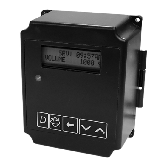
TIMER OPERATION Regeneration A time initiated control valve regenerates when the number of programmed days has been reached. A flow initiated control valve regenerates when the volume count is zero or is below reserve capacity. System Type Regeneration Trigger Time Clock A) Day override parameter is reached and Delayed B) the time of day matches the regeneration day... - Page 5 TIMER OPERATION CONTINUED Flow Meter Equipped Timer As treated water is used, the Volume Remaining display Manually Initiating a Regeneration counts down from the calculated system capacity, less the reserve volume. Once capacity reaches zero or reserve, if the 1. When timer is in service, press the Extra Cycle button for 5 immediate system the unit will regenerate immediately.
-
Page 6: Master Programming Mode Flow Chart
MASTER PROGRAMMING MODE FLOW CHART Depending on current option settings, some displays NOTE: cannot be viewed or set. Before entering Master Programming, please CAUTION contact your local professional water dealer. To Set Time of Day 1. Press and hold the Up or Down buttons for 2 seconds. 2. - Page 7 MASTER PROGRAMMING MODE FLOW CHART CONTINUED FLECK • 7 XT Service Manual...
-
Page 8: Master Programming Mode
MASTER PROGRAMMING MODE 3. Regenerant Flow This program step selects how the regenerant flows through When the Master Programming Mode is entered, parameters the tank (must match cam). The selections available will vary can be set to make the timer function as needed. depending on the previously chosen valve model. - Page 9 MASTER PROGRAMMING MODE 11. Regeneration Cycle Step Programming This program step programs the Regeneration Cycle step CONTINUED times 1 through 5. Please refer to the chart below for regenerant flow default cycle steps and times. 8. Volume Override This program step is used to set the volume override of the unit. •...
- Page 10 MASTER PROGRAMMING MODE 16. Flow Meter Size This program step sets the size of the flow meter. CONTINUED • Press the Up or Down buttons to adjust this value. 14. Brine Line Flow Control Size • Press the Extra Cycle button. This program step allows the selection of the desired brine line flow control size in the unit (must match physical brine line flow control).
-
Page 11: User Programming Flow Chart & Mode
USER PROGRAMMING FLOW CHART DIAGNOSTIC PROGRAMMING MODE FLOW & MODE CHART Depending on current option settings, some displays Depending on current option settings, some displays NOTE: NOTE: cannot be viewed or set. cannot be viewed or set. Entering User Mode Entering Diagnostic Mode: Press and hold the Up and Down buttons for 5 seconds at any 1. -
Page 12: Diagnostic Programming Mode
DIAGNOSTIC PROGRAMMING MODE 6. Volume Remaining This program step displays the volume remaining. The timer Depending on current option settings, some displays NOTE: will regenerate if the volume remaining is set to zero. The cannot be viewed. maximum ranges are the same as the maximum volume Overview Diagnostic Mode calculated on the main screen. -
Page 13: 2510/2750/2850 Power Head Assy
2510/2750/2850/2850S POWER HEAD ASSY 61501-3200XT-2_2750XT_2850XT_REVA FLECK • 13 XT Service Manual... - Page 14 2510/2750/2850 POWER HEAD ASSY CONTINUED Item No. Part No. Description 29 ....1 ..41102 ....Label, 3900NT, Ground 1 ....1 ..18697-15 ..Backplate, Hinged 30 ....1 ..10269 ....Nut, Jam, 3/4 - 16 2 ....1 ..60219-02 ..Cover Assy, Environmental, 31 ....1 ..10712 ....Fitting, Brine Valve Black w/Clear Window 32 ....1 ..
-
Page 15: 2900S Power Head Assy
2900S POWER HEAD ASSY 61501-3200XT_2900XT_REVA FLECK • 15 XT Service Manual... - Page 16 2900S POWER HEAD ASSY CONTINUED Item No. Part No. Description Item No. Part No. Description 1 ....1 ..18697-15 ..Backplate, Hinged 35 ....1 ..11381 ....Pin, Roll, 2900/3900 2 ....1 ..60219-02 ..Cover Assy, Environmental, 36 ....1 ..14759 ....Link, Piston Rod Black 37 ....1 ..
-
Page 17: 3150 Power Head Assy
3150 POWER HEAD ASSY 61501-3200XT_3150XT_REVA FLECK • 17 XT Service Manual... - Page 18 3150 POWER HEAD ASSY CONTINUED Item No. Part No. Description Item No. Part No. Description 1 ....1 ..19304-04 ..Backplate, 3150/3900 Upper 36 ....1 ..19121 ....Meter, Cable Assy, 3200NT 2 ....1 ..15120 ....Bracket, Motor Mtg, ..19121-08 ..Meter Cable Assy, NT, 3150/3900 35-inch w/Connector 3 ....1 ..
-
Page 19: 3900 Power Head Assy
3900 POWER HEAD ASSY 61501-3200XT_3900XT_REVA FLECK • 19 XT Service Manual... - Page 20 3900 POWER HEAD ASSY CONTINUED Item No. Part No. Description Item No. Part No. Description 1 ....1 ..19304-04 ..Backplate, 3150/3900 Upper 38 ....1 ..19121 ....Meter, Cable Assy, 3200NT 2 ....1 ..15120 ....Bracket, Motor Mtg, ..19121-09 ..Meter Cable Assy, NT, 3150/3900 99.5-inch 3 ....1 ..
-
Page 21: 9000/9100/9500 Power Head Assy
9000/9100/9500 POWER HEAD ASSY 61501-3200XT-9_REVA FLECK • 21 XT Service Manual... - Page 22 9000/9100/9500 POWER HEAD ASSY CONTINUED Item No. QTY Part No. Description 1 ....1 ..17784-05 ..Panel, Control, 9000/9500, ET 2 ....1 ..15175 ....Label, Shaft Position 3 ....3 ..15209 ....Pin, Roll, 1/8 x 1/2 SS 4 ....2 ..15367 ....Pin, Dowel, 9000 5 ....1 ..
-
Page 23: Wiring Diagrams
WIRING DIAGRAMS Single Piston FLECK • 23 XT Service Manual... - Page 24 WIRING DIAGRAMS CONTINUED Dual Piston 24 • FLECK XT Service Manual...
-
Page 25: Troubleshooting
TROUBLESHOOTING Error Display Screen Examples Timer If an error is detected, an error screen will alternate with the main display screen every few seconds, and the LED light will be red. During an error condition, the unit continues to monitor the flow meter and update the remaining capacity. - Page 26 26 • FLECK XT Service Manual...
- Page 27 FLECK • 27 XT Service Manual...
- Page 28 All Pentair trademarks and logos are owned by Pentair, Inc. or its affiliates. All other registered and unregistered trademarks and logos are the property of their respective owners. Because we are continuously improving our products and services. Pentair reserves the right to change specifications without prior notice.