Baldor Flex+DriveII Installation Manual
Servo controls
Hide thumbs
Also See for Flex+DriveII:
- Operating manual (42 pages) ,
- Reference manual (20 pages) ,
- Installation manual (166 pages)

Related Manuals for Baldor Flex+DriveII


Summary of Contents for Baldor Flex+DriveII
- Page 1 SERVO DRIVE FlexDrive / Flex+Drive Servo Controls Installation Manual 10/02 MN1902...
-
Page 3: Table Of Contents
......... 3-16 3.5.2 Motor power cable pin configuration - Baldor BSM rotary motors ..3-16 3.5.3... - Page 4 ......4-16 4.4.6 Connecting Baldor HMI Operator Panels ......4-17 Connection summary - minimum system wiring .
- Page 5 WorkBench v5 ......... . 5.2.1 Help file .
- Page 6 Appendices A Accessories ........Introduction .
-
Page 7: General Information
This manual is copyrighted and all rights are reserved. This document or attached software may not, in whole or in part, be copied or reproduced in any form without the prior written consent of Baldor. Baldor makes no representations or warranties with respect to the contents hereof and specifically disclaims any implied warranties of fitness for any particular purpose. - Page 8 Product notice Only qualified personnel should attempt the start-up procedure or troubleshoot this equipment. This equipment may be connected to other machines that have rotating parts or parts that are controlled by this equipment. Improper use can cause serious or fatal injury. Only qualified personnel should attempt to start-up, program or troubleshoot this equipment.
- Page 9 WARNING: Be sure all wiring complies with the National Electrical Code and all regional and local codes. Improper wiring may result in unsafe conditions. WARNING: The stop input to this equipment should not be used as the single means of achieving a safety critical stop.
- Page 10 CAUTION: Do not connect AC power to the drive terminals U, V and W. Connecting AC power to these terminals may result in damage to the drive. CAUTION: Baldor does not recommend using “Grounded Leg Delta” transformer power leads that may create earth/ground loops and degrade system performance. Instead, we recommend using a four wire Wye.
-
Page 11: Introduction
DeviceNet or Profibus connectivity. See Appendix A for details about options. FlexDrive will operate with a large number of brushless servo motors - for information on selecting Baldor servo motors, please see the sales brochure BR1202 (BR1800 for linear motors) available from your local Baldor representative. -
Page 12: Receiving And Inspection
The catalog number is marked on the front of the unit, just below the Baldor logo. It is a good idea to look for the catalog number (sometimes shown as ID/No: ) and write it in the space provided here:... -
Page 13: Units And Abbreviations
2.3 Units and abbreviations The following units and abbreviations are used in this manual: ....Volt (also VAC and VDC) ....Watt . - Page 14 2-4 Introduction MN1902...
-
Page 15: Basic Installation
Basic Installation 3.1 Introduction You should read all the sections in Basic Installation to ensure safe installation. This section describes the mechanical and electrical installation of the FlexDrive in the following stages: Location considerations Mounting the FlexDrive Connecting the AC power supply Connecting the optional customer supplied 24VDC control supply Connecting the motor Installing a regeneration resistor (Dynamic Brake resistor) -
Page 16: Rs485 / Rs422 Systems
Note: The serial connector on the FlexDrive (connector X6) can be configured as either RS232 or RS485 / RS422. Pin 9 is used to carry +8V for powering some Baldor keypad peripherals. Ensure that pin 9 is not connected to earth/ground or to equipment that could be damaged by the +8V supply. -
Page 17: Other Information Needed For Installation
3.1.5 Other information needed for installation This information is useful (but not essential) to complete the installation: The data sheet or manual provided with your motor, describing the wiring information of the motor cables/connectors Knowledge of which digital inputs/outputs will be ‘Active Low’, ‘Active High’ or edge triggered. -
Page 18: Mechanical Installation And Location Requirements
3.2 Mechanical installation and location requirements It is essential that you read and understand this section before beginning the installation. CAUTION: To prevent equipment damage, be certain that the input power has correctly rated protective devices installed. CAUTION: To prevent equipment damage, be certain that input and output signals are powered and referenced correctly. -
Page 19: Mounting The Flexdrive
For effective cooling and maintenance, the FlexDrive should be mounted on a smooth, non-flammable vertical surface. The power handling capability is affected by the temperature of the left side of the unit. At least 50mm (2 in) top and bottom clearance of the FlexDrive must be provided for airflow. -
Page 20: Dimensions
3.2.2 Dimensions 65mm Package size H only. Mounting keyhole and slot detail FRONT PANEL A 5mm (package sizes E, G and H: 6.5mm) B 10mm (package sizes E, G and H: 12mm) C 9mm (package sizes E, G and H: 10mm) Package sizes E, G &... -
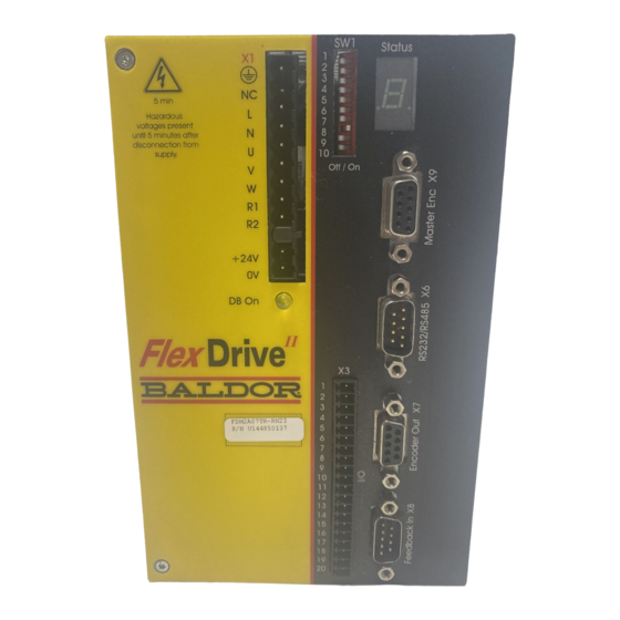
Page 21: Connector Locations
3.3 Connector locations X1 / X1A Power X9 Master Encoder Encoder Pulse & Dir. Single-phase models CHA+ Pulse+ CHB+ Dir.+ Earth CHZ+ (NC) (NC) (NC) (NC) AC Line DGND (NC) AC Neutral CHA- Pulse GND Motor U CHB- Dir. GND Motor V CHZ- (NC) -
Page 22: Power Connections
Only class 1 wiring should be used. Baldor drives are designed to be powered from standard single and three-phase lines (depending on model) that are electrically symmetrical with respect to earth/ground. Due to the importance of system earthing/grounding for increased reliability, earthing/grounding methods are shown in sections 3.4.1 and 3.4.2. -
Page 23: Single-Phase Connection To Package Sizes A, B, C, D
3.4.1 Single-phase connection to package sizes A, B, C, D Location Connector X1 (Mating connector: Phoenix COMBICON MVSTBW 2,5/9-ST, 5mm pitch) Part number FDH1A... / FPH1A... FDH2A... / FPH2A... Nominal input 115VAC, 1Φ line to neutral 230VAC, 1Φ line to neutral voltage Range 97-125VAC 220-250VAC... -
Page 24: Three-Phase Connection To Package Sizes E, G, H
3.4.2 Three-phase connection to package sizes E, G, H Location Connector X1A (Mating connector: Phoenix POWER COMBICON PC4/..-ST- 7.62) Part number FDH2A15... / FPH2A15... FDH4A... / FPH4A... Nominal input 230VAC, 3Φ line to line 230-460VAC, 3Φ line to line voltage Range 184-253VAC 180-528VAC... -
Page 25: Input Power Conditioning
3.4.3 Input power conditioning Baldor drives are designed for direct connection to standard single and three-phase lines (depending on model) that are electrically symmetrical with respect to earth/ground. Certain power line conditions must be avoided; an AC line reactor, an isolation transformer or a step... -
Page 26: Power Supply Filters
3.4.5 Power supply filters To comply with EEC directive 89/336/EEC, an AC power filter of the appropriate type must be connected. This can be supplied by Baldor and will ensure that the FlexDrive complies with the CE specifications for which it has been tested. Table 1 lists the appropriate filters:... -
Page 27: Wire Sizes And Protection Device Ratings
3.4.6 Wire sizes and protection device ratings Table 2 describes the wire size to be used for power connections and the ratings of the protection devices. Incoming Power Nominal Continuous D-Type Time Minimum Minimum Input Input Output Output Input Input Delay Delay Wire Gauge... -
Page 28: External Customer Supplied 24V Control Supply
24V supply is provided for the FlexDrive . If other devices are likely to be powered from the same 24V supply then a filter (Baldor catalog number FI0014A00) should be installed to isolate the FlexDrive from the rest of the system. -
Page 29: Motor Connections
3.5 Motor connections The motor can be connected directly to the FlexDrive or through a motor contactor (M-Contactor). Location Connector X1 / X1A FDH1A... FDH2A... FDH2A15... FDH4A... Part number FPH1A... FPH2A... FPH2A15... FPH4A... Nominal output voltage 160VDC 320VDC 320VDC 565/650V Output voltage range 135-176VDC 306-350VDC 258-355VDC... -
Page 30: Motor Circuit Contactors
Ensure that shielding of the motor cable is continued on both sides of the contactor. 3.5.2 Motor power cable pin configuration - Baldor BSM rotary motors Figure 8 shows the pin configuration for a typical Baldor motor cable, part number CBL030SP-MHCE:... -
Page 31: Motor Cable Pin Configuration - Baldor Linear Motors
3.5.3 Motor cable pin configuration - Baldor linear motors The following table shows the pin colors used in a typical Baldor linear motor cable set, part number AY1763A00: Signal name Motor cable wire color Motor U Black Motor V Motor W... -
Page 32: Thermal Switch Connection
3.5.4 Thermal switch connection You might wish to wire the motor’s thermal switch contacts (normally open), using a relay, to a digital input on connector X3 (see section 4.3.1). Using the WorkBench v5 Digital I/O tool, the input can be configured to be the motor trip input. This allows the FlexDrive to respond to motor over-temperature conditions. -
Page 33: Motor Brake Connection
3.5.5 Motor brake connection You might wish to wire a motor’s brake, via relays, to digital outputs on connector X3 (see section 4.3.1). This provides a way for the Mint program to control the motor’s brake. A typical circuit is shown in Figure 10. from motor brake connections CGND... -
Page 34: Regeneration Resistor (Dynamic Brake Resistor)
3.6 Regeneration resistor (Dynamic Brake resistor) The 2.5A and 5A FlexDrive both have an internally fitted regeneration resistor *. For 7.5A, 15A, 20A and 27.5A FlexDrive , an external regeneration resistor must be installed to dissipate excess power from the internal DC bus during motor deceleration. Suitable regeneration resistors are listed in section A.1.7. -
Page 35: Feedback Connections
3.7 Feedback connections Two feedback options are available for use with linear and rotary motors - commutating encoder or resolver. Confirm the catalog number of your FlexDrive (see section 2.2.1) to ensure you are wiring the correct feedback device. There are some important considerations when wiring the feedback device: The feedback device wiring must be separated from power wiring. -
Page 36: Resolver Option - X8
WorkBench v5 Commissioning Wizard to provide 1024 ppr. The FlexDrive provides an input accuracy of ±3 counts. When used with a typical Baldor BSM series resolver motor the combined accuracy is ±11 counts (calculated with the input equivalent resolution set to the factory preset value of 4096 ppr). - Page 37 3.7.1.1 Resolver cable pin configuration Figure 12 shows the pin configuration for a typical Baldor resolver feedback cable, part number CBL030SF-ALCE. Signal name FlexDrive Motor / cable Baldor resolver cable X8 pin internal wire colors REF+ REF- Blue COS+ Green...
-
Page 38: Encoder Option - X8
3.7.2 Encoder option - X8 The encoder connections (ABZ channels and Hall signals) are made using the 15-pin D-type female connector X8. Twisted pair cables must be used for the complementary signal pairs e.g. CHA+ and CHA-. The overall cable shield (screen) must be connected to the metallic shell of the D-type connector. - Page 39 3.7.2.1 Encoder cable pin configuration - rotary motors Figure 14 shows the pin configuration for a typical Baldor encoder feedback cable, part number CBL030SF-KPCEA3. Signal name FlexDrive Motor / cable X8 pin CHA+ CHA- CHB+ CHB- CHZ+ CHZ- Hall U+...
- Page 40 CHA- CHB+ Please refer to MN1800 Linear Motors Please refer to MN1800 Linear Motors Installation & Operating Manual for details. CHB- CHZ+ CHZ- Baldor Hall cable internal wire colors Hall U+ White Hall V+ Hall W+ Black Brown Hall GND...
-
Page 41: Endat (Absolute Encoder) Option - X8
3.7.3 EnDat (absolute encoder) option - X8 The absolute encoder interface supports both incremental and absolute (multi and single turn) feedback using SinCos technology. It is possible to read and write information to the encoder. The absolute encoder connections are made using the 15-pin D-type female connector X8. Twisted pair cables must be used for the complementary signal pairs e.g. - Page 42 3.7.3.1 Absolute encoder cable pin configuration Figure 17 shows the pin configuration for a typical Baldor absolute encoder feedback cable, part number CBL030SF-KLCEA3. Signal name FlexDrive Motor / cable X8 pin Data - Sin A+ Cos B+ Clock- Clock +...
-
Page 43: Drive Enable - X3
3.8 Drive enable - X3 Location Connector X3, pins 7 & 9 (Mating connector: Phoenix MINI-COMBICON MC 1.5/20-ST-3,5) Name Drive enable Input voltage +24VDC (±20%) CREF 7 ENABLE 9 To enable the FlexDrive and allow motion, three actions are necessary: A customer supplied externally generated 24VDC supply must be connected between pins 7 and 9. -
Page 44: Drive Enable - Sw1 Dip Switch
3.8.2 Drive enable - SW1 DIP switch To enable the FlexDrive the front panel DIP switch 8 must be set to On. This switch provides a local enable/disable switch that can be useful during testing. The state of the drive enable DIP switch is displayed in the WorkBench v5 Spy window. -
Page 45: Dip Switches - Sw1
3.9 DIP switches - SW1 Various functions of the FlexDrive can be controlled by the front panel SW1 DIP switches. Location Switch block SW1 Switch Function Node number selection (serial and fieldbus networks) Node number selection (serial and fieldbus networks) Bit pattern values shown in italics 5 Hold 6 RS485 terminator... -
Page 46: Switch 5 - Hold
If switches 1-4 are all in the Off position, the Mint NODE keyword can be used to set the node number. WorkBench v5 (see section 5.2) reads the FlexDrive node number (during the scan process) and then uses it to direct commands to the FlexDrive Avoid accidentally setting switches 1-4 to the On position at the same time. -
Page 47: Switches 9 And 10 - Rs232/Rs485 Select
3.9.6 Switches 9 and 10 - RS232/RS485 select Switch 9 is reserved for Baldor keypad selection. Switch 10 selects RS232 communications (Off) or RS485/RS422 (On) the next time the FlexDrive is power-cycled. 3.9.7 Factory settings If switches 1-4 are all in the On position and switch 8 is set to Off, the FlexDrive... -
Page 48: Preventing A Program Running At Startup
3.9.8 Preventing a program running at startup Flex+Drive only: If switches 5 and 9 are set to On and switch 8 is set to Off, any program already in the Flex+Drive that contains an Auto command will be prevented from running automatically at startup. -
Page 49: Input / Output
Input / Output 4.1 Introduction This section describes the various digital and analog input and output capabilities of the FlexDrive , with descriptions of each of the connectors on the front panel. The following conventions will be used to refer to the inputs and outputs: . -
Page 50: Analog Input - X3 (Command)
4.2.1 Analog input - X3 (command) Connector X3, pins 1-3 Location (Mating connector: Phoenix MINI-COMBICON MC 1.5/20-ST-3,5) Name AIN0 Mint keyword ADC.0 Description Single ended or differential input. Common mode voltage range: ±10VDC. Resolution: 14-bit with sign (accuracy ±4.9mV) Common mode rejection: 40dB Input impedance: >5kΩ... - Page 51 AIN0+ AIN0+ AIN0 AIN0- AIN0 (ADC.0) (ADC.0) Differential connection Single ended connection Figure 23 - AIN0 analog input wiring +24VDC 1.5kΩ, 0.25W 1kΩ, 0.25W potentiometer AIN0 (ADC.0) Figure 24 - Typical input circuit to provide 0-10V (approx.) input from a 24V source MN1902 Input / Output 4-3...
-
Page 52: Relay Output - X3
4.2.2 Relay output - X3 Location Connector X3, pins 4 (+) & 5 (-) Name General purpose relay Mint keyword RELAY Description Relay switch contacts controlled by Mint, rated at 1A, 30VDC. Normally closed. Update interval: Immediate The factory preset assignment for the relay is as the global error output signal (see the Mint keyword GLOBALERROROUTPUT). -
Page 53: Digital I/O
4.3 Digital I/O The FlexDrive provides as standard: * 8 general-purpose inputs on connector block X3 3 general-purpose outputs on connector block X3 A digital input can be used to support many typical input functions: Error input Reset input Stop input Forward limit Reverse limit Interrupts (controlled from Mint) -
Page 54: Digital Inputs - X3
4.3.1 Digital inputs - X3 Location Connector X3 Pin Name Mint keyword 9 Drive Enable 10 DIN0 INX.0 CREF 7 11 DIN1 INX.1 12 DIN2 INX.2 13 DIN3 INX.3 14 DIN4 INX.4 15 DIN5 INX.5 16 DIN6 INX.6 17 DIN7 INX.7 Description Eight general-purpose optically isolated AC digital inputs. -
Page 55: Cref And Digital Inputs
4.3.2 CREF and digital inputs Pin 7 (CREF) controls the sense of all the digital inputs (X3 pins 9 to 17) and should be permanently wired, dependent on the user requirements: Active high: connect 0V to pin 7. The digital inputs will be active when a voltage of +24VDC (greater than 12VDC) is applied to them and will sink a current of approximately 5mA each. -
Page 56: Special Functions On Din4 And Din5 - Fast Inputs
4.3.4 Special functions on DIN4 and DIN5 - fast inputs Flex+Drive only: DIN4 and DIN5 can be configured using the FASTSELECT keyword to perform special functions: Fast interrupt hardware position capture input. The position of the axis is captured in real time and can be read using the Mint keyword FASTPOS. -
Page 57: Digital Outputs - X3
4.3.5 Digital outputs - X3 Location Connector X3 Pin Name Mint keyword 18 DOUT0 OUTX.0 19 DOUT1 OUTX.1 CGND 8 20 DOUT2 OUTX.2 Description Three general-purpose optically isolated digital outputs. Output current: 50mA maximum each output Update interval: Immediate - Software (Mint programs) 2ms - DRIVEENABLEOUTPUT, DRIVEOKOUTPUT and GLOBALERROROUTPUT functions... -
Page 58: Other I/O
4.4 Other I/O 4.4.1 Encoder output - X7 Location Connector X7 Name CHA+ CHB+ CHZ+ (NC) DGND CHA- CHB- CHZ- (NC) Description Encoder output on a 9-pin female D-type connector This output can be used for position feedback to a host positioner, or in master/slave situations where the axis movement can be transmitted to another controller or FlexDrive . - Page 59 FlexDrive NextMoveBX encoder input CHA+ CHA- CHZ+ CHZ- CHB+ CHB- Connect internal shields to DGND. DGND Connect overall shield to connector backshells. Figure 29 - FlexDrive encoder output to Mint controller encoder input MN1902 Input / Output 4-11...
-
Page 60: Master (Auxiliary) Encoder Input - X9
(RS422) to be used. The interface also provides an isolated 5V supply for the encoder electronics, capable of driving up to 100mA. CAUTION: The master encoder input does not use the same pin configuration as some Baldor controllers such as NextMoveBX FlexDrive CHA+... - Page 61 Twisted pairs CHA+ CHA- - CHB+ CHB- - CHZ+ Master CHZ - - Encoder Connect internal DGND shields to DGND. Connect overall shield to connector backshells. Figure 31 - Differential encoder connections 4.4.2.1 Pulse and Direction following The master encoder pulse and direction inputs accept 5V differential line driver (RS422) signals from an external source.
-
Page 62: Serial Port - X6
120Ω termination resistor between the RX+ and RX- signals. Switch 6 should remain in the Off position when using RS232. CAUTION: Pin 9 is used to carry +8V for powering certain Baldor keypad peripherals. Ensure that pin 9 is not connected to earth/ground or to equipment that could be damaged by the +8V supply. -
Page 63: Using Rs232 Cable
(X6) can be configured as either RS232 or RS485 / RS422. Pin 9 is used to carry +8V for powering certain Baldor keypad peripherals. Ensure that pin 9 is not connected to earth/ground or to equipment that could be damaged by the +8V supply. -
Page 64: Multidrop Using Rs485 / Rs422 Cable
Figure 34. Four-wire RS485 may be used for single point-to-point applications involving only one Baldor controller. If firmware is updated over RS485/RS422, it can only be downloaded to the drive that was chosen in the Select Controller dialog in WorkBench v5. -
Page 65: Connecting Baldor Hmi Operator Panels
4.4.6 Connecting Baldor HMI Operator Panels Baldor HMI Operator Panels use a 15-pin male D-type connector (marked PLC PORT), but the FlexDrive connector X6 is a 9-pin male D-type connector. If you do not require hardware handshaking then use the connections shown in Figure 35:... -
Page 66: Connection Summary - Minimum System Wiring
Some models contain an internal 24V supply and/or an internal regeneration resistor. Command input may be differential (shown) or single ended. See section 4.2.1. Motor represents a typical Baldor BSM motor. Linear motors may also be controlled by FlexDrive Shield earth/ground clamps are not supplied. -
Page 67: Option Connectors
4.6 Option connectors If there are additional connectors on the front panel of your FlexDrive that have not been described in previous sections, these are part of a factory fitted option. You will need to refer to the extra manual supplied with your FlexDrive for details of the option’s connectors. - Page 68 4-20 Input / Output MN1902...
-
Page 69: Operation
RS232 to get started (the preset factory setting) and use RS485 later. Pin 9 is used to carry +8V for powering a Baldor keypad peripheral. Ensure that pin 9 is not connected to earth/ground or to equipment that could be damaged by the +8V supply. -
Page 70: Starting The Flexdrive
5.1.3 Starting the FlexDrive If you have followed the instructions in the previous sections, you should now have connected all the power sources, your choice of inputs and outputs and the serial cable linking the PC with the FlexDrive 5.1.4 Preliminary checks Before you apply power for the first time, it is very important to verify the following: Disconnect the load from the motor until instructed to apply a load. -
Page 71: Offset Tuning
5.1.6 Offset tuning If the FlexDrive will be using analog input 0 (AIN0) as a command reference input (or for any other purpose) you may wish to perform offset tuning before continuing. The purpose of offset tuning is to remove DC offset voltages on the command reference input to achieve a stationary motor shaft with 0VDC at the input. -
Page 72: Workbench V5
5.2 WorkBench v5 WorkBench v5 is a fully featured application for programming (Flex+Drive only) and controlling the FlexDrive . The main WorkBench v5 window contains a menu system, the Toolbox and other toolbars. Many functions can be accessed from the menu or by clicking a button - use whichever you prefer. -
Page 73: Starting Workbench V5
5.2.2 Starting WorkBench v5 1. On the Windows Start menu, select Programs, WorkBench v5, WorkBench. WorkBench v5 will start, and the Tip of the Day dialog will be displayed. You can prevent the Tip of the Day dialog appearing next time by removing the check mark next to Show tips at startup. - Page 74 3. In the Select Controller dialog, go to the drop down box near the top and select the PC serial port to which the drive is connected. (If you are unsure which PC serial port is connected to the drive, select Scan all serial ports). Click Scan to search for the FlexDrive When the search is complete, click on FlexDrive in the list to select it, and click the Select...
-
Page 75: Commissioning Wizard
5.2.3 Commissioning Wizard Each type of motor and drive combination has slightly different performance characteristics. Before the FlexDrive can be used to control the motor accurately, the FlexDrive must be “tuned”. This is the process where the FlexDrive powers the motor in a series of tests. By monitoring the feedback from the motor’s resolver or encoder and performing a number of calculations, the FlexDrive can make small adjustments to the way it controls the motor. -
Page 76: Further Configuration
5.3 Further configuration WorkBench v5 provides a number of tools, each of which has an icon on the left of the screen. Click once on an icon to select the tool. Three of the main tools used for tuning and configuring the FlexDrive are described in the following sections. - Page 77 5.3.1.1 Fine-tuning - Position tab The position tab allows you to set position loop gains and perform test moves. The Commissioning Wizard may have already set some of these values, depending on the type of system selected on the mode screen. Enter new values in the required boxes and then click Apply to download the values to the FlexDrive .
-
Page 78: Parameters Tool
5.3.2 Parameters tool The Parameters tool can be used to setup many important parameters, such as a scaling factor for the feedback input, and the action to take when errors occur. 1. Click the Parameters icon in the Toolbox on the left of the screen. -
Page 79: Digital I/O Tool
5.3.3 Digital I/O tool The Digital I/O tool allows you to define how each digital input and output will be triggered and if it is to be assigned to a special function, for example the forward limit or stop input. 1. - Page 80 5-12 Operation MN1902...
-
Page 81: Troubleshooting
If you cannot solve the problem or the problem persists, the SupportMet feature can be used. 6.1.2 SupportMet feature The SupportMet feature (on the Help menu) can be used to e-mail information to the Baldor representative from whom you purchased the equipment. If required, you can choose to add your program files as attachments. -
Page 82: Flexdrive
This is potentially a severe problem if it occurs repeatedly. Communications failure could indicate a process locking out the interprocessor communications. Clear the error; if the problem persists then contact Baldor technical support. Over volts. The DC Bus voltage has exceeded the powerbase overvolts level (see DRIVEBUSOVERVOLTS). - Page 83 (Symbol not flashing) Motor I T / It foldback. Motor I T or Drive I.T algorithm has resulted in the demand current being folded back to a level where the drive/motor can recover. The motor / drive can run with demand currents greater than their rated value for a period of time; after that time the drive will either trip or automatically foldback the demand current.
- Page 84 Incremental move. An incremental move is being profiled. See the Mint keywords INCA and INCR. Jog. The drive is jogging. In the Mint help file, see the topics JOG, JOGCOMMAND and Jog screen. Preset jog. The drive is jogging. The jog was triggered from a Preset jog table. Overspeed.
-
Page 85: Db On (Regeneration) Led
6.2.2 DB On (Regeneration) LED The front panel DB On LED indicates regeneration activity. Yellow Power is being dissipated into the regeneration resistor No regeneration is occurring. 6.2.3 Communication Problem Check Status display is Check that the customer supplied 24VDC power supply is connected blank correctly to connector X1 and is switched on. -
Page 86: Power On
6.2.4 Power on Problem Check The Status display is The FlexDrive has detected a motion error. Use the Error showing a flashing symbol Log tool to view a list of recent errors, or click the Error with a static decimal point. button on the motion toolbar to view a description of the error. -
Page 87: Specifications
Specifications 7.1 Introduction This section provides technical specifications for the various FlexDrive models. MN1902 Specifications 7-1... -
Page 88: Ac Input Power And Motor Output - Single-Phase Models
7.1.1 AC input power and motor output - single-phase models 115VAC (Catalog number FDH1... / FPH1...) Unit 2.5A 7.5A Nominal input voltage Minimum input voltage Maximum input voltage Nominal DC-Bus voltage Minimum DC-Bus voltage Maximum DC-Bus voltage 230VAC (Catalog number FDH2... / FPH2...) Unit 2.5A 7.5A... -
Page 89: Ac Input Power And Motor Output - 230V Three-Phase Models
7.1.2 AC input power and motor output - 230V three-phase models 230VAC 50/60Hz Unit (Catalog numbers FDH2A15... and FPH2A15...) Nominal input voltage Minimum input voltage Maximum input voltage Nominal DC-Bus voltage Minimum DC-Bus voltage Maximum DC-Bus voltage (Programmable using Mint keyword DRIVEBUSOVERVOLTS) Output voltage (line-line) 0 - 250... -
Page 90: Ac Input Power And Motor Output - 230-460V Three-Phase Models
7.1.3 AC input power and motor output - 230-460V three-phase models 230-460VAC 50/60Hz Unit 2.5A 7.5A 27.5A (Catalog number FDH4... / FPH4...) Nominal input voltage 230-460 Minimum input voltage Maximum input voltage Nominal DC-Bus voltage 325 (230VAC input) / 650 (460VAC input) Minimum DC-Bus voltage Maximum DC-Bus voltage (Programmable using Mint keyword... -
Page 91: Regeneration
7.1.5 Regeneration 115VAC (Catalog number FDH1... / FPH1...) Unit 2.5A 7.5A Switching threshold on: 188-195, off: 183-188 Nominal power (10% power cycle) 0.25 Peak power (10% power cycle) Maximum regeneration switching current Maximum load inductance ìH *Note: 2.5A models (FDH1A02... and FPH1A02...) contain an internal 175Ω, 20W resistor. 5A models (FDH1A05... -
Page 92: Analog Input (X3)
230-460VAC three-phase models Unit 2.5A 7.5A 27.5A (Catalog number FDH4... / FPH4...) Switching threshold =400VAC on: 794, off: 787 on: 794, off: 764 =460VAC Nominal power (10% power cycle) 0.94 Peak power (10% power cycle) Maximum regeneration switching current Maximum load inductance ìH *Note: 2.5A models (FDH4A02... -
Page 93: Digital Inputs (X3)
7.1.7 Digital inputs (X3) All models Unit All models Type Opto-isolated DC inputs Input voltage (Active high) Nominal Minimum Input voltage (Active low) Nominal Maximum Input current (approximate, per input) Sampling interval Maximum pulse input frequency (DIN4, pulse and direction mode) Minimum pulse width (DIN4/DIN5, pulse and direction mode) 7.1.8 Digital outputs (X3) -
Page 94: Relay Output (X3)
7.1.9 Relay output (X3) All models Unit All models Contacts Normally closed Contact rating (resistive) 1A @ 30VDC 0.5A @ 125VAC Maximum carrying current Maximum switching power 62.5AV, 30W Maximum switching voltage 250VAC, 220VDC Maximum switching current Capacitance (between open contacts, at 1kHz) Update interval Immediate 7.1.10 Serial RS232 interface (X6) -
Page 95: Resolver Feedback Option (X8)
Resolver winding ratio FlexDrive resolver input accuracy counts ±3 Typical accuracy counts ±11 using Baldor BSM series resolver motor (with input set to simulate 4096 ppr) Maximum recommended cable length 30.5m (100ft) 7.1.14 Encoder feedback option (X8) Catalog numbers: Unit All models... -
Page 96: Master (Auxiliary) Encoder Input (X9)
7.1.16 Master (auxiliary) encoder input (X9) All models Unit All models Signal RS422 Operating mode A/B quadrature Maximum input frequency (quadrature) Sampling interval Software selectable: 1, 2 Output power supply to encoder 5V, 100mA max. 7.1.17 Pulse and direction input (X9) All models Unit All models... -
Page 97: Environmental
7.1.18 Environmental All models Unit All models Operating temperature range °C °F Minimum Maximum +104 Derate 2.5% / °C between 2.5% / 1.8°F between 40°C and 50°C (max) 104°F and 122°F (max) Storage temperature range -25 to +70 -13 to +158 Humidity 10-90 non-condensing according to DIN40 040 / IEC144... - Page 98 7-12 Specifications MN1902...
-
Page 99: Factory Fitted Options
Accessories A.1 Introduction This section describes accessories and options that you may need to use with your FlexDrive . Shielded (screened) cables provide EMI / RFI shielding and are required for compliance with CE regulations. All connectors and other components must be compatible with the shielded cable. -
Page 100: A.1.2 Motor Power Cables
A.1.3 Motor power cable part numbers For easier installation, it is recommended that a color-coded Baldor motor power cable is used. A description of a Baldor motor power cable catalog number is shown here, using the example number CBL030SP-MHCE: Meaning... -
Page 101: A.1.4 Feedback Cables
A.1.4 Feedback cables This table lists part numbers of Baldor resolver feedback cables for use with the FlexDrive Length Feedback Feedback Cable assembly Cable assembly Baldor catalog Baldor catalog type description number CBL015SF-ALM Feedback Cable CBL030SF-ALM Assembly CBL061SF-ALM Threaded CBL091SF-ALM... -
Page 102: Feedback Cable Part Numbers
*Note: Feedback cables terminated with a CE connector (catalog numbers CBLxxxxx-xxCE) have shields tied to the connector housing. If you are not using a Baldor cable with your chosen feedback device, be sure to obtain a cable that is a shielded twisted pair 0.34mm (22 AWG) wire minimum, with an overall shield. -
Page 103: Emc Filters
AC filters remove high frequency noise from the AC power supply, protecting the FlexDrive These filters also prevent high frequency signals from being transmitted back onto the power lines and help meet CE requirements. To select the correct filter, see section 3.4.5. A.1.6.1 Catalog numbers Baldor Rated amps Leakage Weight... - Page 104 Dimensions mm (inches) Dimension FI0014A00 FI0015A00 FI0015A01 FI0015A02 85 (3.35) 113.5 (4.47) 156 (6.14) 54 (2.13) 57.5 (2.26) 40 (1.57) 46.6 (1.83) 65 (2.56) 94 (3.70) 130.5 (5.14) 75 (2.95) 103 (4.06) 143 (5.63) 27 (1.06) 25 (0.98) 12 (0.47) 12.4 (0.49) 29.5 (1.16) 32.4 (1.28)
-
Page 105: A.1.7 Regeneration Resistors
If an internal resistor is not present, a regeneration resistor should be installed to dissipate energy during braking to prevent an over-voltage error occurring. 115VAC 230VAC 230VAC 230-460VAC 1Φ models 1Φ models 3Φ models 3Φ models FlexDrive FlexDrive current Baldor Power Baldor Power Baldor Power Baldor Power rating catalog rating catalog rating... - Page 106 A-8 Accessories MN1902...
-
Page 107: B Control System
Control System B.1 Introduction The FlexDrive can be configured for three basic control modes: Current (Torque) control Velocity (Speed) control Position Control (Pulse and Direction following/gearing) The Flex+Drive can be configured for three basic control modes: Current (Torque) control Velocity (Speed) control Position Control The mode you require is selected in WorkBench v5 using the Commissioning Wizard. -
Page 108: Current (Torque) Control
B.1.1 Current (Torque) control Setting the control mode to Current Control configures the FlexDrive or Flex+Drive as a torque amplifier, as shown in Figure 43. Here, a torque reference is obtained from a specified source. Mint / host command (profiled) High speed analog input (not profiled) Analog input (profiled) Fieldbus (profiled). -
Page 109: Velocity (Speed) Control
B.1.2 Velocity (Speed) control Setting the control mode to Velocity Control configures the FlexDrive or Flex+Drive as a speed amplifier, as shown in Figure 44. Here, a speed reference is obtained from a specified source. Mint / host command (profiled) High speed analog input (not profiled) Analog input (profiled) Fieldbus (profiled). -
Page 110: Position Control (Pulse And Direction
B.1.3 Position control (Pulse and Direction) Setting the control mode to Position Control (Pulse and Direction) configures the FlexDrive as a positioning system, as shown in Figure 45, capable of following a position command signal. The profiler interprets the pulse and direction signals and uses them to generate corresponding position, speed and acceleration demand signals. -
Page 111: Position Control
B.1.4 Position control Flex+Drive only: Setting the control mode to Position Control configures the Flex+Drive as a full positioning system, as shown in Figure 46. Here, the Flex+Drive can be used to command many different position profiles: Preset moves Absolute or relative moves Incremental absolute or relative moves Jog control Following / Gearing... -
Page 112: Control System Operation
B.2 Control system operation The following sections describe the operation of the position, speed and torque controllers. B.2.1 Position controller The position controller, shown below, is a typical proportional + integral + derivative (PID) controller, with gains set by the Mint keywords KPROP, KINT and KDERIV. The position demand from the profiler is compared with the measured position and the error is fed into the PID control calculation. -
Page 113: Speed Controller
B.2.2 Speed controller The speed controller, shown in Figure 48, is also a PID controller. Gains are set using the Mint keywords KVPROP, KVINT and KVDERIV. The speed is compared with the measured speed and the error is fed into the PID control calculation. The result forms the torque demand for the torque controller. -
Page 114: Torque Controller And Feedback
B.2.3 Torque controller and feedback The torque controller, shown in Figure 49, is a PI controller. Gains are set using the Mint keywords KIPROP and KIINT. The torque demand is scaled into a current demand. This is compared with the measured current, obtained from the current sensors, and the error is fed into the PI control calculation. -
Page 115: Cce Guidelines
FlexDrive is sufficiently qualified to perform the task, and is aware of local regulations and requirements. Baldor products that meet the EMC directive requirements are indicated with a “CE” mark. A duly signed CE declaration of conformity is available from Baldor. -
Page 116: Use Of Ce Compliant Components
An exception to this is the analog command signal. Earthing/grounding For safety reasons (VDE0160), all Baldor components must be connected to earth/ground with a separate wire. Earth/ground connections must be made from the central earth/ground (star point) to the regeneration resistor enclosure and from the central earth/ground (star point) to the power supply. -
Page 117: Emc Installation Suggestions
C.1.4 EMC installation suggestions To ensure electromagnetic compatibility (EMC), the following installation points should be considered to help reduce interference: Earthing/grounding of all system elements to a central earth/ground point (star point) Shielding of all cables and signal wires Filtering of power lines. A proper enclosure should have the following characteristics: All metal conducting parts of the enclosure must be electrically connected to the back plane. -
Page 118: C.1.5 Wiring Of Shielded (Screened) Cables
C.1.5 Wiring of shielded (screened) cables Remove the outer insulation Flat or p-type to expose the overall shield. conductive Clamp should provide 360° clamp contact with the cable. Figure 50 - Earthing/grounding cable shields FlexDrive Resolver Connector Cable Housing Twisted pairs REF+ REF- COS+... - Page 119 Index speed controller, B-7 torque controller and feedback, B-8 Abbreviations. See Units and Abbreviations position control, B-5 Absolute encoder position control (pulse & direction), B-4 cable, 3-28 velocity (speed) control, B-3 option, 3-27 specification, 7-9 Accessories, A-1 DB On LED, 6-5 EMC filters, A-5 Digital I/O, 4-5 feedback cables, A-3...
- Page 120 Precautions, 1-2 relay - X3, 4-4, 7-8 Product Notice, 1-2 serial port - X6, 4-14, 7-8 Pulse & Direction connecting Baldor HMI panels, 4-17 following, 4-13 multidrop using RS485/RS422 cable, 4-16 specification, 7-7, 7-10 using RS232 cable, 4-15 X3 - DIN4/5, 4-7...
- Page 121 master encoder input - X9, 7-10 pulse & direction inputs - X9, 7-10 Receiving and Inspection, 2-2 regeneration, 7-5 Regeneration relay output - X3, 7-8 controlling, 3-20 resolver feedback - X8, 7-9 resistor, 3-20 serial RS232 interface - X6, 7-8 specification, 7-5 serial RS485 interface - X6, 7-8 Relay...
- Page 122 MN1902 Index...
- Page 123 If you have any suggestions for improvements to this manual, please let us know. Write your comments in the space provided below, remove this page from the manual and mail it to: Manuals Baldor UK Ltd Mint Motion Centre 6 Bristol Distribution Park...
- Page 124 Thank you for taking the time to help us. Comments MN1902...
- Page 126 Baldor Japan Corporation Baldor Electric Company Tel: +81 45 412 4506 Tel: +1 479 646 4711 Fax: +81 45 412 4507 Fax: +1 479 648 5792 For additional office locations visit www.baldor.com Printed in UK E Baldor UK Ltd LT0160A02...