Chamberlain GH Installation Manual
Logic 4 commercial door operators
Hide thumbs
Also See for GH:
- Owner's manual (28 pages) ,
- User manual (13 pages) ,
- Replacement parts manual (8 pages)
Table of Contents
Advertisement
INSTALLATION MANUAL
THIS PRODUCT IS TO BE
INSTALLED AND SERVICED
BY A TRAINED DOOR
SYSTEMS TECHNICIAN
ONLY.
Operators are shipped in C2
operating mode.
Visit www.liftmaster.com to locate
a professional installing dealer in
your area.
CONTACT INFORMATION
H, J, AND HJ
GH
2 YEAR WARRANTY
Serial # Box
Installation Date
THIS OPERATOR FEATURES THE ENHANCED
NOT FOR RESIDENTIAL USE
T AND APT
L3
GT
The Maintenance Alert System™ allows the installer
to set an internal Maintenance Cycle Counter. The
Logic 4 operator incorporates a self-diagnostic
feature built into the (MAS) Maintenance Alert
System LED. An LED on the 3-button station will
signal when the set number of cycles/months is
PATENT PENDING
reached or when the operator requires immediate
service.
315MHz
Radio Receiver
Built on Board
L
4
ogic
Advertisement
Chapters
Table of Contents
Troubleshooting

Related Manuals for Chamberlain GH


Summary of Contents for Chamberlain GH
- Page 1 BY A TRAINED DOOR Installation Date SYSTEMS TECHNICIAN ONLY. Operators are shipped in C2 operating mode. Visit www.liftmaster.com to locate a professional installing dealer in your area. CONTACT INFORMATION THIS OPERATOR FEATURES THE ENHANCED The Maintenance Alert System™ allows the installer to set an internal Maintenance Cycle Counter.
-
Page 2: Table Of Contents
Emergency Disconnect System Model H, GH, J, and HJ ......27 Install the Chain (Models T and GT)....8 Assemble the Operator (Model APT) . -
Page 3: Safety Information
SAFETY INFORMATION IMPORTANT NOTES: WARNING WARNING WARNING • BEFORE attempting to install, operate or maintain the operator, Mechanical you must read and fully understand this manual and follow all safety instructions. CAUTION WARNING WARNING WARNING • DO NOT attempt repair or service of your commercial door and WARNING WARNING gate operator unless you are an Authorized Service Technician. -
Page 4: Trolley Operators
1 HP 1-1/2 HP ENTRAPMENT PROTECTION: 115-1Ø, 60Hz 11.2 13.6 LiftMaster Monitored Entrapment Protection (LMEP) 230-1Ø, 60Hz Photoelectric Sensors (CPS-U): ... . . Through beam 208/230-3Ø, 60Hz used to provide non-contact safety protection. -
Page 5: Maximum Door Area
OPERATOR SPECIFICATIONS MECHANICAL DRIVE REDUCTION: DOOR SPEED (not adjustable): Model APT and T ..Primary: Heavy duty (5L) V-Belt Model APT ......6-7" per second Secondary: #41 chain/sprocket;... -
Page 6: Weights And Dimensions
WEIGHTS AND DIMENSIONS MODELS T AND APT Hanging Weight: 80-110 lbs. 14" (35.56 cm) *Door Height Plus 4 feet (minimum) 4" (10.16 cm) 11.63" (29.54 cm) Highest Point of Door Travel *23.43" (59.51 cm) - For Units with Brake add 3-1/2" (Standard on APT, T 3/4 and T 1 HP models;... -
Page 7: Assembly
ASSEMBLY ASSEMBLE THE OPERATOR (MODELS T AND GT) NOTE: For Model APT assembly refer to page 9. HARDWARE Install the track spacers evenly over the length of the track. Fasten the spacers to the track with bolt (A) and fl ange hex nuts (B). -
Page 8: Install The Chain (Models T And Gt)
INSTALL THE CHAIN (MODELS T AND GT) NOTE: For Model APT assembly refer to page 9. Position the trolley 2 inches away from the front idler. Attach the chain to the trolley threaded shaft using the master link. Run the chain along the track to the operator. Wrap the chain around the operator drive sprocket. -
Page 9: Assemble The Operator (Model Apt)
ASSEMBLE THE OPERATOR (MODEL APT) NOTE: If your model is not an APT, proceed to the next page. HARDWARE Install the track spacers evenly over the length of the track. Fasten the spacers to the track with bolt (A) and fl ange hex Flange Hex Nut nuts (B). -
Page 10: Typical Installation
TYPICAL INSTALLATION INSTALL THE HEADER BRACKET WARNING WARNING The trolley operator is generally mounted over the center of the To prevent possible SERIOUS INJURY or DEATH: door. However, off center mounting may be required due to • Header bracket MUST be RIGIDLY fastened to structural interfering structures or location of door stile / top section support. -
Page 11: Attach The Track To The Header Bracket
ATTACH THE TRACK TO THE HEADER BRACKET HARDWARE Align the track with the header bracket. Insert the pin through the track and header bracket holes. Header Pivot Pin (1) Secure with the fasteners. Cotter pins (2) Swing the operator up and ensure the operator is level. WARNING HANG THE OPERATOR CAUTION... -
Page 12: Attach The Door Arm
ATTACH THE DOOR ARM HARDWARE Latch the door arm to the trolley. Make sure the open side of the notch on the door arm faces the door. Position the door bracket to the center line of the door and Flanged Hex Nut 3/8"-16 (2) Nylok Nut 3/8"-16 (1) attach the door bracket to the door using appropriate hardware (not included). -
Page 13: Hoist And Jackshaft Operators
208/230/460/575V 3 Phase type cams. Adjustable to 24 feet. Model GH ......115/230V 1 Phase 208/230/460/575V 3 Phase... -
Page 14: Maximum Door Area
HOIST WHEEL: ..Standard mounting on left or right side Model GH ....38.3 for 1/2, 3/4 and 1 HP 39.2 for 1-1/2 and 2 HP... -
Page 15: Weights And Dimensions
7.62" 4.56" (41.73 cm) (21.18 cm) (19.35 cm) Hand Chain Wheel Present (11.58 cm) with Models H and HJ ONLY MODEL GH Hanging Weight: 140 lbs. WEIGHTS AND DIMENSIONS DIMENSIONS PHASE HANGING WEIGHT : ..80-1 10 LBS. 14" 11-1/2 25-3/4 12-63/64 "... -
Page 16: Assembly
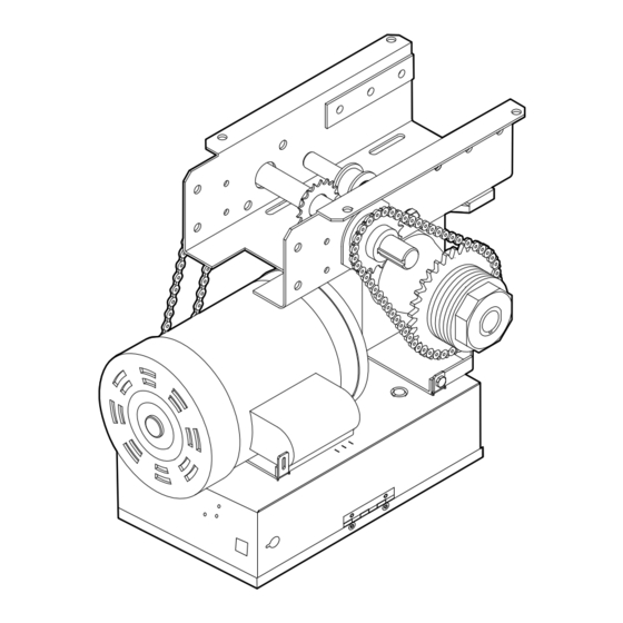
ALL of which are under EXTREME tension and can cause SERIOUS PERSONAL On models J, H, HJ and GH operators the drive sprocket can be INJURY. mounted on either the right or left side. -
Page 17: Mounting
MOUNTING Place the door sprocket on the door shaft. Place the operator drive sprocket on the appropriate side of the operator for your installation type. Wrap the drive chain around the door sprocket and the drive sprocket then secure with the master link. Align the door and the drive sprockets. -
Page 18: Wiring
WIRING WARNING WARNING To reduce the risk of SEVERE INJURY or DEATH: • ALL electrical connections MUST be made by a qualified individual. • ANY maintenance to the operator or in the area near the operator MUST NOT be performed until disconnecting the •... -
Page 19: Control Station
NING WARNING CONTROL STATION WARNING WARNING To prevent possible SERIOUS INJURY or DEATH from • Install the entrapment warning placard on wall next to the electrocution: control station in a prominent location that is visible from the door. • Be sure power is NOT connected BEFORE installing door control. -
Page 20: Entrapment Protection
MONITORED ENTRAPMENT PROTECTION DEVICES • Be sure power is NOT connected to the door operator BEFORE A LiftMaster Monitored Entrapment Protection (LMEP) device is installing the photoelectric sensor. required for most wiring types (refer to page 29). The operator •... -
Page 21: Install The Photoelectric Sensors (Provided)
INSTALL THE PHOTOELECTRIC SENSORS (PROVIDED) The following instructions show recommended assembly of the bracket(s) and “C” wrap based on the wall installation of the photoelectric sensors on each side of the door or on the door tracks themselves. There are also alternate mounting methods which may fi t your installation requirements better. -
Page 22: Mount The Photoelectric Sensors (Provided)
Invisible Light Beam Protection Area Photoelectric Sensor 6" (15 cm) max. above fl oor WIRE THE LIFTMASTER MONITORED ENTRAPMENT PROTECTION (LMEP) DEVICES Connect the LiftMaster Monitored Entrapment Protection (LMEP) device to the logic board according to the models shown below:... -
Page 23: Adjustment
WARNING ADJUSTMENT IMPORTANT SAFETY INSTRUCTIONS WARNING WARNING TO REDUCE THE RISK OF SEVERE INJURY OR DEATH: 1. READ AND FOLLOW ALL WARNINGS AND INSTRUCTIONS. 8. After ANY adjustments are made, the entrapment protection device MUST be tested. Failure to adjust the operator 2. -
Page 24: Clutch Adjustment (Belt Drive Model Operators)
By removing the centrifugal switch on single phase motors, the leading cause of motor failures is eliminated. (Auxiliary Reversal System not applicable on models GH and GT.) Logic Board NOTE: This feature is automatically learned and does not require programming. -
Page 25: Testing
WARNING WARNING TESTING Apply power to the operator. CAUTION WARNING WARNING When power is applied to the operator, the following LED’s will illuminate: STOP, CLOSE, OPEN, LMEP, 24Vac, RADIO, DATA, To avoid SERIOUS personal INJURY or DEATH: TIMER ENABLE, OLS MID, SLS, CLS, and MAS. Once the power •... -
Page 26: Manual Release
MANUAL RELEASE EMERGENCY DISCONNECT SYSTEM WARNING WARNING MODEL GT AND T To prevent possible SERIOUS INJURY or DEATH from a falling TO DISCONNECT DOOR FROM OPERATOR door or arm: CAUTION The door should be in the fully closed position if possible. •... -
Page 27: Emergency Disconnect System Model H, Gh, J, And Hj
WARNING EMERGENCY DISCONNECT SYSTEM CAUTION CAUTION MODEL H, GH, J, AND HJ To prevent possible SERIOUS INJURY from a moving chain: • DISCONNECT electric power to the operator BEFORE manually This operator has provisions for manually operating the door operating your door. -
Page 28: Programming
PROGRAMMING INTRODUCTION TO PROGRAMMING Many programmable functions require that a LiftMaster Entrapment Protection (LMEP) device be installed in order to function. Refer to the Entrapment Protection section. LOGIC BOARD OVERVIEW DATA Optional Auxiliary Card Receptacles 24VAC Single Phase & POWER... -
Page 29: Determine And Set Wiring Type
LIFTMASTER MONITORED ENTRAPMENT PROTECTION (LMEP) LIFTMASTER MONITORED ENTRAPMENT PROTECTION (LMEP) DEVICE IS REQUIRED DEVICE IS RECOMMENDED A LiftMaster Entrapment Protection (LMEP) device is required for A LiftMaster Entrapment Protection (LMEP) device is the following wiring types. recommended for the following wiring types. -
Page 30: Programming Remote Controls
To prevent possible SEVERE INJURY or DEATH: CAUTION • Activate door ONLY when it can be seen clearly, is properly • Install a LiftMaster Monitored Entrapment Protection (LMEP) adjusted and there are no obstructions to door travel. device. • ALWAYS keep door in sight until completely closed. NEVER •... -
Page 31: Programming Remote Controls
PROGRAMMING REMOTE CONTROLS NOTE: The following programming requires a LiftMaster REMOTE CONTROL PROGRAMMING FEATURE Monitored Entrapment Protection (LMEP) device. Program Remote Controls from the 3-button control station Your 315 MHz Security✚ ® or dip switch remote control can be (3BCS). -
Page 32: Maintenance Alert System (Mas)
MAINTENANCE ALERT SYSTEM (MAS) Feature: An internal cycle counter will activate a flashing LED on the 3-button control station when the preset number of cycles or SELECTOR DIAL months has elapsed (whichever occurs first). Setting this feature is optional. By default this feature will never activate. Logic 4 operators incorporate a self diagnostic feature built into the MAS LED. -
Page 33: Open Mid Stop
To prevent possible SEVERE INJURY or DEATH: • Activate door ONLY when it can be seen clearly, is properly CAUTION • Install a LiftMaster Monitored Entrapment Protection (LMEP) adjusted and there are no obstructions to door travel. device. • ALWAYS keep door in sight until completely closed. NEVER •... -
Page 34: Car Dealer Mode
FSTS must first connect a treadle, photoelectric sensor or loop detector DIAG accessory to the SBC input and must have at least one LiftMaster Monitored Entrapment Protection (LMEP) device installed (refer to OPTN page 20). Wiring type must be set to TS or T. -
Page 35: Maximum Run Timer (Mrt)
The remote controls will still be learned PROG g. Remote control programming via the 3-button station h. The LiftMaster Monitored Entrapment Protection (LMEP) device will be unprogrammed NOTE: Life of Operator feature (Odometer/Cycle Counter) and programmed remote controls are not cleared. -
Page 36: Maintenance
Fasteners Check and tighten as required. Manual Disconnect Check and operate. Bearings and Shafts Check for wear and lubricate. LiftMaster Monitored Check alignment and Entrapment Protection functionality. (LMEP) HOW TO ORDER REPAIR PARTS Use SAE 30 Oil (Never use grease or silicone spray). -
Page 37: Troubleshooting
TROUBLESHOOTING DIAGNOSTIC CHART The logic board has several LEDs to assist in the installation and troubleshooting of the operator. The following chart should assist in verifying the operator is functioning properly. Turn the selector dial to DIAGNOSTIC to keep the door from moving while troubleshooting. -
Page 38: Troubleshooting Guide
TROUBLESHOOTING GUIDE FAULT POSSIBLE CAUSE THE OPERATOR WILL a) No power supply Verify primary line voltage from power source. Green POWER LED ➤ NOT RESPOND TO ANY must be on. COMMANDS b) Operator control station is wired wrong ➤ Use the OPEN, CLOSE and STOP LEDs to help check correct wiring. Verify that the board is accepting commands by using the onboard station. -
Page 39: Troubleshooting Error Codes
Option card will not function Refer to accessories page for list option card receptacles properly of supported option card(s). 7 blinks LiftMaster Monitored Entrapment Normal operation (5 second Cleared when safety device is Protection (LMEP) device faulted constant pressure override cleared or connected. -
Page 40: Troubleshooting Radio Functionality
LMEP LED flashes Cannot close via constant pressure in No safety device present - Must connect a LiftMaster C2, D1 or E2 modes. A safety device is required to Monitored Entrapment close via constant pressure. -
Page 41: Wiring Diagrams
230V MOTOR CONNECTION Close Sensing NOTE: Gray (GY) and purple (PU) motor wires are reversed Edge for H and HJ right hand models and all GH and J models. Stop Refer to page 26 for LiftMaster Monitored Entrapment Protection (LMEP) -
Page 42: Logic (Ver. 4.0) 3 Phase Wiring Diagram
575V MOTOR CONNECTION Open NOTE: Gray (GY) and purple (PU) motor wires are reversed for H and HJ right hand 3-Button Station Close models and all GH and J models. Sensing Edge Stop Refer to page 26 for LiftMaster Monitored... -
Page 43: Accessories
The Auxiliary Contact option card has both Normally-Open H, DJ, and DH operators. May be welded. and Normally-Closed contacts that actuate when the door is Cast iron bracket to mount J, H, DH, DJ, and GH side mount idle, opening, or closing. 08-9098 operators on end bracket of a rolling door or grill. -
Page 44: Control Connection Diagram
B2, T, TS & FSTS MODE ONLY Any Commercial Type Keyswitch See note 2. LiftMaster Brand Receiver SENSING DEVICE TO REVERSE OR STOP EXTERNAL INTERLOCK Note: 11 and 4 are both the same common. Remove Factory Installed Jumper Either is acceptable.