
Related Manuals for Omron CS1W-PRM21


Summary of Contents for Omron CS1W-PRM21
- Page 1 SYSMAC CS/CJ-series CS1W-PRM21 CJ1W-PRM21 PROFIBUS-DP Master Units Operation Manual (Draft) Produced November 17, 2003...
- Page 3 OMRON Product References All OMRON products are capitalized in this manual. The first letter of the word Unit is also capitalized when it refers to an OMRON product, regardless of whether it appears in the proper name of the prod- uct.
- Page 4 OMRON. No patent liability is assumed with respect to the use of the information contained herein. Moreover, because OMRON is con- stantly striving to improve its high-quality products, the information contained in this manual is subject to change without notice.
-
Page 5: Table Of Contents
TABLE OF CONTENTS About this Manual ....... . . PRECAUTIONS ........Intended Audience . - Page 6 TABLE OF CONTENTS Command / Response Reference ..........SECTION 6 Operation .
-
Page 7: About This Manual
About this Manual This manual describes the CS1W-PRM21 and CJ1W-PRM21 PROFIBUS-DP Master Units. It also describes how to install and operate them. Both Units serve the same purpose: enable devices of var- ious manufacturers to intercommunicate without making any special interface adaptations. They are technically the same;... - Page 8 Manual Products Contents Cat. No. C200H-series PROFIBUS-DP SYSMAC C200H-series Describes the Installation and Opera- W349-E2-@ Master Units C200HW-PRM21 tion of the C200HW-PRM21 PROFI- Operation Manual BUS-DP Master Units. CJ-series PROFIBUS-DP SYSMAC CJ1-series Describes the Installation and Opera- W408-E2-@ Slave unit CJ1W-PRT21 tion of the CJ1W-PRT21 PROFIBUS- Operation Manual...
-
Page 9: Precautions
PRECAUTIONS This section provides general precautions for using the PROFIBUS-DP Master Units, Programmable Controllers and related devices. The information contained in this section is important for the safe and reliable operation of the PROFIBUS-DP Master Units. You must read this section and understand the information contained before attempting to set up or operate a PROFIBUS-DP Master Unit and PLC system. -
Page 10: Intended Audience
It is extremely important that all PLC Units be used for their specified pur- poses and under the specified conditions, especially in applications that can directly or indirectly affect human life. You must consult your OMRON repre- sentative before using a PLC System in the above-mentioned applications. -
Page 11: Operating Environment Precautions
Operating Environment Precautions !WARNING Execute online edits only after confirming that no adverse effects will be caused by extending the cycle time. Otherwise, the input signals may not be readable. Operating Environment Precautions !Caution Do not operate the Unit in the following places: •... - Page 12 Application Precautions • Install double safety mechanisms to ensure safety against incorrect sig- nals that may be produced by broken signal lines or momentary power interruptions. • When adding a new station to the network, make sure that the baud rate is the same as other nodes.
-
Page 13: Conformance To Ec Directives
EMC-related performance of OMRON Units complying with EC Directives will vary depending on the configuration, wiring, and other conditions of the equip- ment or control panel in which OMRON devices are installed. The customer must, therefore, perform final checks to confirm that units and the overall sys- tem conforms to EMC standards. -
Page 14: Conformance To Ec Directives
Conformance to EC Directives Units that meet EC directives also meet the common emission standard (EN50081-2). The measures necessary to ensure that the standard is met will vary with the overall configuration. You must therefore confirm that EC direc- tives are met for the overall configuration, particularly any radiated emission requirement (10 m). -
Page 15: Features And Specifications
SECTION 1 Features and Specifications This section provides an introductory overview of PROFIBUS, its functions and how to setup and configure a network. It also addresses the PROFIBUS-DP Master Units and the Configurator, their features and specifications. Overview of PROFIBUS ......... 1-1-1 Introduction. -
Page 16: Overview Of Profibus
Overview of PROFIBUS Section 1-1 Overview of PROFIBUS 1-1-1 Introduction Standard EN50170r PROFIBUS (PROcess FIeldBUS) is an open fieldbus standard for a wide range of applications in manufacturing, processing and building automation. The Standard, EN 50170 (the Euronorm for field communications), to which PROFIBUS adheres, guarantees vendor independence and transparency of operation. - Page 17 Overview of PROFIBUS Section 1-1 • Layer 7, the Application Layer of this model, defines the application func- tions. This Layer is only applicable to PROFIBUS-FMS. DP-Profiles DP-Extensions User Interface Layer DP Basic Functions (7) Application Layer (6) Presentation Layer (5) Session Layer NOT DEFINED (4) Transport Layer...
-
Page 18: Device Types
PROFIBUS-DP class 2 Master (DPM2) devices are programmers, configura- tion devices or operator panels. They are used during commissioning, for con- figuration of the DP system, or for operation and monitoring purposes. The CS1W-PRM21 and the CJ1W-PRM21 are both PROFIBUS-DP Class 1 Master devices. Slave devices Slave devices are peripheral devices. -
Page 19: Diagnostic Functions
Overview of PROFIBUS Section 1-1 Token Passing DPM1 DPM2 DPM 1 Active stations Master devices Polling PROFIBUS Passive stations Slave devices The three masters form a logical token ring. When an active station receives the token message, it can perform its master role for a certain period of time. During this time it can communicate with all assigned slave stations in a mas- ter-slave communication relationship, and a DPM2 master can take the initia- tive to communicate with DPM1 master stations in a master-master... -
Page 20: Protection Mechanisms
Overview of PROFIBUS Section 1-1 1-1-6 Protection Mechanisms Monitoring Time PROFIBUS-DP provides effective protection functions against parameteriza- tion errors or failure of the transmission equipment. Time monitoring is pro- vided both at the master and the slave devices. The monitoring interval is specified when the system is configured. -
Page 21: Setting Up A Profibus-Dp Network
Setting up a PROFIBUS-DP Network Section 1-2 Setting up a PROFIBUS-DP Network 1-2-1 Configuring the PROFIBUS-DP Master In order to operate a PROFIBUS network, each master in the network needs to be configured. This process of PROFIBUS master configuration involves •... -
Page 22: Gsd File Technology
CX-Profibus is a FDT container application. Together with this container appli- cation, OMRON provides two DTMs: • A DTM to facilitate configuration of the CS1W-PRM21/CJ1W-PRM21 PROFIBUS Master Units • A DTM to facilitate integration of GSD file based devices in to CX-Profibus... -
Page 23: Profibus-Dp Master Unit
The PROFIBUS-DP Master Unit is a CPU Bus Unit, which can be installed on a CS1/CJ1 PLC System. There are two available models of the PROFIBUS- DP Master unit: the CS1W-PRM21 for connection to a CS1 PLC System and the CJ1W-PRM21 for connection to a CJ1 PLC System. Both models provide identical functionality. -
Page 24: Specifications
Types of communications Model number CS Series CPU Bus Unit • Remote I/O communications master CS1W-PRM21 CJ Series CJ1W-PRM21 General Specifications General specifications of the CS/CJ-series PROFIBUS-DP Master Units con- form to the general specifications for the SYSMAC CS/CJ-series CPU Units. - Page 25 PROFIBUS-DP Master Unit Section 1-3 Functional Specifications Item Specification PROFIBUS-DP Master Unit types CS1W-PRM21 CJ1W-PRM21 Applicable PLC series CS-series CJ-series Mounting position • CPU Rack, • CPU Rack, • CJ1 Expansion Rack • CS Expansion Rack (Not in- cluding a C200H Expansion I/O Rack or SYSMAC BUS Slave Rack.)
- Page 26 PROFIBUS-DP Master Unit Section 1-3 Item Specification Reading Slave station diagnostics The MEMORY AREA READ (0101) FINS command can be used to obtain the last received Slave Diagnostics message. Reading and controlling the error log The internal error log records the history of error events. The Unit supports the following Error Log related FINS commands: •...
- Page 27 Number of diagnostics data supported by Up to 244 bytes of diagnostics max. per Slave station Master Diagnostic data is collected at the Unit, and can be obtained from the Unit using FINS messaging External Dimensions CS1W-PRM21 PRM21 COMM COMM ISOM ISOM...
-
Page 28: Comparison With Previous Model
PROFIBUS-DP Master Unit Section 1-3 1-3-3 Comparison with Previous Model The following table provides a comparison between the CS1W-PRM21/ CJ1W-PRM21 PROFIBUS-DP Master Units and their predecessor, the C200HW-PRM21 PROFIBUS-DP Master used in a CS-series PLC Item C200HW-PRM21 CS1W-PRM21/CJ1W-PRM21 Unit classification... - Page 29 PROFIBUS-DP Master Unit Section 1-3 Item C200HW-PRM21 CS1W-PRM21/CJ1W-PRM21 PROFIBUS Connector 9-pin sub-D female connector (#4/40 UNC 9-pin sub-D female connector (#4/40 UNC thread) thread) Termination provided through a switch on Termination must be provided by the cable the unit according to EN50170...
-
Page 30: Cx-Profibus Configurator
CX-Profibus The PROFIBUS-DP Master Unit requires a configuration before it can exchange I/O data with the Slave stations. For this purpose OMRON provides the CX-Profibus Configuration program, which runs under Microsoft Win- dows™ NT 4.0, Windows™ 2000 or Windows™ XP... - Page 31 • CS1W-PRM21/CJ1W-PRM21: Connection to the Unit is achieved through the serial port of the PLC CPU, using CX-Server. Cox-Server also allows routing the download through multiple systems, if supported by these systems. The CS1W-PRM21/CJ1W-PRM21 Units do not sup- port message routing. Serial connection to CS/CJ-series...
-
Page 32: Specifications
• Serial port: RS-232C; COM1 to COM4 supported Operating System • MS Windows NT4.0 • MS Windows 2000 • MS WindowsXP Connection to CS1W-PRM21/CJ1W- • Peripheral or RS-232C port of PC with PLC CPU. Serial commu- PRM21 nications mode: Peripheral bus, Host Link, Toolbus, supported by CX-Server. - Page 33 CX-Profibus Configurator Section 1-4 Item Specification Device setup Device setup allows the user to: • Set the Unit number related to the actual PROFIBUS-DP Master unit. • Configure the communication link between the PC and the Unit. This function invokes the User Interface of CX-Server. •...
-
Page 34: Basic Operating Procedure
Basic Operating Procedure Section 1-5 Basic Operating Procedure 1-5-1 Overview The following diagram provides an overview of the installation procedures. For experienced installation engineers, this may provide sufficient informa- tion. For others, cross-references are made to various sections of this manual where more explicit information is given. -
Page 35: Preparations For Communications
Basic Operating Procedure Section 1-5 1-5-2 Preparations for Communications 1,2,3... 1. Mount the Master Unit on the PLC system (refer to 2-2 Installing the PROFIBUS-DP Master Unit ). • Treat the Unit as a CPU Bus Unit. • It can be mounted to a CPU Rack or Expansion Rack. •... - Page 36 Basic Operating Procedure Section 1-5...
-
Page 37: Installation And Wiring
Handling Precautions ........2-2-2 Mounting the CS1W-PRM21 ......2-2-3 Mounting the CJ1W-PRM21 . -
Page 38: Unit Components
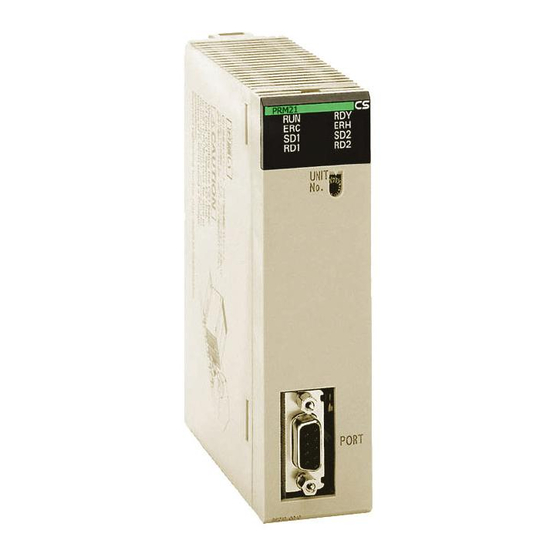
The illustration below shows the Status LED indicators, the Unit number selector switch, and a 9-pin female sub-D connector on the front side of the CS1W-PRM21 and the CJ1W-PRM21 Units. Each of these components are explained in the following sections... -
Page 39: Indicators
Unit Components Section 2-1 2-1-2 Indicators The PROFIBUS-DP Master Units are each fitted with seven LEDs to indicate the operational mode and status of the Unit and the PROFIBUS network CS1W-PRM21 CJ1W-PRM21 PRM21 COMM PRM21 COMM COMM Indicator specifications Indicator... -
Page 40: Switch Settings
CPU Bus Unit is mounted to the same PLC. The unit number must be unique for each CPU Bus Unit. Selecting a non-unique number for a CPU Bus Unit will prevent the PLC System from starting correctly. CS1W-PRM21 CJ1W-PRM21 Setting range:... -
Page 41: Profibus Connector
Unit Components Section 2-1 DM Area Allocations Unit No. Allocated words Unit No. Allocated words (decimal) (decimal) 0 (0) D30000 to D30099 8 (8) D30800 to D30899 1 (1) D30100 to D30199 9 (9) D30900 to D30999 2 (2) D30200 to D30299 A (10) D31000 to D31099 3 (3) -
Page 42: Installing The Profibus-Dp Master Unit
2-2-2 Mounting the CS1W-PRM21 The CS1W-PRM21 PROFIBUS-DP Master Unit can be mounted to any slot in either a CS-series CPU Rack, a CS-series Expansion CPU Rack or a CS1 Duplex CPU Rack. The CS-series PLC supports up to 7 Expansion CPU Racks, in addition to the CPU rack. - Page 43 Installing the PROFIBUS-DP Master Unit Section 2-2 Mounting Procedure Mount the CS1W-PRM21 PROFIBUS-DP Master Unit to the Backplane using the following procedure. !Caution Always turn OFF the power supply to the PC before mounting or dismounting a Unit or connecting or disconnecting cables.
-
Page 44: Mounting The Cj1W-Prm21
Installing the PROFIBUS-DP Master Unit Section 2-2 2-2-3 Mounting the CJ1W-PRM21 The PROFIBUS-DP Master Unit can be mounted to any slot in either a CJ- series CPU Rack, or a CJ-series Expansion CPU Rack. The CJ-series PLC supports up to 4 Expansion CPU Racks, in addition to the CPU rack. The number of slots to which PROFIBUS-DP Master Unit can be mounted in any of the positions shown below using the sliders on the top and bottom of the Unit. -
Page 45: Initial Setup Procedure
Initial Setup Procedure Section 2-3 Mounting Procedure Mount the CJ1W-PRM21 PROFIBUS-DP Master Unit to the PLC using the fol- lowing procedure. 1. Carefully align the connectors to mount the PROFIBUS-DP Master Unit. Connector PA20 5R POWE R SYSMA C CJ1G-C PU44 ERR/ALM COMM PROGRAMM ABLE... -
Page 46: Selecting A Unit Number
Initial Setup Procedure Section 2-3 2-3-1 Selecting a unit number 1. Make sure that the PLC Power Supply is turned OFF before setting the Unit number. 2. Set the switch to the desired unit number. Use a small screwdriver to make the setting, taking care not to damage the rotary switch. -
Page 47: Setting Up A Network
Setting up a Network Section 2-4 Initial screen SHIFT 000000 I/O TBL ? 000000 I/O TBL WRIT ???? WRITE Password 000000CPU BU ST? 0:CLR 1:KEEP (Save or clear the CPU Bus Unit System Setup.) 000000 I/O TBL WRIT OK After creating the I/O table, the Unit is ready to be configured for first use on the PROFIBUS-DP network. - Page 48 4 segments. The maximum number of PROFIBUS stations in such a network is then 122. The figure below shows an example of a two-segment network. OMRON SYSMAC CS1G P R O G R A MMA B LE...
- Page 49 Setting up a Network Section 2-4 Cable Type The PROFIBUS standard EN 50170 specifies Type A shielded, twisted- pair cable as the recommended cable type for use in an RS-485 based PROFI- BUS network. This cable type has the following characteristics: Characteristic Value Impedance...
-
Page 50: Bus Termination
Setting up a Network Section 2-4 2-4-2 Bus Termination Termination resistors In order to minimize cable reflections and ensure a defined signal level on the data lines, the data transfer cable must be terminated at both ends with a ter- minating resistor combination. -
Page 51: Defining Profibus-Dp In The Software
Defining the Configuration After making the physical connections of the network, the configuration then has to be defined in the software. OMRON provides a dedicated PC-based configuration program, called CX-Profibus, as well as the required DTMs for this purpose. It must be used to: •... - Page 52 Defining PROFIBUS-DP in the Software Section 2-5...
-
Page 53: Configuration Software
SECTION 3 Configuration Software This section contains the procedures for installing the configuration software. It also presents an overview of the Configuration software and discusses the main aspects of defining a PROFIBUS configuration. Installation........... . 3-1-1 Installation Requirements . -
Page 54: Installation
• CX-Server, to allow communication between the PC and the PLC • Generic Slave Device DTM, to allow slave configuration using GSD files. • Additional GSD files for several OMRON slave stations. Note 1. Provided with the CD-ROM is a 16-digit installation key, which can be found on a label attached to the CD-ROM box. - Page 55 Installation Section 3-1 5. The operations and displays shown in the following procedure may differ slightly depending on the version of Windows software being used. The displays for Windows 2000 are shown here. 1,2,3... 1. Exit all other Windows-based programs. 2.
- Page 56 Installation Section 3-1 5. After starting the Microsoft.NET framework installation process, a window will be displayed showing the progress of this installation. 6. Completion of the Microsoft.NET framework installation is indicated by dis- playing the message window below. 7. After installing the Microsoft.NET framework, CX-Profibus and its compo- nents will be installed.
- Page 57 Installation Section 3-1 cense. If the License is not accepted - by selecting the No button -, the in- stallation will be terminated. 9. After accepting the License statement, the window below is displayed to al- low you to enter your name, your Company name and the 16-digit License key provided on the back side of the CD-ROM case.
- Page 58 Installation Section 3-1 mation is correct, select the Yes button. Selecting the No button will revert you to the previous window. 11. After entering the correct License code, the installation process will first re- quire you to select the language to be installed for CX-Profibus and its components.
- Page 59 Section 3-1 13. Specify a Program Folder to which a shortcut to the program will be added. The default Program Folder is OMRON\CX-Profibus. You can specify any one of the other available Program Folders listed in the Existing Folders frame. After making the desired selection, select the Next button. The in- stallation will now be performed, the files will be copied to the destination folder and the necessary registry entries will be made...
- Page 60 17. Click the Finish Button to finalize installation and exit the setup program. This completes installation of the CX-Profibus. 18. In order to be ensured of OMRON support for the program as well as in- formation on updates, please fill out the registration card supplied with the software package and return it to the OMRON regional sales office or to your local OMRON representative.
-
Page 61: Cx-Profibus
3-2-1 Starting CX-Profibus Starting CX-Profibus Select Program, OMRON, and CX-Profibus, from the Start Menu if the default program folder name is used. At startup, the CX-Profibus splash screen will appear, on top of which a login window as shown below will be displayed. -
Page 62: Cx-Profibus Main Window
CX-Profibus Section 3-2 3-2-2 CX-Profibus Main Window The main application window of CX-Profibus will open with a New Project. After the first start up, the Device Catalogue will be opened automatically. If not, the Device Catalogue may be opened from the menu. The figure below shows the opened CX-Profibus application window with a Project already containing a network, and the Device Catalogue window opened. - Page 63 CX-Profibus Section 3-2 The highest level of the tree is the project. The next level is the PROFIBUS Master level. On this level one or more PROFIBUS-DP Master devices can be allocated. The third level contains the slave DTMs. The PROFIBUS network must be assembled in the Network Window, i.e. the various DTMs are added to the network via this window.
- Page 64 CX-Profibus Section 3-2 Menu Command Short Key Description View Network View Hides or un-hides the Network View window. Device Catalogue Opens or closes the Device Catalogue. Tool Bar Hides or un-hides the Tool Bar. Status Bar Hides or un-hides the Status Bar. Error Logging Hides or un-hides the Error Logging window.
-
Page 65: Device Catalogue
CX-Profibus Section 3-2 3-2-3 Device Catalogue Device Catalogue main The Device Catalogue is one of the main components in CX-Profibus. Its components main functions are • to maintain a list of installed DTM and GSD files. • to provide convenient sorting and categorizing of the list. •... - Page 66 CX-Profibus Section 3-2 Column Description Device The Device column contains the names of the DTMs, as provided by the DTM or the GSD file. If the device is defined by a GSD file, the Generic Slave Device DTM reads out the GSD file entry “Model Name”.
-
Page 67: Updating The Device Catalogue
CX-Profibus Section 3-2 window with additional DTM information. The figure below provides an exam- ple for the CJ1W-PRM21 PROFIBUS-DP Master DTM. 3-2-4 Updating the Device Catalogue If a new DTM has been installed, it will not automatically be included in the Device catalogue. -
Page 68: Adding Devices To The Network
CX-Profibus Section 3-2 Saving the data is initiated from CX-Profibus, but every DTM must support the save function as well. The settings of each DTM are added to the Project file by the DTM itself. A Project file can be opened using the File - Open menu option. This will open the standard Windows File selection window, after which the Project file can be selected and opened. -
Page 69: Exporting To Html
CX-Profibus Section 3-2 Using Drag & Drop 1,2,3... 1. Open the Device Catalogue: Either select the View - Device Catalogue menu option, or press the button in the Tool Bar. 2. Select a device DTM in the Device Catalogue. 3. Left click the mouse and Drag the mouse pointer to the desired location in the network. -
Page 70: Error Logging And Fdt Monitoring
CX-Profibus Section 3-2 Exporting DTM Exporting single DTM information to HTML is achieved by the following information to HTML sequence. 1,2,3... 1. Select the DTM in the network window. 2. Right click the mouse to bring up the context menu. 3. -
Page 71: Access Control And User Management
CX-Profibus Section 3-2 cation is listed as a sequence of function calls from the CX-Profibus to a DTM and vice versa. Note The FDT Monitoring window is hidden by default. After starting CX-Profibus, the window will be displayed, by selecting the View - FDT Monitoring option from the main menu. - Page 72 CX-Profibus Section 3-2 Function Observer Operator Maintenance Planning Administrator Engineer New file Allowed Allowed Allowed Allowed Allowed Open file Allowed Allowed Allowed Allowed Allowed Save File Not allowed Not allowed Not Allowed Allowed Allowed Save As... Not allowed Not allowed Allowed Allowed Properties...
- Page 73 CX-Profibus Section 3-2 access levels do not have access to this menu option. The selection opens the User Accounts window, as shown below. Changing access rights By selecting the check box next to a level, the Administrator can grant access rights to CX-Profibus, i.e.
-
Page 74: Profibus-Dp Master Dtm
To allow configuration and data monitoring from within CX-Profibus a CS1/ CJ1 PROFIBUS-DP Master DTM is installed, together with CX-Profibus. The DTM shows up in the Device Catalogue under two different names. • CS1W-PRM21 PROFIBUS Master • CJ1W-PRM21 PROFIBUS Master The PROFIBUS-DP Master DTM has two main user Interface components. - Page 75 PROFIBUS-DP Master DTM Section 3-3 Master DTM Configuration The Master DTM Configuration User Interface consist of four tabbed win- User Interface dows: • Device Setup tab • Master Setup tab • Bus Parameter tab • Slave Area tab The four tabbed windows are discussed below. Configuration Interface The Master DTM Configuration User Interface contains four general buttons.
- Page 76 The Configure button invokes the CX-Server communications settings dia- log. CX-Server is the driver software, providing the communication functional- ity between a PC and the PLC CPU. It is the basis for the OMRON’s CX-Suite programs. CX-Server is provided with CX-Profibus, but it may already be installed on the PC, if other programs, for example CX-Programmer have been installed.
- Page 77 PROFIBUS-DP Master DTM Section 3-3 Master Setup Tab The Master Setup tab contains settings regarding the behavior of the PROFI- BUS-DP Master Unit itself. The Master Setup tab is shown below. Action to PLC Mode The Action to PLC Mode Transition Box defines the behavior of the Unit on Transition Box the PROFIBUS network, in case a PLC mode change occurs.
- Page 78 PROFIBUS-DP Master DTM Section 3-3 Control Description Auto-CLEAR Mode ON Selected Unit transitions to the CLEAR mode in the event of a network error, e.g. because one or more configured slaves are not in the Data Exchange mode. Auto-CLEAR Mode OFF Selected Unit does not transition to CLEAR mode, but attempts to re-parameterize the slave station.
- Page 79 PROFIBUS-DP Master DTM Section 3-3 The table below lists the Bus Parameters, which are shown in the Bus Param- eter tab. Item Description Unit Editable by User Baud rate Defines the transmission rate on the PROFIBUS-DP Network. The following baud rate values are defined by the PROFIBUS-DP standard: •...
- Page 80 PROFIBUS-DP Master DTM Section 3-3 Item Description Unit Editable by User GAP Update The GAP update factor defines the amount of updates of the active stations (i.e. Factor Master stations) list times during one token rotation cycle. To update the list, the Master station will transmit FDL_Status_request messages to ascending station addresses until it finds a next Master station, or until it reaches the Highest Station Address (See HSA below).
- Page 81 PROFIBUS-DP Master DTM Section 3-3 Collective List Box The collective list contains the following information (refer to figure above, the table applies to the lists in both Allocation tabs). Column Description #Addr. Station address on the network, obtained from the slave DTM. Index Index number of the I/O module.
-
Page 82: Diagnostics User Interface
PROFIBUS-DP Master DTM Section 3-3 Note 1. If the selected PLC memory area, on to which the data must be mapped is not supported by the PLC CPU, a warning message will be displayed upon downloading the configuration. 2. If an invalid setting is made the calculated length value will change its color to red, indicating an invalid setting. - Page 83 PROFIBUS-DP Master DTM Section 3-3 In order to access the Diagnostics User Interface, the DTM has to be on-line, i.e. a communication channel between the DTM and the PROFIBUS-DP Mas- ter Unit must have been established. Opening the DTM In order to open the DTM Diagnostics User Interface perform the following Diagnostics User Interface sequence.
- Page 84 PROFIBUS-DP Master DTM Section 3-3 • Master Status tab. • Slave Status tab. • Error History tab. Also in the Monitor tab, the method of Diagnostics data refreshing can be selected. • Automatic The Diagnostics data is constantly retrieved from the Unit. •...
- Page 85 PROFIBUS-DP Master DTM Section 3-3 LED Indicator Description Unit Error A Unit error indicates that a new error has been set in the Unit Status word (see section 4-2-3 Unit Status (Word n+4) ). Master Error A Master Error indicates that a new error has been set in the Master Status 2 word (see section 4-2-5 Master Status 2 (Word n+6) ).
- Page 86 PROFIBUS-DP Master DTM Section 3-3 Indicator Color Slave Status Grey Slave not allocated or station is another master station. The slave station is not communicating with the PROFI- BUS-DP Master Unit. It may be disconnected, or the Master is in OFFLINE or STOP mode. Orange The slave station is communicating with the PROFI- BUS-DP Master Unit, but it is not in Data Exchange.
- Page 87 PROFIBUS-DP Master DTM Section 3-3 The Error Log entries are described in section 7-5-2 Error Codes . Refer to this section for details. Clear Button Pressing the Clear Button, initiates an ERROR LOG CLEAR FINS command. All error messages in the Unit and the displayed list will be cleared. Online Operations The Online Operations tab is the second main tab in the DTM Diagnostics User Interface.
-
Page 88: Connecting To The Profibus-Dp Master Unit
PROFIBUS-DP Master DTM Section 3-3 Global_Control Messages Global_Control messages can be initiated by the user from the Online Opera- tions tab. The user can select the Global_Control commands. • Freeze. • Unfreeze. • Sync. • UnSync. All commands can be transmitted independent from each other, i.e. all can be send at the same time. - Page 89 PROFIBUS-DP Master DTM Section 3-3 Configuring CX-Server In order to configure CX-Server for communication with the Unit, perform the following procedure. 1,2,3... 1. Select the type of PLC to which the Unit is attached, from the Device Type drop down selection box. 2.
- Page 90 PROFIBUS-DP Master DTM Section 3-3 5. Make the necessary selections to facilitate communication between the PC and the PLC CPU to which the PROFIBUS-DP Master Unit is attached, and press the OK button. Testing CX-Server setup After making the settings, press the OK button to close the CX-Server inter- face.
-
Page 91: Generic Slave Device Dtm
Most of the current PROFIBUS-DP slave devices are supplied with a GSD file in order to allow a configurator to setup a configuration for that particular slave device. OMRON’s Generic Slave Device DTM is provided to allow integration of the GSD file based configuration options in to an FDT Container applica- tion, like CX-Profibus. - Page 92 Generic Slave Device DTM Section 3-4 The Configuration User Interface for the Generic Slave Device DTM, contains three tabbed windows. Above these windows the Device, the Manufacturer, the GSD file and the Unit’s PROFIBUS ID number are displayed. Configuration Tab The Configuration tab contains the Device settings and the I/O Module Con- figuration.
- Page 93 The Parameter tab lists all settings to be made for the Parameter message. The Parameter tab is shown below (Example shown is the Parameter tab for an OMRON CJ1W-PRT21 PROFIBUS-DP Slave Unit). Common Parameters The PROFIBUS-DP parameter message contains a number of settings for the slave device.
-
Page 94: Diagnostics User Interface
Generic Slave Device DTM Section 3-4 Selecting the Groups The User can check the check boxes for each group the slave device will belong to. The group setting is transferred to the slave device as part of the parameter message. 3-4-2 Diagnostics User Interface The Generic Slave Device DTM provides a Diagnostics User Interface to dis-... - Page 95 Generic Slave Device DTM Section 3-4 retrieving it from the PROFIBUS-DP Master Unit. A Green LED indicator in the lower left corner will indicate whether or not the device is on-line. Diagnostics Tab The Diagnostics tab displays basic diagnostics for the slave. An example of the Diagnostic tab is shown below.
- Page 96 Generic Slave Device DTM Section 3-4 Name Description Static diagnostics When set, the slave station reports static diagnostics, i.e. the error event is serious enough that the diagnostics is continuously reported. No data exchange will be performed. Re-parameterization When set, the slave indicates that it requires a new parameter setting. The slave station is requested not in Data_Exchange with the Master Unit.
-
Page 97: Allocated Cio And Dm Words
SECTION 4 Allocated CIO and DM Words This section describes the words allocated to PROFIBUS-DP in the CIO and DM Areas. These words facilitate controlling the PROFIBUS-DP Unit and accessing the Unit and network statuses. Overview of Word Allocations ........4-1-1 CIO Area Word Allocations . -
Page 98: Overview Of Word Allocations
Overview of Word Allocations Section 4-1 Overview of Word Allocations The words shown in the following diagram are allocated according to the unit number setting. For each CPU Bus Unit, there are 25 words allocated in the CIO Area and 100 words allocated in the DM Area. First word allocated in the CIO Area: n = CIO 1,500 + (25 x unit number) First word allocated in the DM Area: m = D30,000 + (100 x unit number) PLC CPU Unit... -
Page 99: Cio Area Word Allocations
Overview of Word Allocations Section 4-1 4-1-1 CIO Area Word Allocations Software switches, PROFIBUS-DP Master Unit status, and Slave Status data are allocated in the CIO Area according to the unit number, as shown below. Software switches are bits used as commands from the PLC CPU to the PROFIBUS-DP Master Unit to enable executing Unit functions. -
Page 100: Allocated Cio Area Words
Allocated CIO Area Words Section 4-2 Allocated CIO Area Words For each CPU Bus Unit, the CS/CJ-series PLC allocates up to 25 words in the CIO area. Data is stored in the offset position defined by the unit number and shown in the following figure, starting from the first allocated word to the Unit in the CIO Area. -
Page 101: Software Switches 1 (Word N)
Allocated CIO Area Words Section 4-2 4-2-1 Software Switches 1 (Word n) All the switches of Software Switch 1 execute a function when turned ON by the user (in any PLC mode). The Unit will turn the switch to OFF, after the command has been executed. -
Page 102: Global_Control Message (Word N+2)
Allocated CIO Area Words Section 4-2 Name Status Controlled Unit operation Transmit OFF→ User Upon setting this switch the Unit will transmit one Global_Control mes- Global_Control sage over the network. The contents of the message is defined in CIO message Word n+2, see 4-2-2 Global_Control Message (Word n+2) . - Page 103 Allocated CIO Area Words Section 4-2 15 14 13 12 11 10 9 8 7 6 5 4 3 2 1 0 Word n+2 Group select: Group 1 Group 2 Group 3 Group 4 Group 5 Group 6 Group 7 Group 8 Unfreeze Freeze...
-
Page 104: Unit Status (Word N+4)
Allocated CIO Area Words Section 4-2 Name Status Controlled Unit operation Sync User The Sync command forces the slave stations in to the Sync mode. In this mode the slave station will not update its outputs and continues to use the output data received before the Sync command. If the slave station is already in the Sync mode, a new Sync command will force the slave to update its outputs only once, with the most recent output data received from the Master. - Page 105 Allocated CIO Area Words Section 4-2 Word n+4 [n = CIO 1,500 + (25 x unit number)] Name Status Controlled Unit operation Unit error flag Unit The Unit error flag collects the status of all error flags in CIO Word n+4. The bit flag is turned ON by the Unit if Bit 01, Bit 03, Bit 06, Bit 07, Bit 09 or Bit 13 in CIO Word n+4 is set to ON.
-
Page 106: Master Status 1 (Word N+5)
Allocated CIO Area Words Section 4-2 Name Status Controlled Unit operation Error log storage Unit The Error log storage error flag will be turned ON if an error occurred error during an attempt to write the Error log to internal non-volatile memory. If the error occurred, the Error log data in the non-volatile memory may be corrupted. -
Page 107: Master Status 2 (Word N+6)
Allocated CIO Area Words Section 4-2 Name Status Controlled Unit operation Unit in Unit If set to ON, this bit indicates that the Unit is in Data_Exchange with all Data_Exchange allocated slave stations. Unit If set to OFF, this bit indicates that the Unit is not in Data_Exchange with at least one of the allocated slave stations. - Page 108 The Double Master Address error flag will be turned ON if there is address error another master on the bus with the same with the same station address as the CS1W-PRM21/CS1W-PRM21. Note In case this error occurs, the Unit will automatically switch to OFF-LINE mode.
-
Page 109: Slave Status (Word N+7)
Allocated CIO Area Words Section 4-2 4-2-6 Slave Status (Word n+7) The Slave Status word collects all the information on the slave stations allo- cated to the Unit Master. It summarizes the slave information of the Slave Data_Exchange Active flags, see 4-2-8 Slave Data_Exchange Active Flags (Word n+9 to Word n+16) ) and the Slave New-Diagnostics flags, see 4-2-9 Slave New Diagnostics Flags (Word n+17 to Word n+24) . -
Page 110: Slave Data_Exchange Active Flags (Word N+9 To Word N+16)
Allocated CIO Area Words Section 4-2 4-2-8 Slave Data_Exchange Active Flags (Word n+9 to Word n+16) The Slave Data_Exchange Active flags indicate for each slave station if it is in Data_Exchange mode with the PROFIBUS-DP Master Unit. The flags are allocated to a block of eight CIO words, and each bit in the block corresponds to a station address. -
Page 111: Slave New Diagnostics Flags (Word N+17 To Word N+24)
Allocated CIO Area Words Section 4-2 4-2-9 Slave New Diagnostics Flags (Word n+17 to Word n+24) The Slave New Diagnostics flags indicate for each slave station if it sent a new diagnostics message to the PROFIBUS-DP Master Unit, since the last time it was read or cleared by the CS/CJ-series PLC. - Page 112 Allocated CIO Area Words Section 4-2...
-
Page 113: Fins Commands And Responses
SECTION 5 Fins Commands and Responses This section describes the FINS message service communications commands concept as well as the commands supported by the PROFIBUS-DP Master units. FINS Commands and Responses ........5-1-1 FINS Message Service Communications . -
Page 114: Fins Commands And Responses
FINS FINS (Factory Intelligent Network Services) commands are message service communications commands developed by OMRON for Factory Automation control devices. They do not depend on a particular transmission path, and an be used for reading from and writing to PLC memory or the Unit’s memory, sending or receiving acyclic messages over a network, or for controlling vari- ous operations. -
Page 115: Sending Fins Using Cmnd
FINS Commands and Responses Section 5-1 The MRES codes are shown in the following table along with the results they indicate. Refer to Communications Commands Reference Manual (W342) for details on response codes including the SRES. MRES Execution results Normal completion Master unit error Slave station error Service not supported... -
Page 116: Command / Response Reference
Command / Response Reference Section 5-2 Note With the message service, there is no guarantee that a message to a destina- tion node will reach its destination. It is always possible that the message may be lost in transit due to noise or some other condition. When using the mes- sage service, it is advisable to prevent this situation from occurring by per- forming resent processing at the node where instructions are issued. -
Page 117: Run (0401)
Command / Response Reference Section 5-2 Parameters Data specifier code (command) Defines the data to be retrieved from the Unit. Always set to 81 FF 00 (Hex). Slave station address (command) Defines the slave station network address. Set to 00 ~ 7D (Hex). Number of items to read (command) Defines the number of bytes to read. -
Page 118: Stop (0402)
Command / Response Reference Section 5-2 Response Codes The following end codes can be returned by the Unit in response to the RUN command: Response code Description 0000 Normal. 0203 Slave station not allocated to the PROFIBUS-DP Master. 0402 Service not supported by Unit model / version. 1001 Command too large. -
Page 119: Controller Data Read (0501)
The PROFIBUS-DP Master Unit model and version are returned as ASCII (Response) characters occupying 20 bytes each (i.e., 20 characters each). If all bytes are not used, the remaining bytes will be all spaces (ASCII 20 Hex). Example Model: CS1W-PRM21, CJ1W-PRM21 Version: V1.00 Response Codes Response code... - Page 120 Command / Response Reference Section 5-2 Parameters First Record Number The first record to be read. The first record number can be specified in the (Command) range between 0000 and 0050 (0 to 80 decimal) where 0000 is the oldest record in the Error Log, since the last performed ERROR LOG READ com- mand.
-
Page 121: Error Log Clear (0203)
Command / Response Reference Section 5-2 5-2-6 ERROR LOG CLEAR (0203) Clears the number of records stored in the PROFIBUS-DP Master Unit error log. Command Block Command code Response Block Command Response code code Response Codes Response code Description 0000 Normal 250F Memory writing error. - Page 122 Command / Response Reference Section 5-2...
-
Page 123: Operation
SECTION 6 Operation This section describes how to operate the PROFIBUS-DP Master Unit in a Network. It will discuss setting up a network, configuring all the connected devices and starting the network. Introduction ........... Setting up a network . -
Page 124: Introduction
Setting up a network involves setting up a configuration in CX-Profibus and downloading it to the PROFIBUS-DP Master unit. To start CX-profibus, select Program, OMRON, and CX-Profibus, from the Start Menu if the default pro- gram folder name is used. - Page 125 Setting up a network Section 6-2 Before starting the assembly of the network in CX-Profibus, make the follow- ing preparation steps. 1,2,3... 1. Open the Device Catalogue: Either select the View - Device Catalogue menu option, or press the button in the Tool Bar. The opened Device Catalogue is shown below.
-
Page 126: Adding Devices To The Network
Setting up a network Section 6-2 2. In the File - Open window browse to the sub-directory containing the GSD file, select the (one or more) GSD file(s) and press the Open button in the window. The GSD file(s) will be copied to a sub-directory of the CX-Profi- bus directory. - Page 127 Setting up a network Section 6-2 Using Drag & Drop 1,2,3... 1. Open the Device Catalogue: Either select the View - Device Catalogue menu option, or press the button in the Tool Bar. 2. Select a device DTM in the Device Catalogue. 3.
-
Page 128: Changing Station Addresses
Setting up a network Section 6-2 Example After completing the (example) network, the Network View contains the follow- ing network (see figure below). Note the that the slave DTMs all have the automatically assigned network addresses, displayed to the left of the device name. 6-2-2 Changing Station Addresses In order to achieve communication between the Master Unit and its allocated... -
Page 129: Configuring The Slave Stations
Configuring the Slave Stations Section 6-3 After changing the address in the slave DTM Configuration User Interface, the updated address will be shown in the Network View, next to the device name. Configuring the Slave Stations After adding each of the slave DTMs to the network, configurations have to be selected for each of them. - Page 130 If an incorrect se- quence is sent, the message may be rejected. This is for example the case with the OMRON PRT1-COM Multiple I/O PROFIBUS-DP Interface. 2. A mandatory I/O module sequence is sometimes indicated in the GSD file, by using non-PROFIBUS standard GSD file keywords (i.e.
-
Page 131: Setting Parameters
Configuring the Slave Stations Section 6-3 Apart from the I/O module selection, the Configuration tab also contains the settings for two other parameters. 1. Enable Watchdog Control This parameter will enable/disable the monitoring of the Master-Slave communication in the slave device. If enabled, the slave will stop I/O data exchange with the Master, if the Master has not send any request message to the slave, within the configured Watchdog time. -
Page 132: Selecting The Group Assignment
Configuring the Slave Stations Section 6-3 In the figure above, the parameter captions are listed in the left column and the options can be set in the right column. In order to change settings, double- click the required parameter row with the left mouse button. Depending on the parameter type, either a drop-down lists will become available for selection or a value can be entered. -
Page 133: Configuring The Master
Configuring the Master Section 6-4 Example The assigning slave devices to groups is entirely application dependent. The figure below shows the Group selection tab for the CJ1W-PRT21. This slave has been assigned to group 1, 2 and 4. After making the group assignment, press the OK button to save the changes and close the DTM Configuration User Interface. -
Page 134: Setting The Master Parameters
Configuring the Master Section 6-4 In the first tab, the station address and the unit number must be set. The sta- tion address can be set in the range from 0 to 125. The setting of the unit number is required to setup communication with the Unit through CX-Server. -
Page 135: Setting The Bus Parameters
Configuring the Master Section 6-4 Through these settings the Master Unit will • Go to OPERATE mode, i.e. full data exchange with the slave devices, when switching to RUN / MONITOR mode. During download of the parameters, the PLC CPU will be switched to PROGRAM mode and the Unit will be forced to OFFLINE. -
Page 136: Defining And Changing I/O Mapping
Configuring the Master Section 6-4 Example The Bus Parameter tab as used in the example is shown below. The baud rate has been set to 1500 kBit/s. Given the amount of slaves and the amount of I/O data, this results in a poll cycle time of approximately 3.8 ms (Min Slave Interval). - Page 137 Configuring the Master Section 6-4 By default all Output data is mapped on to Output Area 1, and all Input data is mapped on to Input Area 1. Each of these Areas can independently be mapped on to PLC Memory. Changing the mapping can be achieved using drag &...
- Page 138 Configuring the Master Section 6-4 CX-Server Up on pressing the Configure button, CX-Server is launched and displays the CX-Server User Interface as shown below. Configuring CX-Server In order to configure CX-Server for communication with the Unit, perform the following procedure. 1,2,3...
- Page 139 Configuring the Master Section 6-4 2) Select the Settings button next to the Network Type selected, to display the Network settings window, and select the Driver tab (Toolbus is shown as example below). 5. Make the necessary selections to facilitate communication between the PC and the PLC CPU to which the PROFIBUS-DP Master Unit is attached, and press the OK button.
- Page 140 Configuring the Master Section 6-4 3. When communication is achieved with the PLC, a warning window will be displayed, notifying the user that the PLC will be switched to PROGRAM mode. If the user confirms this, the download will continue. 4.
-
Page 141: Troubleshooting And Maintenance
SECTION 7 Troubleshooting and Maintenance This section describes the troubleshooting procedures and maintenance operations needed to keep the PROFIBUS-DP network optimally working. Overview ........... . . Troubleshooting Using LED Indicators . -
Page 142: Overview
Overview Section 7-1 Overview The PROFIBUS-DP Master Unit and the Configuration software package pro- vides extensive means for troubleshooting, which can be used to quickly determine errors in the Unit, in the configuration, in the network, and/or in remote slave stations, allocated to the PROFIBUS-DP Master unit. Troubleshooting on the For troubleshooting purposes, the following error indicators can be used: Master Unit... -
Page 143: Troubleshooting Using Led Indicators
Troubleshooting Using LED Indicators 7-2-1 LED Indicators This section presents a number of easy to use procedures to troubleshoot possible errors using the LED indicators on the front of the Unit (see figure below). CS1W-PRM21 CJ1W-PRM21 PRM21 COMM PRM21 COMM... - Page 144 Troubleshooting Using LED Indicators Section 7-2 Unit Start up Errors Probable cause Correction Not lit Not lit Not lit Power is not being supplied to the CPU Unit Supply power. Make sure that the correct or the power supply voltage is too low. voltage is being supplied.
-
Page 145: Unit Operational Errors
Troubleshooting Using LED Indicators Section 7-2 7-2-3 Unit Operational Errors Unit Operational errors are errors which can occur during normal operation, i.e. after normal startup. The error determination procedure uses the table below. To determine the error, first find the status of the RUN LED indicator (left column). Then move one column to the right and find the status of the ERH LED indicator. -
Page 146: Unit Configuration Errors
Troubleshooting Using LED Indicators Section 7-2 7-2-4 Unit Configuration Errors Unit configuration errors are errors which occur during download of the new configuration, or after restarting the Unit, following a download. The error can be determined by examining the ERC and the PRM LED indicators. The error determination procedure uses the table below. -
Page 147: Network Errors
Troubleshooting Using LED Indicators Section 7-2 7-2-5 Network Errors Network errors are errors which occur when attempting to startup a network, i.e. the PROFIBUS-DP Master Unit has been switched to CLEAR or OPER- ATE mode. The Unit will parameterize the slave stations and start data exchange. - Page 148 Troubleshooting Using LED Indicators Section 7-2 COMM Probable cause Correction Flashing/ Not lit Not lit Not a valid combination. A Bus disturbance error has been detected. • Switch the Unit to OFFLINE mode. • Terminate the network at the appropriate This indicates a termination error (termina- places (see section 2-4-2 Bus Termina- tion resistors are missing, or inductors are...
-
Page 149: Troubleshooting I/O Communication
Troubleshooting I/O Communication Section 7-3 Troubleshooting I/O Communication This section deals with troubleshooting the I/O communication on the network from a behavior point of view. The column on the left describes the general perceived problem to the user. The columns on the right list the possible causes and their remedies. - Page 150 Troubleshooting I/O Communication Section 7-3 Problem Probable cause Correction PROFIBUS-DP Master Unit Network cabling is not correct. Verify that the network installation is correct: is configured. Some, but • BF LED indicator is ON or Flashing. • Verify that all slaves are powered up and not all slaves exchange functioning correctly.
- Page 151 Troubleshooting I/O Communication Section 7-3 Problem Probable cause Correction PROFIBUS-DP Master Unit The Master Unit is in CLEAR mode. • If Auto-CLEAR is enabled, correct the net- work problem first. is configured. All slaves • The BST LED indicator is Flashing. were in data exchange, but •...
-
Page 152: Troubleshooting Using Error Status
Troubleshooting Using Error Status Section 7-4 Troubleshooting Using Error Status Error status in CIO Words The PROFIBUS-DP Master Unit provides error status indications to the PLC CPU Unit in the Unit Status Word and the Master Status Word 2, which are part of the CIO Words. -
Page 153: Master Status 2 Word
Troubleshooting Using Error Status Section 7-4 File read error An error has occurred, when loading the configuration from the non-volatile mem- ory to the volatile memory at start up. Most likely cause is a failure or interruption during the writing process. Most likely causes: •... - Page 154 Troubleshooting Using Error Status Section 7-4 PROFIBUS protocol error An error has occurred in the PROFIBUS interface, with distorted messages received by the PROFIBUS-DP Master Unit. Most likely causes: • Lost token messages (the token is not returned), • An active station detected beyond the Highest Station Address setting (HSA). To correct this: •...
-
Page 155: Troubleshooting Using The Error Log
Troubleshooting using the Error Log Section 7-5 Troubleshooting using the Error Log 7-5-1 Error Log Overview The PROFIBUS-DP Master Unit maintains an Error Log, which contains the reports on specific error events. Logged Errors The following errors are recorded in the error log. •... -
Page 156: Error Codes
Troubleshooting using the Error Log Section 7-5 7-5-2 Error Codes The error codes are described in the following table. The detailed error code will provide detailed information on an error. Error Meaning Detailed error code Correction Non- code volatile 1st byte 2nd byte 0001 Watchdog timer error in CPU... -
Page 157: Troubleshooting Fins Commands
Troubleshooting FINS Commands Section 7-6 Troubleshooting FINS Commands Any problems in FINS communications can be determined using the response codes when the CMND(490) instruction has been used. The table below lists response codes returned by the PROFIBUS-DP Master Unit, after execution of FINS commands, the probable cause of errors, and recommended reme- dies. -
Page 158: Maintenance
Maintenance Section 7-7 Maintenance This section describes the routine cleaning and inspection recommended as regular maintenance. 7-7-1 Cleaning Clean the PROFIBUS-DP Master Unit regularly as described below in order to keep it in an optimum operating condition. • Regularly wipe the Unit with a dry, soft cloth. •... -
Page 159: Replacing The Unit
Unit. • When returning a faulty Unit for repair, always attach a detailed fault report to the Unit and return it to the nearest OMRON dealer. Note 1. In order to prevent faulty operation be sure to turn off the power to all Mas- ter and Slave stations before replacing the Unit. - Page 160 Replacing the Unit Section 7-8...
-
Page 161: Bus Parameters
Appendix A Bus Parameters Bus Parameters The PROFIBUS Bus Parameters define both the baud rate and the bus timing settings, necessary to perform the exchange of messages over PROFIBUS. The Bus Parameters settings must be determined for each and every Master station on the bus, and usually depend on •... - Page 162 Appendix A Bus Parameters The table below defines the bus parameter settings options, shown in the figure. The Unit t is defined as the transmission time for one bit at the selected baud rate. Item Symbol Description Unit Editable by User Baud rate Defines the transmission rate on the PROFIBUS-DP Net- work.
- Page 163 Appendix A Bus Parameters Item Symbol Description Unit Editable by User Highest Station Address The HSA defines the Highest Master station address on the network, of which the Master station will request the FDL status, when updating the active station list (See GAP Update Factor).
- Page 164 Appendix A Bus Parameters The parameters to calculate are: • Target Rotation Time • Min Slave Interval • Watchdog timeout • Data Control Time These four values depend on the number of slave stations allocated to the PROFIBUS-DP Master Unit, the number of I/O bytes each of the slave stations will exchange with the Master Unit, and how many other Master Units are on the PROFIBUS network at the same time.
-
Page 165: Slave Diagnostics Message
Appendix B Slave Diagnostics Message Slave Diagnostics Data Message Every PROFIBUS-DP slave device has to support the transfer of a-cyclic diagnostics message. The contents of these messages allow a PROFIBUS-DP Master Unit to assess the status of the slave device in every state of the communication. - Page 166 Appendix Byte 1 Byte 2 D + 1 Byte 3 Byte 4 D + 2 Byte 5 Byte 6 D + 3 Byte 7 Byte 8 D + 4 Byte 9 Byte 10 The first 6 bytes or 3 words - Word D ~ Word D+2 - are mandatory bytes, which will always be sent by the slave station.
- Page 167 Appendix Name Description Diag.Invalid_Slave_Response This bit is set by the Master Unit if the slave has returned an invalid response to a Master request message. The slave station will set this bit to 0. Diag.Prm_Fault Set by the slave station, this bit indicates that the last received parameter data from the Master Unit have been rejected.
- Page 168 Appendix Slave Diagnostics Byte 3 A layout of Byte 2 is shown below. This byte is mapped to the high-byte of Word D + 1. 7 6 5 4 3 2 1 0 Byte 3 Diag.Ext_Diag_Overflow Name Description Reserved These bits are reserved and always set to 0 by the slave station. Diag.Ext_Diag_Overflow If set, this bit indicates that there exists more diagnostic information than speci- fied in Ext_Diag_Data.
- Page 169 Appendix 7 6 5 4 3 2 1 0 Block Length Name Description Block length These bits contain the length of the Device related diagnostics data block, includ- ing the header byte. The Device diagnostics will follow this header byte. Maximum length of the block, including the header is 63 bytes.
- Page 170 Appendix Header byte Name Description Block length These bits contain the length of the Module related diagnostics data block, including the header byte. The Module diagnostics flags will follow this header byte. Maximum length of the block, including the header is 63 bytes. Reserved Fixed to 01.
- Page 171 Appendix 7 6 5 4 3 2 1 0 Module Identifier byte Module number 7 6 5 4 3 2 1 0 Channel Identifier byte Channel number I/O type 7 6 5 4 3 2 1 0 Error Identifier byte Error type number Channel size type Module Identifier byte...
- Page 172 Appendix Error Identifier byte Name Description Error number These bits contain the number of the error which occurred at the channel. The error number ranges from 0 to 31, and can have the following meaning: • 0: Reserved • 1: Short circuit •...
- Page 173 Appendix Example of Extended Diagnostics Below an example of Extended diagnostics data is given, using the definitions above. The 6 mandatory bytes preceding them are not shown. 7 6 5 4 3 2 1 0 0 0 0 0 0 1 0 0 Header byte Device specific Device related diagnostics:...
- Page 174 Appendix...
-
Page 175: Memory Card Backup Functions
Appendix C Memory Card Backup Functions Outline of Functions The PROFIBUS-DP Master Unit stores the following setup data in the internal non-volatile memory (Flash ROM). • Bus Parameters set • Allocated slave parameter sets. All these parameter sets can be backed up to and restored from a Memory Card mounted to the CPU Unit. If the parameter data of a good functioning PROFIBUS-DP Master Unit has been saved on a Memory Card, this saved data can be used to perform a quick configuration, when replacing the PROFIBUS-DP Master Unit, with- out the direct use of the Configuration software. - Page 176 Appendix C Memory Card Backup Functions Restoring Unit Setup Files In order to restore the Unit’s parameter sets from the Memory Card mounted to the CPU Unit, perform the fol- lowing procedure. 1. Power down the PLC and insert a Memory Card in to the Card slot. 2.
-
Page 177: I/O Data Conversions
Appendix D I/O Data Conversions I/O Data type definitions Standard PROFIBUS-DP defines two types of I/O data. • 8-bit bytes sized data. • 16-bit word sized data. The standard for PROFIBUS extension, also referred to as PROFIBUS-DPV1, additional data types have been defined: •... - Page 178 Appendix D I/O Data Conversions • The first two bytes are stored in the lowest word of the destination data block in PLC Memory word. Every consecutive two bytes are stored in the next higher words. • Odd byte numbers are copied to the Least Significant byte of a PLC Memory word. •...
- Page 179 Appendix D I/O Data Conversions Text String Data Conversion PROFIBUS defines ASCII text strings data type. It is transferred over the network as a string of characters. In order to maintain a readable string in the PLC Memory, the data is converted to fit the odd character in the Most Significant Byte of the words, and the even characters in the Least Significant Byte of the words.
- Page 180 Appendix D I/O Data Conversions...
-
Page 181: Configurator Error And Warning Messages
Appendix E Configurator Error and Warning Messages Warning Messages The table below lists the Warning messages which can be displayed by the PROFIBUS-DP Master Unit DTM. These messages usually indicate that the user is about to perform an action, which will have significant impact, or an action which is only partly supported by the Unit. - Page 182 Appendix E Configurator Error and Warning Messages Number Message Description When occurring [IO area] must be empty. Move all “Not used” item in the start address combo box in When selecting the “Not modules into other area output/input allocation tabs can only be selected Used”...
- Page 183 Appendix E Configurator Error and Warning Messages Number Message Description Correction Set Parameters failed. Slave can- An internal error has occurred pre- Non recoverable. Master DTM tries not be configured venting the master DTM from set- to assign a new bus address to the ting/changing the slave's bus slave DTM, but the slave DTM’s address.
- Page 184 Connected device can not be con- Incorrect firmware type. Make sure the unit connected is a figured with this DTM CJ1W-PRM21 or CS1W-PRM21. Make sure the Unit number in the Device set-up corresponds to the physical unit. Incorrect version of CX-Server.
- Page 185 Appendix E Configurator Error and Warning Messages Number Message Description Correction Ole Register Drop Target Failed An internal error has occurred. Reinstall CX-PROFIBUS, if problem persists contact supplier. Undefined control type An internal error has occurred. Reinstall CX-PROFIBUS, if problem persists contact supplier.
-
Page 186: E Configurator Error And Warning Messages
Appendix E Configurator Error and Warning Messages... -
Page 187: Index
Index... - Page 188 Index...
-
Page 189: Revision History
Revision History A manual revision code appears as a suffix to the catalog number on the front cover of the manual. Cat. No. W409-E2-00 Revision code The following table outlines the changes made to the manual during each revision. Revision Code Date Revised Content E2-00... - Page 190 Revision History...