Grandstream Networks GDS3705 User Manual
Audio door access system
Hide thumbs
Also See for GDS3705:
- User manual (110 pages) ,
- Quick installation manual (13 pages) ,
- Quick reference manual (10 pages)
Table of Contents
Advertisement
Quick Links
Advertisement
Table of Contents

Related Manuals for Grandstream Networks GDS3705


Summary of Contents for Grandstream Networks GDS3705
- Page 1 Grandstream Networks, Inc. GDS3705 Audio Door Access System User Manual...
- Page 2 Grandstream Networks, Inc. is not permitted. The latest electronic version of this user manual is available for download here: http://www.grandstream.com/support Grandstream is a registered trademark and Grandstream logo is trademark of Grandstream Networks, Inc. in the United States, Europe and other countries. CAUTION Changes or modifications to this product not expressly approved by Grandstream, or operation of this product in any way other than as detailed by this User Manual, could void your manufacturer warranty.
- Page 3 GNU GPL INFORMATION GDS3705 firmware contains third-party software licensed under the GNU General Public License (GPL). Grandstream uses software under the specific terms of the GPL. Please see the GNU General Public License (GPL) for the exact terms and conditions of the license.
-
Page 4: Table Of Contents
Connection Example ..........................18 Power GDS3705 using PoE ......................19 Power GDS3705 using PSU ......................19 GETTING TO KNOW GDS3705 ................... 20 Connecting GDS3705 to Network with DHCP Server ................. 20 Windows Platform ......................... 20 UPnP ..............................20 GS Search ............................. 21 GDS Manager Utility Tool ........................ - Page 5 Connection Examples .......................... 29 Wiring Sample using 3 Party Power Supply ................30 Wiring Sample using Power Supply for both GDS3705 and Electric Strike ......... 30 Wiring Sample using PoE to power GDS3705 and 3 Party Power Supply for Electric Strike ..31 Good Wiring Sample for Electric Strike and High-Power Device ..........
- Page 6 System Info ........................... 63 Network Info ..........................64 FACTORY RESET ......................66 Restore to Factory Default Via Web GUI ..................... 66 Hard Factory Reset ..........................66 EXPERIENCING THE GDS3705 .................. 69 P a g e GDS3705 User Manual Version 1.0.0.20...
- Page 7 Table of Tables Table 1: GDS3705 Features in a Glance ....................13 Table 2: GDS3705 Technical Specifications ....................13 Table 3: Equipment Packaging ........................15 Table 4: GDS3705 Wiring Connection ......................17 Table 5: Door System Settings ........................37 Table 6: Card Info ............................40 Table 7: Add Group .............................
- Page 8 Figure 23: Wiegand Input Example with 3 party Power Supply ..............32 Figure 24: Wiegand Input Example with Power Supply for GDS3705 and Wiegand Device ..... 33 Figure 25: Wiegand Output Wiring Example....................34 Figure 26: Wiegand RFID Card Reader Example ..................34 Figure 27: Change Language Page ......................
- Page 9 Figure 56: System Info Page........................64 Figure 57: Network Info Page ........................65 Figure 58: Reset via Web GUI ........................66 Figure 59: Wiegand Interface Cable ......................67 Figure 60: Wiegand Cable Connection ....................... 67 P a g e GDS3705 User Manual Version 1.0.0.20...
-
Page 10: Change Log
CHANGE LOG This section documents significant changes from previous versions of user manual for GDS3705. Only major new features or major document updates are listed here. Minor updates for corrections or editing are not documented here. Firmware Version 1.0.0.20 •... -
Page 11: Document Purpose
DOCUMENT PURPOSE This document describes the basic concept and tasks necessary to use and configure your GDS3705. And it covers the topic of connecting and configuring the GDS3705, making basic operations and the call features. Please visit http://www.grandstream.com/support to download the latest “GDS3705 User Manual”. -
Page 12: Welcome
GDS3705 IP Audio Door Access System can be managed by Grandstream’s free windows-based management software: GDS Manager is a client/server based software which provided RFID card management and basic reports for the door entrance. GDS3705 is ideal for entry places such as banks, hotels, schools, office buildings, retail stores and small warehouses. -
Page 13: Product Overview
PRODUCT OVERVIEW Feature Highlights The following table contains the major features of the GDS3705. Table 1: GDS3705 Features in a Glance • Broad interoperability with most 3 party SIP/VoIP devices and leading SIP/NGN/IMS platforms. • 2 Channels Input/Output alarm. •... - Page 14 CE: EN 55032; EN 50130; EN 61000-3-2; EN 61000-3-3; EN 60950-1; EN 300 330; EN 301 489-1; EN 301 489-3; EN 62311 Compliance RCM: AS/NZS CISPR 22/24; AS/NZS 4268; AS/NZS 60950.1 IC: ICES-003; RSS310 P a g e GDS3705 User Manual Version 1.0.0.20...
-
Page 15: Getting Started
GETTING STARTED This chapter provides basic installation instructions including the list of the packaging contents and information for obtaining the best performance using the GDS3705 Audio Access Door System. Equipment Packaging Table 3: Equipment Packaging • • 1 x GDS3705 1 x Wiegand Cable •... -
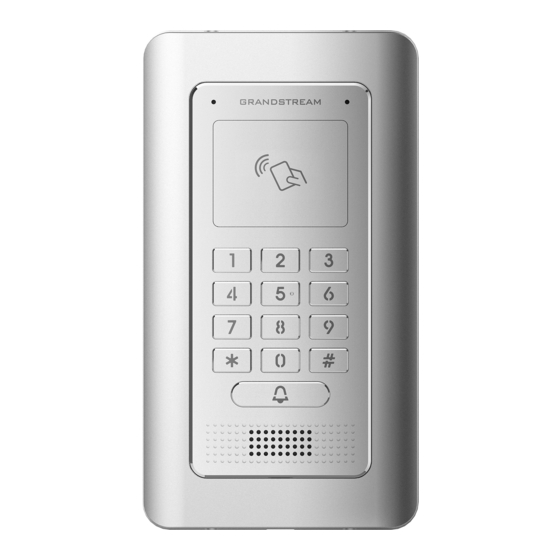
Page 16: Description Of The Gds3705
Description of the GDS3705 Below figures show the component of the back and front view of GDS3705 IP Audio Access Door System: Figure 2: GDS3705 Front View Figure 3: GDS3705 Back View Connecting and Setting up the GDS3705 The GDS3705 can be powered using PoE or PSU: Using PoE as power supply (Suggested) •... -
Page 17: Gds3705 Wiring Connection
J4 (Special) Black Both Input and Output MUST be connected 2.0mm WG_D1_OUT Orange Wiegand Output GDS3705 function as Output of Card Reader, Connect Pin 1, Signal 2, 3 WG_D0_OUT Brown Wiegand Output Blue For External Card Reader; Or GDS3705 as Receiver Only... -
Page 18: Gds3705 Back Cover Connections
Connection Example To connect the GDS either by using PoE or PSU follow steps below: • Open the Back-Cover Board of the GDS3705 which should look like following figure. Figure 5: GDS3705 Back Cover P a g e GDS3705 User Manual... -
Page 19: Power Gds3705 Using Poe
Use the TIA/EIA 568-B standard, which define pin-outs for using Unshielded Twisted Pair cable and RJ-45 connectors for Ethernet connectivity. Figure 6: Connection Example • Connect each wire of the cable to its associate on the Back Cover of the GDS3705 to power the unit using PoE. Power GDS3705 using PSU •... -
Page 20: Getting To Know Gds3705
HTML pages allow users to configure the GDS3705 through all available Web browsers in the internet. Connecting GDS3705 to Network with DHCP Server The GDS3705 by default has a DHCP client enabled, it will automatically get IP address from DHCP server. Windows Platform... -
Page 21: Gs Search
Figure 9: GDS3705 Login Page GS Search GS search is a program that is used to detect and capture the IP address of Grandstream devices. Below are instructions for using the “GS Search” utility tool: Download the GS Search utility tool from Grandstream website using the following link: http://www.grandstream.com/sites/default/files/Resources/GS_Search.zip... -
Page 22: Gds Manager Utility Tool
Double click on a device to access its webGUI. GDS Manager Utility Tool User can know the IP address assigned to the GDS3705 from DHCP server log or using the Grandstream GDS Manager after installing this free utility tool provided by Grandstream. User can find instructions below, for using “GDS Manager”... -
Page 23: Connect To The Gds3705 Using Static Ip
Connect to the GDS3705 using Static IP If there is no DHCP server in the network, or the GDS3705 does not get IP from DHCP server, user can connect the GDS3705 to a computer directly, using static IP to configure the GDS3705. -
Page 24: Figure 12: Static Ip On Windows
Figure 12: Static IP on Windows Power on the GDS3705, using PoE injector or external DC power. Enter 192.168.1.168 in the address bar of the browser, log in to the device with admin credentials. the default admin username is “admin” and the default random password can be found at the sticker on the GDS3705. -
Page 25: Gds3705 Application Scenarios
PoE Switch with related Cat5e/Cat6 wiring Peering using SIP Server (UCM6XXX) For large deployment, multiple GDS3705 units might be required, peered connection will not work in such case due to multiple connections. Such scenarios require an IPPBX or a SIP Proxy to accomplish the tasks. -
Page 26: Figure 13: Peering Gds3705 With Ucm6Xxx
Figure 13: Peering GDS3705 with UCM6XXX P a g e GDS3705 User Manual Version 1.0.0.20... -
Page 27: Gds3705 Peripheral Connections
GDS3705 PERIPHERAL CONNECTIONS Below is the illustration of GDS3705 peripheral connections for related applications. Figure 14: Peripheral Connections for GDS3705 P a g e GDS3705 User Manual Version 1.0.0.20... -
Page 28: Alarm In/Out
• The Alarm_In circuit, if there is any voltage change between 3V and 15V, as specified in the table above, the GDS3705 Alarm_In port will detect it and trigger the action and event. • Higher voltage and wrong polarity connection are prohibited because this will damage the devices. -
Page 29: Protection Diode
Protection Diode When connecting the GDS3705 to a door strike it is recommended to set an EMF protection diode in reverse polarity for a secure use, below examples of deployment for the protection diode. Figure 16: Protection Diode - Example 1 The reverse EMF protection diode must always be installed in reverse polarity across the door strike. -
Page 30: Wiring Sample Using 3 Rd Party Power Supply
Party Power Supply Figure 18: 3 party Power Supply Wiring Sample Wiring Sample using Power Supply for both GDS3705 and Electric Strike Figure 19: Power Supply used for both GDS3705 and Electric Strike P a g e GDS3705 User Manual... -
Page 31: Wiring Sample Using Poe To Power Gds3705 And 3 Rd Party Power Supply For Electric Strike
Wiring Sample using PoE to power GDS3705 and 3 Party Power Supply for Electric Strike Figure 20: Wiring Sample using PoE to power GDS3705 and 3 party Power Supply for Electric Strike Warning: The following example should be avoided when powering the electric strike. -
Page 32: Good Wiring Sample For Electric Strike And High-Power Device
Figure 22: Electric Strike and High-Power Device Example Wiegand Module Wiring Examples GDS3705 package is shipped with one Wiegand cable for Input/Output Wiegand connections. The following examples shows how to connect the Wiegand Input/Output devices to the GDS3705. Input example with 3rd party power supply for Wiegand device... -
Page 33: Input Example With Power Supply For Both Gds3705 And Wiegand Device
If power source is 12VDC, Wiegand device can share same power source of GDS3705. However, users need to check the max power consumption and the max capability of the power source. If Wiegand device is using 5VDC, GDS3705 Wiegand port can provide 5VDC with max 500mA to power up Wiegand device. -
Page 34: Output Example With 3 Rd Party Power Supply For Wiegand Device
Wiegand device Figure 25: Wiegand Output Wiring Example When the Wiegand output of the GDS3705 is connected, it acts as the signal receiver of the 3 party Wiegand device, connecting to door controller. The major wiring is GND, D0, and D1. Because usually the door controller will consume big current and power, the power supply should be separated. -
Page 35: Gds3705 Home Web Page
GDS3705 HOME WEB PAGE • Once the IP address of the GDS3705 is entered on the user browser, the login web page will pop up allowing user to configure the GDS3705 parameters. • When clicking on the “Language” drop down, supported languages will be displayed as shown in Figure below. -
Page 36: Gds3705 Settings
GDS3705 SETTINGS Door System Settings Users can configure system operations parameters, like input PIN for the door and manage users’ settings. Basic Settings Figure 28: Door System Settings Page P a g e GDS3705 User Manual Version 1.0.0.20... -
Page 37: Table 5: Door System Settings
• Peering mode: - User should configure multiple IP addresses of phones instead of SIP extensions, when Door Bell pressed the GDS3705 will ring the configured IP Addresses in Serial mode. Note: This field supports a Maximum of 256 characters. - Page 38 Configures PIN code stored in the GDS3705, remote SIP phone needs to Remote PIN to Open the input and match this PIN (the PIN is sent via DTMF while in call) so that Door the GDS3705 can open the door.
-
Page 39: Card Management
GDS3705 support RFID for multiple users to open door, therefore every user has its own PIN. For environment with 100 users and more, it’s difficult for the GDS3705 to manage all these users and a separate PC or Server should be involved for such kind of management and monitoring. -
Page 40: Add Users Manually
Notes: The GDS3705 can add up to 2000 card user. Press to import / export users’ configuration file, information and data stored on the GDS3705. to search for an entry on the Cards list. Add Users Manually To add users, click on , the following page will pop up. -
Page 41: Add Users Automatically
If [Enable Card Issuing Mode] is checked, the GDS3705 keypad will start blinking and once an RFID card is swiped, data stored on the card will be added into the GDS3705 card management page, user can still edit the entry added automatically by modifying some fields. -
Page 42: Group
Schedule The Schedule page allows to manage schedule time frames which will be assigned to the users for door system usage. Out of the configured time intervals, GDS3705 will not allow users to access. Click on to edit a schedule or for schedule details. -
Page 43: Holiday
The Holiday page allows to manage holidays which will be assigned to the users for door system usage. Click on to edit the holidays or for holiday details. Figure 34: Edit Holiday Time P a g e GDS3705 User Manual Version 1.0.0.20... -
Page 44: System Settings
Update Interval Configures the Interval (in minutes) to retrieve updates from the NTP server. Network Settings This page allows users to set either a static or DHCP IP address to access the GDS3705. P a g e GDS3705 User Manual... -
Page 45: Table 9: Basic Settings
Figure 36: Basic Settings Page Table 9: Basic Settings IP Address Mode Selects DHCP or Static IP. Default DHCP. (Static recommended) IP Address Configures the Static IP of the GDS3705. Subnet Mask Configures the Associated Subnet Mask. Gateway Configures the Gateway IP address. -
Page 46: Access Settings
Notes: • If the GDS3705 is behind SOHO (Small Office Home Office) router with port forwarding configured for remote access, static IP should be used to avoid IP address changes after router reboot. • TCP port above 5000 is suggested to Port forward HTTP for remote access, due to some ISP would block port 80 for inbound traffic. -
Page 47: User Management
Figure 39: Password Recovery Email SIP Settings SIP Basic Settings Basic Settings allow users to configure their SIP account. P a g e GDS3705 User Manual Version 1.0.0.20... -
Page 48: Table 12: Sip Basic Settings
E.164 number. If set to "Enable", "Tel:" will be used instead of "SIP:" in the SIP request. The default setting is "Disable". Authenticate Password Sets the Authenticate password used by SIP proxy. P a g e GDS3705 User Manual Version 1.0.0.20... -
Page 49: Sip Advanced Settings
Sets the registration expiration time. Default setting is 60 minutes. Register Expiration Sets the local SIP port. Default setting is 5060. Local SIP Port Sets the local RTP port for media. Default setting is 5004. Local RTP Port P a g e GDS3705 User Manual Version 1.0.0.20... -
Page 50: White List
This page allows users to configure the white list, which is a phone number or extension list that can call the GDS3705. (the call will be automatically answered when calling from a phone set on the white list). P a g e GDS3705 User Manual Version 1.0.0.20... -
Page 51: Audio Settings
This page allows users to configure the audio settings. Figure 43: Audio Settings Page Table 15: Audio Settings Preferred Audio Configures the audio codec. Three codecs are available: Codec PCMU, PCMA and G.722. P a g e GDS3705 User Manual Version 1.0.0.20... -
Page 52: Alarm Config
Alarm Config This page allows users to configure alarm schedule and alarm actions. Alarm Events Config This page allows users to configure GDS3705 events to trigger programmed actions within predefined schedule. Figure 44: Events Page Alarm can be triggered by GDS3705 input. -
Page 53: Digital Input 1
5,10,15,20,25 and 30 seconds. Silently Alarm Mode If Silently Alarm Mode is enabled, GDS3705 will disable alarm sound and background light for specified alarms types (Digital Input) when they are triggered. Note: This option affects only alarm sound/light, other actions will still be applied. -
Page 54: Hostage Code
Note: No sound alarm will be triggered in this mode. Tamper Alarm Tamper alarm is anti-hack from Hardware level. When this option is checked, if the GDS3705 is removed from the installation board, it will trigger configured alarm actions. There is an embedded mechanism on the GDS3705 that allows it to detect when the it is removed. -
Page 55: Alarm Schedule
Note: Schedule must be configured first to allow the alarm to take the related action. Figure 46: Alarm Schedule GDS3705 supports up to 10 alarm schedules to be configured, with time span specified by users. User can edit the alarm schedule by clicking button. -
Page 56: Alarm Action
Figure 47: Edit Schedule Alarm Action This page specifies the configuration of Profile used by the Alarm Actions. A Profile is required before the Alarm Action can take effect. P a g e GDS3705 User Manual Version 1.0.0.20... -
Page 57: Table 21: Alarm Actions
Upload to Alarm Center If selected, the GDSManager will popup alarm window and sound alarm in the computer speaker. Voice Alarm to SIP If selected, GDS3705 will call pre-configured phone and will play sound Phone alarm. Send Email If selected, an email with snapshot will be sent to the pre-configured email destination. -
Page 58: Alarm Phone List
Once the event is triggered (Motion Detection, Door Bell Pressed…), the GDS3705 will call the first number, once time out is reached and no answer is returned from the first number, the GDS3705 will try the next number on the list and so on. Once the remote phone answers the call, an alarm will be played to notify users that an event is triggered. -
Page 59: Maintenance Settings
Click “Email Test” after configuration, if settings are correct, a test email will send out and “E-mail test successfully” message on the top page will appear Maintenance Settings This page shows the GDS3705 Maintenance parameters. Upgrade This page contains the upgrade parameters of the GDS3705. P a g e GDS3705 User Manual Version 1.0.0.20... -
Page 60: Table 24: Upgrade
Specifies the upgrade interval in minutes. DHCP Option 66 Override Activates DHCP option 66 to override upgrade/config servers. Server Zero Config Enables Zero Config feature for auto provisioning. Automatic Upgrade Enables automatic upgrade and provisioning. P a g e GDS3705 User Manual Version 1.0.0.20... -
Page 61: Reboot & Reset
Reset There are two options for the reset function. Clear All Data All data will be reset, GDS3705 will be set to factory default. Retain Network Data Only All data will be erased except for Network data like IP address…... -
Page 62: Data Maintenance
• Five levels of Debugging are available, None, Debug, Info, Warning, Error. • Once the Syslog Server and the level entered, press “Save” and then Reboot the GDS3705 to apply the settings. Data Maintenance This page allows users to manage the GDS3705 configuration file by importing / exporting the configuration files. -
Page 63: Status
Figure 55: Data Maintenance Page Click on to save the GDS3705 configuration in a predefined directory. Note: Users can either select to include all the passwords (SIP, FTP, Remotes access…) on the configuration files exported or not including the passwords as displayed on the previous figure. -
Page 64: Network Info
RootFS Version Displays the RootFS Version. Prog Version Displays the Prog Version. System Up Time Since Displays the time since the first boot of the GDS3705. Notes: • When the SIP account is registered, the status display will be Online •... -
Page 65: Table 27: Network Info
MAC Address Displays the GDS3705 MAC Address. IP Address Mode Displays the IP address mode used. IP Address Displays the IP address of the GDS3705. Subnet Mask Displays the Subnet Mask used. Gateway Displays the GDS3705 Gateway. DNS Server 1 Displays the Preferred DNS Server. -
Page 66: Factory Reset
Figure 58: Reset via Web GUI Hard Factory Reset Some users did not keep the revised password safely and forgot the changed password. Due to GDS3705 did NOT have built-in reset button (Grandstream purposely designed this way to enhance security), this will make the GDS3705 inaccessible even for the true owner who lost the changed password. -
Page 67: Figure 59: Wiegand Interface Cable
Figure 59: Wiegand Interface Cable To perform hard factory reset to the GDS3705, please refer to following steps 1. Power OFF the GDS3705. 2. Take the provided Wiegand cable, connect (or shorting) the related color wires as illustrated on the following picture. - Page 68 User who wants to do hard factory reset has to perform the operation from the beginning again. After 3 ~ 5 minutes the GDS3705 will finish performing the reset process, then the user can log into the GDS3705 web GUI using the shipped default password.
-
Page 69: Experiencing The Gds3705
EXPERIENCING THE GDS3705 Please visit our website: http://www.grandstream.com to receive the most up-to-date updates on firmware releases, additional features, FAQs, documentation and news on new products. We encourage you to browse our product related documentation, FAQs and User and Developer Forum answers to your general questions.