Grandstream Networks GDS3705 User Manual
Audio door access system
Hide thumbs
Also See for GDS3705:
- User manual (69 pages) ,
- Quick installation manual (13 pages) ,
- Quick reference manual (10 pages)
Table of Contents
Advertisement
Quick Links
Advertisement
Table of Contents

Related Manuals for Grandstream Networks GDS3705


Summary of Contents for Grandstream Networks GDS3705
- Page 1 Grandstream Networks, Inc. GDS3705 Audio Door Access System User Manual...
- Page 2 Grandstream Networks, Inc. is not permitted. The latest electronic version of this user manual is available for download here: http://www.grandstream.com/support Grandstream is a registered trademark and Grandstream logo is trademark of Grandstream Networks, Inc. in the United States, Europe and other countries. CAUTION Changes or modifications to this product not expressly approved by Grandstream, or operation of this product in any way other than as detailed by this User Manual, could void your manufacturer warranty.
- Page 3 Increase the separation between the equipment and receiver. • Connect the equipment into an outlet on a circuit different from that to which the receiver is connected. • Consult the dealer or an experienced radio/TV technician for help. P a g e GDS3705 User Manual Version 1.0.1.16...
- Page 4 125 KHz Channel Number: Antenna Type / Gain: Internal Type of Modulation: Operation temperature: -30 °C ~ +60 °C Storage temperature: -35 °C ~ +60 °C Humidity: 10 ~ 90% non-condensing P a g e GDS3705 User Manual Version 1.0.1.16...
- Page 5 GNU GPL INFORMATION GDS3705 firmware contains third-party software licensed under the GNU General Public License (GPL). Grandstream uses software under the specific terms of the GPL. Please see the GNU General Public License (GPL) for the exact terms and conditions of the license.
-
Page 6: Table Of Contents
Technical Specifications ........................19 GETTING STARTED ..................... 21 Equipment Packaging ........................21 Description of the GDS3705 ......................22 Connecting and Setting up the GDS3705 ..................22 GDS3705 Wiring Connection ......................23 GDS3705 Back Cover Connections ....................24 Connection Example ........................24 Power GDS3705 using PoE ..................... - Page 7 Wiegand device ..........40 Wiegand RFID Card Reader Example..................40 Siren alarming when door opened abnormally................. 41 GDS3705 Connection: IN2 set as Normal Close and “Fail Safe” Electric Strike using 3 Party Power Supply .......................... 41 GDS3705 Connection: IN2 set as Normal Open and “Fail Secure”...
- Page 8 Door opening with SIP Call ...................... 44 Door opening without SIP Call ....................44 Secure Open Door via GDS3705/GSC3570 Peering ............... 45 GDS3705 HOME WEB PAGE..................48 GDS3705 SETTINGS ....................49 Door System Settings ........................49 Basic Settings .......................... 49 Using Alarm Out (COM 1) to Control a Second Door ................
- Page 9 Status ............................101 Account Status ........................101 System Info ........................... 101 Network Info .......................... 103 FACTORY RESET ...................... 105 Restore to Factory Default Via Web GUI ..................105 Hard Factory Reset........................105 P a g e GDS3705 User Manual Version 1.0.1.16...
- Page 10 Reset Factory Password Via Special Key Combination Operation ..........108 EXPERIENCING THE GDS3705 ................110 Table of Tables Table 1: GDS3705 Features in a Glance ....................19 Table 2: GDS3705 Technical Specifications ................... 19 Table 3: Equipment Packaging ....................... 21 Table 4: GDS3705 Wiring Connection ....................
- Page 11 Figure 23: Wiegand Input Example with 3 party Power Supply ............. 38 Figure 24: Wiegand Input Example with Power Supply for GDS3705 and Wiegand Device ....39 Figure 25: Wiegand Output Wiring Example ................... 40 Figure 26: Wiegand RFID Card Reader Example ................... 40 Figure 27: Digital Input set as Normal close ...................
- Page 12 Figure 76: Email Settings - SMTP Page ....................92 Figure 77: Upgrade Page........................93 Figure 78: Reset & Reboot Page ......................94 Figure 79: Debug Log Page ........................95 Figure 80: Data Maintenance Page ......................96 P a g e GDS3705 User Manual Version 1.0.1.16...
- Page 13 Figure 86: System Info Page........................ 102 Figure 87: Network Info Page ......................103 Figure 88: Reset via Web GUI ......................105 Figure 89: Wiegand Interface Cable ..................... 106 Figure 90: Wiegand Cable Connection ....................106 P a g e GDS3705 User Manual Version 1.0.1.16...
-
Page 14: Change Log
CHANGE LOG This section documents significant changes from previous versions of user manual for GDS3705. Only major new features or major document updates are listed here. Minor updates for corrections or editing are not documented here. Firmware Version 1.0.1.16 ... -
Page 15: Firmware Version 1.0.0.41
Enhanced security by only allowing numbers existing under “White List” to open the door remotely when call is initiated from GDS3705. [Remote PIN to Open the Door] Added option to synchronize Keep Door Open from GDSManager version 1.0.1.1 or later. [Central Mode] Firmware Version 1.0.0.37... -
Page 16: Firmware Version 1.0.0.35
Added Support for system events notification via HTTP. [Event Notification] Added Factory Functions for Audio Loopback and Certificate Verification. [Factory Functions] Firmware Version 1.0.0.20 This is the initial version for GDS3705. P a g e GDS3705 User Manual Version 1.0.1.16... -
Page 17: Document Purpose
DOCUMENT PURPOSE This document describes the basic concept and tasks necessary to use and configure your GDS3705. And it covers the topic of connecting and configuring the GDS3705, making basic operations and the call features. Please visit http://www.grandstream.com/support to download the latest “GDS3705 User Manual”. -
Page 18: Welcome
GDS3705 IP Audio Door Access System can be managed by Grandstream’s free windows-based management software: GDS Manager is a client/server based software which provided RFID card management and basic reports for the door entrance. GDS3705 is ideal for entry places such as banks, hotels, schools, office buildings, retail stores and small warehouses. -
Page 19: Product Overview
PRODUCT OVERVIEW Feature Highlights The following table contains the major features of the GDS3705. Table 1: GDS3705 Features in a Glance 4 SIP accounts and 4 lines. Broad interoperability with most 3 party SIP/VoIP devices and leading SIP/NGN/IMS platforms. - Page 20 CE: EN 55032; EN 50130; EN 61000-3-2; EN 61000-3-3; EN 60950-1; EN 300 330; EN 301 489-1; EN 301 489-3; EN 62311 Compliance RCM: AS/NZS CISPR 22/24; AS/NZS 4268; AS/NZS 60950.1 IC: ICES-003; RSS310 P a g e GDS3705 User Manual Version 1.0.1.16...
-
Page 21: Getting Started
GETTING STARTED This chapter provides basic installation instructions including the list of the packaging contents and information for obtaining the best performance using the GDS3705 Audio Access Door System. Equipment Packaging Table 3: Equipment Packaging 1 x GDS3705 1 x Wiegand Cable ... -
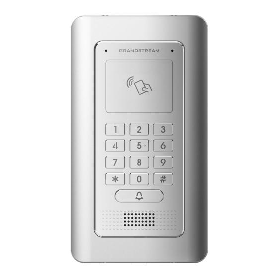
Page 22: Description Of The Gds3705
Description of the GDS3705 Below figures show the component of the back and front view of GDS3705 IP Audio Access Door System: Figure 2: GDS3705 Front View Figure 3: GDS3705 Back View Connecting and Setting up the GDS3705 The GDS3705 can be powered using PoE or PSU: Using PoE as power supply (Suggested) ... -
Page 23: Gds3705 Wiring Connection
J4 (Special) Black Both Input and Output MUST be connected 2.0mm WG_D1_OUT Orange Wiegand Output GDS3705 function as Output of Card Reader, Connect Pin 1, Signal 2, 3 WG_D0_OUT Brown Wiegand Output Blue For External Card Reader; Or GDS3705 as Receiver Only... -
Page 24: Gds3705 Back Cover Connections
Connection Example To connect the GDS either by using PoE or PSU follow steps below: Open the Back-Cover Board of the GDS3705 which should look like following figure. Figure 5: GDS3705 Back Cover P a g e GDS3705 User Manual... -
Page 25: Power Gds3705 Using Poe
Use the TIA/EIA 568-B standard, which define pin-outs for using Unshielded Twisted Pair cable and RJ-45 connectors for Ethernet connectivity. Figure 6: Connection Example Connect each wire of the cable to its associate on the Back Cover of the GDS3705 to power the unit using PoE. Power GDS3705 using PSU ... -
Page 26: Getting To Know Gds3705
HTML pages allow users to configure the GDS3705 through all available Web browsers in the internet. Connecting GDS3705 to Network with DHCP Server The GDS3705 by default has a DHCP client enabled, it will automatically get IP address from DHCP server. Windows Platform... -
Page 27: Gs Search
Figure 9: GDS3705 Login Page GS Search GS search is a program that is used to detect and capture the IP address of Grandstream devices. Below are instructions for using the “GS Search” utility tool: Download the GS Search utility tool from Grandstream website using the following link: http://www.grandstream.com/sites/default/files/Resources/GS_Search.zip... -
Page 28: Gds Manager Utility Tool
Double click on a device to access its webGUI. GDS Manager Utility Tool User can know the IP address assigned to the GDS3705 from DHCP server log or using the Grandstream GDS Manager after installing this free utility tool provided by Grandstream. User can find instructions below, for using “GDS Manager”... -
Page 29: Connect To The Gds3705 Using Static Ip
Connect to the GDS3705 using Static IP If there is no DHCP server in the network, or the GDS3705 does not get IP from DHCP server, user can connect the GDS3705 to a computer directly, using static IP to configure the GDS3705. -
Page 30: Figure 12: Static Ip On Windows
Figure 12: Static IP on Windows Power on the GDS3705, using PoE injector or external DC power. Enter 192.168.1.168 in the address bar of the browser, log in to the device with admin credentials. the default admin username is “admin” and the default random password can be found at the sticker on the GDS3705. -
Page 31: Gds3705 Application Scenarios
PoE Switch with related Cat5e/Cat6 wiring Peering using SIP Server (UCM6XXX) For large deployment, multiple GDS3705 units might be required, peered connection will not work in such case due to multiple connections. Such scenarios require an IPPBX or a SIP Proxy to accomplish the tasks. -
Page 32: Figure 13: Peering Gds3705 With Ucm6Xxx
Figure 13: Peering GDS3705 with UCM6XXX P a g e GDS3705 User Manual Version 1.0.1.16... -
Page 33: Gds3705 Peripheral Connections
GDS3705 PERIPHERAL CONNECTIONS Below is the illustration of GDS3705 peripheral connections for related applications. Figure 14: Peripheral Connections for GDS3705 P a g e GDS3705 User Manual Version 1.0.1.16... -
Page 34: Alarm In/Out
The Alarm_In circuit, if there is any voltage change between 3V and 15V, as specified in the table above, the GDS3705 Alarm_In port will detect it and trigger the action and event. Higher voltage and wrong polarity connection are prohibited because this will damage the devices. -
Page 35: Protection Diode
Protection Diode When connecting the GDS3705 to a door strike it is recommended to set an EMF protection diode in reverse polarity for a secure use, below examples of deployment for the protection diode. Figure 16: Protection Diode - Example 1 The reverse EMF protection diode must always be installed in reverse polarity across the door strike. -
Page 36: Wiring Sample Using 3 Rd Party Power Supply
Party Power Supply Figure 18: 3 party Power Supply Wiring Sample Wiring Sample using Power Supply for both GDS3705 and Electric Strike Figure 19: Power Supply used for both GDS3705 and Electric Strike P a g e GDS3705 User Manual... -
Page 37: Wiring Sample Using Poe To Power Gds3705 And 3 Rd Party Power Supply For Electric Strike
Wiring Sample using PoE to power GDS3705 and 3 Party Power Supply for Electric Strike Figure 20: Wiring Sample using PoE to power GDS3705 and 3 party Power Supply for Electric Strike Warning: The following example should be avoided when powering the electric strike. -
Page 38: Good Wiring Sample For Electric Strike And High-Power Device
Figure 22: Electric Strike and High-Power Device Example Wiegand Module Wiring Examples GDS3705 package is shipped with one Wiegand cable for Input/Output Wiegand connections. The following examples shows how to connect the Wiegand Input/Output devices to the GDS3705. Input example with 3... -
Page 39: Input Example With Power Supply For Both Gds3705 And Wiegand Device
If power source is 12VDC, Wiegand device can share same power source of GDS3705. However, users need to check the max power consumption and the max capability of the power source. If Wiegand device is using 5VDC, GDS3705 Wiegand port can provide 5VDC with max 500mA to power up Wiegand device. -
Page 40: Output Example With 3 Rd Party Power Supply For Wiegand Device
Wiegand device Figure 25: Wiegand Output Wiring Example When the Wiegand output of the GDS3705 is connected, it acts as the signal receiver of the 3 party Wiegand device, connecting to door controller. The major wiring is GND, D0, and D1. Because usually the door controller will consume big current and power, the power supply should be separated. -
Page 41: Siren Alarming When Door Opened Abnormally
3) Open Door using PIN (either public PIN or private PIN) Once alarm triggered, the GDS3705 will play siren sound, send email to administrator (if configured SMTP); call the configured alarm SIP phone, send the alarm output (if connected). User will only be able to disable the siren using the 3 methods mentioned above. -
Page 42: Gds3705 Connection: In2 Set As Normal Open And "Fail Secure" Electric Strike Using 3 Rd Party Power Supply
Figure 28: “Fail safe” Electric Strike using 3rd Party Power Supply GDS3705 Connection: IN2 set as Normal Open and “Fail Secure” Electric Strike using 3 Party Power Supply Figure 29: Digital Input set as Normal open Figure 30: “Fail Secure” Electric Strike using 3rd Party Power Supply... -
Page 43: Open Door Via Gds3705 With Or Without A Sip Call
GDS3705: 1.0.1.16 or higher. From GDS3705 side, the configuration is the same. Only difference is the number of doors to be controlled: If using Local Relay controlled by GDS3705, TWO DOORS can be controlled. If using GSC3570 Relay, ONLY ONE DOOR can be controlled. The PIN and other settings are the same as SIP remote open door or GSC3570 secure open door. -
Page 44: Door Opening With Sip Call
Figure 32: GSC3570 Configuration Example Door opening with SIP Call When GSC3570 established call with GDS3705, the screen will display virtual open door button(s), and user will press the button to open door: Figure 33: Open Door with SIP Call Door opening without SIP Call At the GSC3570 idle screen, press “Monitor →Door system”, the related GDS305 will be displayed. -
Page 45: Secure Open Door Via Gds3705/Gsc3570 Peering
This secure open door feature need to include GSC3570 to make it a whole solution. The GDS3705/GSC3570 will be peering together in LAN/WAN via IP/SIP, the door lock/strike will be wired to GSC3570Alarm_Out port and controlled by GSC3570. This way the strike control is inside the building with enhanced security. -
Page 46: Figure 36: Gsc3570 Secure Open Door Via Gds3705
For “Secure Open Door”, the GSC3570 is pairing with GDS3705. The GSC3570 controlling the relay/strike/lock from inside the building (Unlike GDS3705 installed outside), but only ONE door can be controlled because GSC3570 only has one Relay Control circuit build in. This pairing can be via LAN/WAN but LAN is recommended and actually most of the application scene are in LAN environment because most likely the GSC3570 and GDS37xx are in the same building. -
Page 47: Figure 37: Gds3505 Web Gui Configuration For Secure Open Door With Gsc3570
Figure 37: GDS3505 Web GUI configuration for secure open door with GSC3570 GSC3570 Web Configuration The GSC3570 side also need to be configured accordingly, like below example: Figure 38: GSC3570 Web GUI configuration for secure open with GDS3705 Notes: ... -
Page 48: Gds3705 Home Web Page
GDS3705 HOME WEB PAGE Once the IP address of the GDS3705 is entered on the user browser, the login web page will pop up allowing user to configure the GDS3705 parameters. When clicking on the “Language” drop down, supported languages will be displayed as shown in Figure below. -
Page 49: Gds3705 Settings
GDS3705 SETTINGS Door System Settings Users can configure system operations parameters, like input PIN for the door and manage users’ settings. Basic Settings Figure 40: Door System Settings Page P a g e GDS3705 User Manual Version 1.0.1.16... -
Page 50: Table 5: Door System Settings
Webrelay. Local Relay: Local Relay is the GDS3705 controlling the relay. The strike is wired into the COM2 or COM1 port of the GDS3705 depending 1 door or 2 door need to be controlled. Webrelay: When Webrelay is selected, customers need to... - Page 51 “Door 2” ALMOUT1 Feature (the two functions are mutual exclusive). When option “Open Door” is selected, will enable GDS3705 to control the operation of two doors via RFID, local and remote PINs. ALMOUT1 Status Select Normal Open or Normal Close depending on the lock used.
- Page 52 - The field can be configured to store multiple one or multiple SIP extensions, if configured with multiple extensions (ex: 1001, 1002, 1003), separated with “,” the GDS3705 will ring one extension after the other in a Serial Hunting Mode (GDS will ring each extension by default 15 seconds, this can be changed on the Ring Timeout) or ring them simultaneously in Parallel Hunting Mode.
- Page 53 Number Dialing]. Unified PIN: Means all members share a same PIN to unlock the door. Users need to enter the following sequence from the GDS3705 keypad to open the door [*Local PIN to Open Door#]. Card & Private PIN: Means every member needs to swipe his card...
- Page 54 Configures PIN stored in GDS3705, input locally this PIN on the GDS3705 keypad will unlock the door. This feature needs Private PIN, means every member has a private PIN, the GDS will record who unlocked the door every time. Local PIN to Open Door Users need to enter the following sequence from the GDS3705 to open the door [*Virtual Number*Private PIN#].
- Page 55 PIN will be shown in the log. Enables RFID card issuing/program into the GDS3705. When selected Enable Card Issuing Mode sweeping an RFID card into the GDS3705 will add card information into. [Card Management] Card issuing State Expire Card issuing mode will be automatically disabled when timer reached (The Time(m) range of value is 1 –...
-
Page 56: Using Alarm Out (Com 1) To Control A Second Door
Wiegand Input device or GDS3705 can be installed at Door2 with related cable wired into the control GDS3705 installed at Door1. The Door1 and Door2 can be configured to be open by programmed RFID cards, PINs either separately or both. -
Page 57: Figure 42: Universal Local Pin
For above example, the GDS3705 is configured to control Door1 (wiring to COM2 interface); the 3 party Wiegand Input is set to control Door2 (wiring to COM1 interface). In case of a power loss then the DOOR STATUS when power is off will be depending on the following situations: ... -
Page 58: Figure 43: Remote Pin To Open Door
Note: For enhanced security, When call is initiated from GDS then only the numbers existing in “Number Called When Door Bell Pressed”, “Account White Lists” or “Card Management” will be able to use DTMF PIN to open door remotely. Figure 43: Remote PIN to Open Door P a g e GDS3705 User Manual Version 1.0.1.16... -
Page 59: Figure 44: Right Of Card And Private Pin
For all the settings, the final result of which door can be opened is the LOGIC INTERSECT OPERATON of ALL the sets of condition qualified. Please refer to our Open Door Flow chart for better understanding on how to configure and control 2 Doors operation: http://firmware.grandstream.com/GDS3710_opendoors_logic.pdf P a g e GDS3705 User Manual Version 1.0.1.16... -
Page 60: Keep Door Open
Select the Keep Door Open mode. Set the amount of time in minutes where the door will keep opened. Click Interval of Keep Door Open (min) to open door immediately. 2- Schedule Open Door (Repeated Action) P a g e GDS3705 User Manual Version 1.0.1.16... -
Page 61: Table 7: Schedule Keep Door Open
Users can specify which Holiday Schedule to be included into the Keep Door Holiday Mode Open schedule Click on Edit schedule to select which periods for each day the door will remain open, as shown on below screenshot. Figure 48: Modify Schedule P a g e GDS3705 User Manual Version 1.0.1.16... -
Page 62: Card Management
This page allows users to add information about RFID cards, two options are possible either add RFID cards manually or automatically. Figure 49: Card Management Notes: The GDS3705 can add up to 2000 card user. Press to import / export users’ configuration file, information and data stored on the GDS3705. -
Page 63: Table 8: Card Info
When “card issuing mode” is enabled, this filed will be added automatically. Valid Start Date Configures the start date of validity of the RFID card. Valid End Date Configures the End date of validity of the RFID card. P a g e GDS3705 User Manual Version 1.0.1.16... -
Page 64: Add Users Automatically
If [Enable Card Issuing Mode] is checked, the GDS3705 keypad will start blinking and once an RFID card is swiped, data stored on the card will be added into the GDS3705 card management page, user can still edit the entry added automatically by modifying some fields. -
Page 65: Group
Schedule The Schedule page allows to manage schedule time frames which will be assigned to the users for door system usage. Out of the configured time intervals, GDS3705 will not allow users to access. Click on to edit a schedule or for schedule details. -
Page 66: Holiday
Note: The GDS3705 supports up to 10 schedules. Figure 53: Edit Schedule Time Holiday The Holiday page allows to manage holidays which will be assigned to the users for door system usage. Click on to edit the holidays or for holiday details. -
Page 67: System Settings
This page allows users to configure date and time, network settings as well as access method to the GDS3705 and password for accessing the Web GUI. Date & Time Settings This page allows users to adjust system date and time of the GDS3705. Figure 55: Date & Time Page P a g e GDS3705 User Manual Version 1.0.1.16... -
Page 68: Network Settings
Configures the Interval (in minutes) to retrieve updates from the NTP server. Network Settings This page allows users to set either a static or DHCP IP address to access the GDS3705. Figure 56: Basic Settings Page P a g e GDS3705 User Manual Version 1.0.1.16... -
Page 69: Openvpn® Settings
Priority Value Notes: If the GDS3705 is behind SOHO (Small Office Home Office) router with port forwarding configured for remote access, static IP should be used to avoid IP address changes after router reboot. TCP port above 5000 is suggested to Port forward HTTP for remote access, due to some ISP would block port 80 for inbound traffic. -
Page 70: Figure 57: Openvpn Settings Page
The cipher method of OpenVPN®, must be the same cipher method used by the Method OpenVPN® server. Supported methods are: Blowfish, AES-128, AES-256 and Triple-DES. OpenVPN® Configures the OpenVPN® authentication username (optional). Username P a g e GDS3705 User Manual Version 1.0.1.16... -
Page 71: Access Settings
Selects the access mode to the webGUI either HTTP or HTTPS. Web Access Port Specifies the TCP port for Web Access, default 443. If no action is made within this time the GDS3705 will logout from the User Login Timeout(min) Web GUI, range is between 3 and 60. -
Page 72: User Management
1. Re-provisioned by ITSP or Service Provider (by adjusting the related parameters) 2. Hard Reset (GDS3705 has to be offline and uninstalled to perform this hard reset). Enable UPnP Discovery UPnP (or mDNS) function for local discovery. Default setting is enabled. -
Page 73: Table 13: User Management
To recover lost password, users can from the login page click on Forgot Password? Figure 60: Recover Password Click the link will pop up the following page to ask to input the “Email Address” for the Recover Password to be sent to: P a g e GDS3705 User Manual Version 1.0.1.16... -
Page 74: Factory Functions
Factory Functions Users could access factory functions in order to diagnosis the hardware and software of the unit like verifying the audio loopback and certificates verification. P a g e GDS3705 User Manual Version 1.0.1.16... -
Page 75: Account
This is used to validate certificate chain for the server’s certificate. Account The GDS3705 supports 4 SIP accounts and 4 lines, this section covers the configuration of basic and advanced SIP settings for each SIP account. Account 1 - 4... -
Page 76: Table 15: Sip Account Basic & Advanced Settings
If a symmetric NAT is detected, STUN will not work and only an outbound proxy can provide a solution. Configures the backup outbound proxy to be used when the “Outbound Backup Outbound Proxy Proxy” registration fails. By default, this field is left empty. P a g e GDS3705 User Manual Version 1.0.1.16... - Page 77 Password Note: For security reasons, the SIP password is invisible on the web UI. The GDS3705 is an audio only device, unlike GDS3710, user cannot see who in at the door. Adding this “Display Name” will also allow user receiving Display Name calls from GDS3705 knowing where the call is coming from (e.g.: which...
- Page 78 Users could select the mechanism from No, STUN, Keep-alive, UPnP, Auto or VPN. The default setting is “No”. If set to “STUN” and STUN server is configured, the GDS3705 will route according to the STUN server. If NAT type is Full Cone, Restricted Cone or...
-
Page 79: Phone Settings
The default setting is 2. Range is from 1-64. Phone Settings The phone settings allow users to configure the GDS3705 phone settings and the White list for all the SIP accounts. Phone Settings This page allows users to configure the GDS3705 phone settings. -
Page 80: Table 16: Phone Settings
SIP call. Default setting is 300. Specifies the Ring timeout, when no reply is returned from the called party after exceeding this field, the GDS3705 will hang up the call. The value is Ring Timeout(s) in the range of 0s – 90s. By default; it is “30” seconds. -
Page 81: Account [1-4] White List
This page allows users to configure the white list per account, which is a phone number or extension list that can call the GDS3705. (The call will be automatically answered when calling from a phone set on the white list, and all other inbound calls will be blocked), the user can configure up to 30 white phone numbers per SIP account. -
Page 82: Audio Settings
User can check this option in order to use the custom Doorbell Ringtone. Doorbell Ringtone Default Ringtone is used when this option is disabled. Tool This button will redirect user to our Grandstream Ringtone Generator tool in our website. P a g e GDS3705 User Manual Version 1.0.1.16... -
Page 83: Alarm Config
Note: Empty audio file is not accepted. Alarm Config This page allows users to configure alarm schedule and alarm actions. Alarm Events Config This page allows users to configure GDS3705 events to trigger programmed actions within predefined schedule. Figure 67: Events Page P a g e GDS3705 User Manual Version 1.0.1.16... -
Page 84: Input Digit
If set to Normal Close: Configured alarm will be triggered when Digital Input Status switch from Open to Close. By default, Input Digit 1 Status is “Disabled”. Select Schedule 1 Selects the predefined Alarm Schedule. P a g e GDS3705 User Manual Version 1.0.1.16... -
Page 85: Alarm Output
5,10,15,20,25 and 30 seconds. Silently Alarm Mode If Silently Alarm Mode is enabled, GDS3705 will disable alarm sound and background light for specified alarms types (Digital Input) when they are triggered. Note: This option affects only alarm sound/light, other actions will still be applied. -
Page 86: Hostage Code
Note: No sound alarm will be triggered in this mode. Tamper Alarm Tamper alarm is anti-hack from Hardware level. When this option is checked, if the GDS3705 is removed from the installation board, it will trigger configured alarm actions. There is an embedded mechanism on the GDS3705 that allows it to detect when the unit is removed. -
Page 87: Alarm Schedule Settings
Note: Schedule must be configured first to allow the alarm to take the related action. Figure 69: Alarm Schedule GDS3705 supports up to 10 alarm schedules to be configured, with time span specified by users. User can edit the alarm schedule by clicking button. -
Page 88: Alarm Action When Illegal Card Swiped
This option can be enabled from the web GUI, under Alarm Settings → Alarm Event Config Figure 71: Enable Non-authorized RFID Card Access Alarm Any illegal card swiped trying to access the door will trigger alarm based on user’s configuration, like below: P a g e GDS3705 User Manual Version 1.0.1.16... -
Page 89: Alarm Action Settings
Alarm Action Settings This page specifies the configuration of Profile used by the Alarm Actions. A Profile is required before the Alarm Action can take effect. Figure 73: Alarm Action P a g e GDS3705 User Manual Version 1.0.1.16... -
Page 90: Alarm Phone List
This page allows users to configure the Alarm Phone List, which are phone numbers or extensions list that the GDS3705 will call out when event is trigged (e.g.: doorbell pressed), the administrator can configure up to 10 phone numbers to be called and specify the SIP account to trigger the alarm call. -
Page 91: Email Settings
Once the event is triggered (Door Bell Pressed…), the GDS3705 will call the first number, once time out is reached and no answer is returned from the first number, the GDS3705 will try the next number on the list and so on. Once the remote phone answers the call, an alarm will be played to notify users that an event is triggered. -
Page 92: Maintenance Settings
Click “Email Test” after configuration, if settings are correct, a test email will send out and “E-mail test successfully” message on the top page will appear Maintenance Settings This page shows the GDS3705 Maintenance parameters. P a g e GDS3705 User Manual... -
Page 93: Upgrade
Upgrade This page contains the upgrade parameters of the GDS3705. Figure 77: Upgrade Page Table 28: Upgrade Upgrade Via Selects the upgrade method (HTTP, HTTPS). Firmware Server Path Configures the IP address or the FQDN of the upgrade server. Config Server Path Configures the IP address or the FQDN of the configuration server. -
Page 94: Reboot & Reset
If this option is checked, the Device will not challenge NOTIFY with 401. Authentication Default setting is Enabled. Reboot & Reset This page allows user to reboot (scheduled or immediate) and reset the GDS3705. Figure 78: Reset & Reboot Page Table 29: Reset & Reboot Reboot When clicked, the GDS3705 will restart (soft reboot). -
Page 95: Debug Log
Five levels of Debugging are available, None, Debug, Info, Warning, Error. Once the Syslog Server and the level entered, press “Save” and then Reboot the GDS3705 to apply the settings. Data Maintenance This page allows users to manage the GDS3705 configuration file by importing / exporting the configuration files. -
Page 96: System Health Alert
Figure 80: Data Maintenance Page Click on to save the GDS3705 configuration in a predefined directory. Note: Users can either select to include all the passwords (SIP, Remotes access…) on the configuration files exported or not including the passwords as displayed on the previous figure. -
Page 97: Event Notification
Event Notification This page allows users to configure the event notification details that will be used by GDS3705 to communicate to an HTTP server and Log Events. When the feature Enable and Configured, all the event logs will be uploaded to server: RFID open door, PIN open door, SIP Call, Alarm, etc... -
Page 98: Event Log
Or, the GDS3705, after making a Call, when doorbell pressed, will send to the configured HTTP server the following HTTP POST containing “Phone call” event: POST/HTTP/1.1 Host:192.168.6.107 Authorization:BasicOg== Connection:keep-alive Content-Length:62 Date: 2017-11-09; Time: 14:13:12; Event describe: Phone call. These HTTP POST messages can be used by a 3 party software to integrate the GDS3705. -
Page 99: Certificates
Figure 83: Event Log For more information about event logs, please visit this guide. Notes: The maximum size of log storage space of GDS3705 is about 3M. The size of each event log is 48 bytes. If the log data exceeded the maximum storage space, then the oldest log will be automatically released which will be 128K of old data. -
Page 100: Figure 84: Upload Certificate Files
“Issued by” and “Expiration date”. User could press to delete one of the files. P a g e GDS3705 User Manual Version 1.0.1.16... -
Page 101: Status
Status This page displays GDS3705 accounts, system and network information. Account Status This page displays of configured accounts’ SIP user ID, SIP server as well as the SIP Registration status, from Account 1 to Account 4. Notes: When the SIP account is registered, the SIP Registration status display will be Online ... -
Page 102: Table 31: System Info
Displays the Base Version. Prog Version Displays the Prog Version. System UpTime Displays the time since the first boot of the GDS3705. Click the button to check whether the firmware in the Firmware Status firmware server has an updated version, if so, update immediately. -
Page 103: Network Info
Input Digit 2 Shows if Alarm-IN 2 is triggered. Digit Output Shows if digital output is triggered. Network Info This page displays the network system information of GDS3705. Figure 87: Network Info Page P a g e GDS3705 User Manual Version 1.0.1.16... -
Page 104: Table 32: Network Info
MAC Address Displays the GDS3705 MAC Address. IP Address Mode Displays the IP address mode used. IP Address Displays the IP address of the GDS3705. Subnet Mask Displays the Subnet Mask used. Gateway Displays the GDS3705 Gateway. DNS Server 1 Displays the Preferred DNS Server. -
Page 105: Factory Reset
Figure 88: Reset via Web GUI Hard Factory Reset Some users did not keep the revised password safely and forgot the changed password. Due to GDS3705 did NOT have built-in reset button (Grandstream purposely designed this way to enhance security), this will make the GDS3705 inaccessible even for the true owner who lost the changed password. -
Page 106: Figure 89: Wiegand Interface Cable
Figure 89: Wiegand Interface Cable To perform hard factory reset to the GDS3705, please refer to following steps 1. Power OFF the GDS3705. 2. Take the provided Wiegand cable, connect (or shorting) the related color wires as illustrated on the following picture. -
Page 107: Restore To Factory Default Via Sip Notify
User who wants to do hard factory reset has to perform the operation from the beginning again. After 3 ~ 5 minutes the GDS3705 will finish performing the reset process, then the user can log into the GDS3705 web GUI using the shipped default password. -
Page 108: Reset Factory Password Via Special Key Combination Operation
3) Operator will enter the correct decoded default password ending with # with format: default_password_code# via the keypad within 60 seconds. 4) If wrong code combination entered, the GDS3705 will beep with error sound (three short beeps) then exit the password reset mode, and the backlight will stop flashing. - Page 109 7) After successful password reset, operator will then be able to log into the GDS3705 webUI with default password, all the configuration inside the device will be the same and will NOT be changed.
-
Page 110: Experiencing The Gds3705
EXPERIENCING THE GDS3705 Please visit our website: http://www.grandstream.com to receive the most up-to-date updates on firmware releases, additional features, FAQs, documentation and news on new products. We encourage you to browse our product related documentation, FAQs and User and Developer Forum answers to your general questions.