Table of Contents
Advertisement
Your drill has been engineered and manufactured to our high standard for dependability, ease of operation, and operator
safety. When properly cared for, it will give you years of rugged, trouble-free performance.
WARNING:
To reduce the risk of injury, the user must read and understand the operator's manual before using
this product.
Thank you for your purchase.
SAVE THIS MANUAL FOR FUTURE REFERENCE
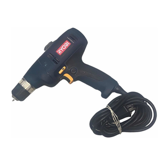
OPERATOR'S MANUAL
3/8
in. DRILL
DOUBLE INSULATED
D41
Advertisement
Table of Contents

Related Manuals for Ryobi D41


Summary of Contents for Ryobi D41
- Page 1 Your drill has been engineered and manufactured to our high standard for dependability, ease of operation, and operator safety. When properly cared for, it will give you years of rugged, trouble-free performance. WARNING: To reduce the risk of injury, the user must read and understand the operator's manual before using this product.
-
Page 2: Table Of Contents
The replacement power tool will be covered by the limited warranty for the balance of the two year period from the date of the original purchase. WHAT THIS WARRANTY COVERS: This warranty covers all defects in workmanship or materials in your RYOBI power ®... -
Page 3: General Safety Rules
WARNING! Read all instructions. Failure to follow all instructions listed below may result in electric shock, fire and/or serious injury. The term “power tool” in all of the warn- ings listed below refers to your mains-operated (corded) power tool or battery-operated (cordless) power tool. SAVE THESE INSTRUCTIONS WORK AREA SAFETY n Keep work area clean and well lit. -
Page 4: Specific Safety Rules
SERVICE n Have your power tool serviced by a qualified repair person using only identical replacement parts. This will ensure that the safety of the power tool is maintained. n When servicing a power tool, use only identical replace- ment parts. Follow instructions in the Maintenance sec- tion of this manual. -
Page 5: Symbols
Some of the following symbols may be used on this tool. Please study them and learn their meaning. Proper interpreta- tion of these symbols will allow you to operate the tool better and safer. SYMBOL NAME Volts Amperes Hertz Watt Minutes Alternating Current Direct Current... - Page 6 The following signal words and meanings are intended to explain the levels of risk associated with this product. SYMBOL SIGNAL DANGER: WARNING: CAUTION: CAUTION: SERVICE Servicing requires extreme care and knowledge and should be performed only by a qualified service technician. For service we suggest you return the product to the nearest AUTHORIZED SERVICE CENTER for repair.
-
Page 7: Electrical
DOUBLE INSULATION Double insulation is a concept in safety in electric power tools, which eliminates the need for the usual three- wire grounded power cord. All exposed metal parts are isolated from the internal metal motor components with protecting insulation. Double insulated tools do not need to be grounded. -
Page 8: Features
SWITCH TRIGGER LEVELS Levels are located on the top and end of the motor housing to help keep the drill bit level during use. LOCK-ON BUTTON The lock-on button is convenient for continuous drilling for extended periods of time. VARIABLE SPEED... -
Page 9: Assembly
Drilling in metals n Mixing paint SWITCH TRIGGER See Figure 2. To turn the drill ON, depress the switch trigger. To turn it OFF, release the switch trigger. VARIABLE SPEED The variable speed switch delivers higher speed and torque with increased trigger pressure and lower speed with de- creased trigger pressure. -
Page 10: Installing Bits
Open or close the chuck jaws to a point where the open- ing is slightly larger than the bit size you intend to use. Also, raise the front of the drill slightly to keep the bit from falling out of the chuck jaws. -
Page 11: Removing Bits
Remove the drill bit. LOCK-ON BUTTON See Figure 5. This drill is equipped with a lock-on feature, which is con- venient for continuous drilling for extended periods of time. To lock-on: n Depress the switch trigger. - Page 12 This will prevent the drill bit from slipping off-center as the hole is started. n When drilling metals, use a light oil on the drill bit to keep it from overheating. The oil will prolong the life of the bit and increase the drilling action.
-
Page 13: Maintenance
WARNING: When servicing, use only identical replacement parts. Use of any other parts may create a hazard or cause product damage. WARNING: Always wear safety goggles or safety glasses with side shields during power tool operation or when blowing dust. If operation is dusty, also wear a dust mask. GENERAL MAINTENANCE Avoid using solvents when cleaning plastic parts. -
Page 14: Chuck Removal
Unplug the drill. n Insert a 5/16 in. or larger hex key into the chuck of the drill and tighten the chuck jaws securely. n Tap sharply with a mallet in a counterclockwise direction. This will loosen the chuck on the spindle. It can now be unscrewed by hand. - Page 15 NOTES...
- Page 16 Please record the model number and serial number in the space provided below. • HOW TO ORDER REPAIR PARTS When ordering repair parts, always give the following information: • MODEL NUMBER • SERIAL NUMBER Ryobi is a registered trademark of Ryobi ® 983000-809 11-15-05 (REV:02) OPERATOR’S MANUAL in. DRILL DOUBLE INSULATED Limited used under license.