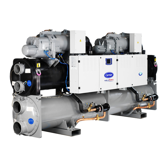
Carrier 30XW Installation, Operation And Maintenance Instructions
Water-cooled screw chillers
water-sourced screw heat pumps
nominal cooling capacity: 273-1756 kw
nominal heating capacity: 317-1989 kw
50 hz
Hide thumbs
Also See for 30XW:
- Operation instructions manual (39 pages) ,
- User manual (56 pages) ,
- Installation, operation and maintenance instructions (52 pages)
Table of Contents
Advertisement
Advertisement
Table of Contents

Related Manuals for Carrier 30XW


Summary of Contents for Carrier 30XW
- Page 1 M A I N T E N A N C E I N S T R U C T I O N S Water-Cooled Screw Chillers Water-sourced screw heat pumps 30XW/30XW-P«A» 30XWH/30XWHP«A» Nominal cooling capacity: 273-1756 kW Nominal heating capacity: 317-1989 kW...
-
Page 2: Table Of Contents
2.2 - Moving and siting the unit ............................... 9 3 - DIMENSIONS, CLEARANCES ............................10 3.1 - 30XW--/30XWH- 254-852 – 30XW-P/30XWHP 512-862 ....................10 3.2 - 30XW--/30XWH- 1002-1552 – 30XW-P/30XWHP 1012-1464 ................... 11 3.3 - 30XW--/30XWH- 1652-1702 – 30XW-P/30XWHP 1612-1762 ................... 12 4 - PHYSICAL AND ELECTRICAL DATA .......................... - Page 3 13.5 - Tightening torques for the main bolts and screws ......................32 13.6 - Evaporator and condenser maintenance ........................... 32 13.7 - Compressor maintenance ..............................32 14 - START-UP CHECKLIST FOR 30XW LIQUID CHILLERS (USE FOR JOB FILE) ..........34 This manual applies to the following four 30XW unit types: •...
-
Page 4: Introduction
Use slings or lifting beams with the correct capacity, and always follow the lifting instructions on the certified Prior to the initial start-up of the 30XW units, the people drawings supplied with the unit. Do not tilt the unit more than 15°. -
Page 5: Equipment And Components Under Pressure
1.3 - Maintenance safety considerations fluid may then be decomposed into toxic residues when subjected to the flame: Carrier recommends the following drafting for a logbook • Stay away from the unit (the table below should not be considered as reference •... - Page 6 Any intervention on the refrigerant circuit of this product should be performed in accordance with the Consult Carrier Service for this type of test. Carrier applicable legislation. In the EU, the regulation is mentions here only the principle of a test without called F-Gas, N°517/2014.
-
Page 7: Repair Safety Considerations
If the refrigerant circuit remains open for longer than a day the pressures given on the unit name plate. after an intervention (such as a component replacement), the openings must be plugged and the circuit must be Do not use air for leak testing. Use only refrigerant or dry charged with nitrogen (inertia principle). -
Page 8: Preliminary Checks
2 - PRELIMINARY CHECKS Do not attempt to remove refrigerant circuit components or fittings, while the machine is under pressure or while it 2.1 - Check equipment received is running. Be sure pressure is at 0 kPa before removing components or opening a circuit. •... -
Page 9: Moving And Siting The Unit
2.2 - Moving and siting the unit 2.2.3 - Checks before system start-up Before the start-up of the refrigeration system, the complete installation, including the refrigeration system must be 2.2.1 - Moving verified against the installation drawings, dimensional See chapter 1.1 “Installation safety considerations”. drawings, system piping and instrumentation diagrams and the wiring diagrams. -
Page 10: Dimensions, Clearances
3 - DIMENSIONS, CLEARANCES 3.1 - 30XW--/30XWH- 254-852 – 30XW-P/30XWHP 512-862 Evaporator Condenser Dimensions in mm Standard-efficiency units 30XW--/30XWH- 1567 2724 141.3 141.3 2600 1567 2724 141.3 141.3 2600 1567 2724 141.3 141.3 2600 1693 2742 141.3 141.3 2600 1693 2742 141.3... -
Page 11: 30Xw--/30Xwh- 1002-1552 - 30Xw-P/30Xwhp 1012-1464
3.2 - 30XW--/30XWH- 1002-1552 – 30XW-P/30XWHP 1012-1464 Evaporator Condenser Dimensions in mm Standard-efficiency units 30XW--/30XWH- 1002 1870 1036 4025 219.1 168.3 3800 1052 1870 1036 4025 219.1 168.3 3800 1152 1925 1036 4025 219.1 219.1 3800 1252 2051 1512 1162 4730 219.1 219.1 4500... -
Page 12: 30Xw--/30Xwh- 1652-1702 - 30Xw-P/30Xwhp 1612-1762
3.3 - 30XW--/30XWH- 1652-1702 – 30XW-P/30XWHP 1612-1762 Evaporator Dimensions in mm Standard-efficiency units 30XW--/30XWH- 1652 1515 1568 1902 4790 219.1 219.1 4500 1702 1515 1568 1902 4790 219.1 219.1 4500 High-efficiency units 30XW-P/30XWHP 1562 1591 2129 4832 273.1 273.1 4600... -
Page 13: Physical And Electrical Data
4 - PHYSICAL AND ELECTRICAL DATA 4.1 - Physical data, units without options 150, 5 and 6 Standard-efficiency units 30XW--/30XWH 1002 1052 1154 1252 1352 1452 1552 1652 1702 Sound levels - standard unit Sound power level dB(A) Sound pressure level at 1 m... -
Page 14: Electrical Data, Units Without Options 150, 5 And 6
4.2 - Electrical data, units without options 150, 5 and 6 Standard-efficiency units 30XW--/30XWH 1002 1052 1154 1252 1352 1452 1552 1652 1702 Power circuit Nom. power supply V-ph-Hz 400-3-50 Voltage range 360-440 24 V via the built-in transformer Control circuit Nominal start-up current* Circuit A Circuit B... -
Page 15: Short-Circuit Stability Current For All Units
(earthing system type): 50 kA (conditional system control box immediately downstream from the unit connec- tion point. short-circuit current Icc/Icf at the unit connection point as rms value). 4.4 - Compressor electrical data 30XW Compressor I Nom (A)* I Max (A)** I Max (A)**... -
Page 16: Electrical Connection
Electrical data notes and operating conditions, 30XW units 1. The operating environment for the 30XW units is specified below: • Environment** Environment as classified in EN 60721 (corresponds to IEC 60721): indoor installation • As standard: ambient temperature range: minimum temperature +5°C to +42°C, class 30XW 254 to 862 units have a single power connection point located immediately upstream of the main disconnect switch. altitude: lower than or equal to 2000 m 30XW 1002 to 1762 units have two connection points located immediately presence of water: class AD2 (possibility of water droplets) upstream of the main disconnect switches. presence of hard solids, class 4S2 (no significant dust present) • The control box includes the following standard features: presence of corrosive and polluting substances, class 4C2 (negligible) One main disconnect switch per circuit*... -
Page 17: Power Cable Entry
Refer to the 30XA/30XW Pro-Dialog Control manual and the certified wiring diagram supplied with the unit for the The power cables can enter the 30XW control box from field control wiring of the following features: above the unit. A removable aluminium plate on the upper •... -
Page 18: 24 And 230 V Power Reserve For The User
1 A maximum at 230 V. The connection is via a CEE7/7 type socket (2 poles with earth) located under the control box and accessible from outside. 6 - APPLICATION DATA 6.1 - Operating limits for 30XW units 30XW--/30XW-P Minimum Maximum Evaporator Entering temperature at start-up 35.0°C... -
Page 19: Standard And Optional Number Of Water Passes
6.5 - Standard and optional number of water passes Standard-efficiency units 30XW-- Size 1002 1052 1154 1252 1352 1452 1552 1652 1702 Evaporator Standard Option 100C Condenser Standard Option 102C High-efficiency units 30XW-P Size 1012 1162 1314 1464 1612 1762... -
Page 20: Evaporator Pressure Drop Curves
6.9 - Evaporator pressure drop curves Units with two evaporator passes (standard): Units with one evaporator pass (option 100C): 30XW--/30XWH-/30XW-P/30XWHP 30XW--/30XWH-/30XW-P/30XWHP 1 2 3 5 6 7 8 9/10 11 13/14 5 6 7 10/11 90 100 110 120 90 100 110 120... -
Page 21: Water Connections
Verify then, the need to install sacrificial anodes. In case additives or other fluids than those recommend- ed by Carrier are used, ensure that the fluids are not considered as a gas, and that they belong to class 2, as... -
Page 22: Water Connections
Evaporator flow switch and chilled water pump interlock The evaporator (and condenser) are of the shell and tube IMPORTANT: On 30XW units, the unit water flow switch type with removable water boxes to facilitate cleaning. must be energised. Failure to follow this instruction will Re-tightening or tightening must be done in accordance void the Carrier guarantee. -
Page 23: Operation Of Two Units In Master/Slave Mode
30XW with configuration: leaving water control 8.5 - Operating modes for Heat Machine units 8.5.1 - Cooling mode This operating mode is the same as that for 30XW units. The unit controls on the cooling setpoint. 8.5.2 - Heating mode Unlike in the cooling mode, the unit uses the heating setpoint in this configuration. -
Page 24: Option For High Condensing Temperatures (Option 150)
9 - OPTION FOR HIGH CONDENSING TEMPERATURE (OPTION 150) 9.1 - Physical data, units with option 150 Standard-efficiency units (option 150) 30XW--/30XWH 1002 1052 1154 1252 1352 1452 1552 1652 1702 Sound levels - unit with option 150 Sound power level... -
Page 25: Electrical Data, Units With Option 150
9.2 - Electrical data, units with option 150 Standard-efficiency units (option 150) 30XW--/30XWH 254 304 354 402 452 552 602 652 702 802 852 1002 1052 1154 1252 1352 1452 1552 1652 1702 Power circuit Nominal power supply V-ph-Hz 400-3-50... -
Page 26: Dimensions And Clearances, Units With Option 150
6 with three passes. weight concentration of 30%) 10.1 - Physical data, units with options 5 and 6 Standard-efficiency and high-efficiency 30XW- / 30XWH units (options 5 and 6) Option 5 (medium temperature) Option 6 (low temperature) -
Page 27: Electrical Data, Units With Options 5 And 6
10.2 - Electrical data, units with options 5 and 6 The electrical data of 30XW units with options 5 and 6 are the same as for 30XW heat units with option 150. Please refer to chapter 9.2. 10.3 - Dimensions, clearances, units with option 5... -
Page 28: Major System Components And Operation Data
11.1.2 - Refrigerant procedures and by qualified operators. The 30XW is a liquid chiller operating only with refrigerant • An indication of any modification or repair must be shown in the monitoring and maintenance file. -
Page 29: High-Pressure Safety Switch
11.4 - Electronic expansion valve (EXV) 11.2.2 - Condenser and oil separator The 30XW chiller uses a heat exchanger that is a combination condenser and oil separator. It is mounted below the The EXV is equipped with a stepper motor (2785 to 3690 evaporator. -
Page 30: Options
12 - OPTIONS Options Description Advantages Use for 30XW range Medium-temperature brine Implementation of new control algorithms and redesigned Covers specific applications such as ice storage and Only sizes solution evaporator to allow chilled brine solution production down to -6°C industrial processes 512/562/1012/1154 when ethylene glycol is used (-3°C with propylene glycol) Low-temperature brine solution Implementation of new control algorithms and redesigned Covers specific applications such as ice storage and Only sizes evaporator to allow chilled brine solution production down to -12°C industrial processes 512/562/1012/1154 when ethylene glycol is used (-8°C with propylene glycol) Light-brine solution, down to Implementation of new control algorithms and redesigned Matches with most application requirements for 254-1762 -3°C... -
Page 31: Standard Maintenance
Removal or dismantling of the HVAC unit • Check the unit alarm report when the unit does not • Any intervention due to a missed established mainte- work (see report in the 30XA/30XW Pro-Dialog Plus nance operation control manual). • Any intervention covered by the warranty •... -
Page 32: Tightening Torques For The Main Bolts And Screws
13.5 - Tightening torques for the main bolts and screws 13.4.2 - Connection precautions for the compressor power terminals These precautions must be applied during an intervention Screw type Used for Torque value, N·m that requires the removal of the power conductors connected M20 nut Chassis to the compressor supply terminals. - Page 33 The switch that has been selected for detecting reverse rotation is Carrier part number HK01CB001. This switch opens the contacts when the pressure falls below 7 kPa. The switch is a manual reset type that can be reset after the pressure has once again risen above 70 kPa.
-
Page 34: Start-Up Checklist For 30Xw Liquid Chillers (Use For Job File)
14 - START-UP CHECKLIST FOR 30XW LIQUID CHILLERS (USE FOR JOB FILE) Preliminary information Job name: ....................................... Location: ........................................ Installing contractor:..................................... Distributor: ......................................Unit Model: .................... Compressors Circuit A Circuit B Model number ................Model number ................Serial number ................Serial number ................ - Page 35 WARNING: Operation of the chiller with an improper supply voltage or excessive phase imbalance constitutes abuse which will invalidate the Carrier warranty. If the phase imbalance exceeds 2% for voltage, or 10% for current, contact your local electricity supplier at once and ensure that the chiller is not switched on until corrective measures have been taken.
- Page 36 Order No: 13458, 01.2018 - Supersedes order No: 13458, 03.2017. Manufacturer: Carrier SCS, Montluel, France. Manufacturer reserves the right to change any product specifications without notice. Printed in the European Union.