Carrier AQUASNAP 30RQ Installation, Operation And Maintenance Instructions
Hide thumbs
Also See for AQUASNAP 30RQ:
- Operation and maintenance instructions (36 pages) ,
- Installation, operation and maintenance instructions (104 pages) ,
- Manual (15 pages)
Table of Contents
Advertisement
Quick Links
Библиотека СОК
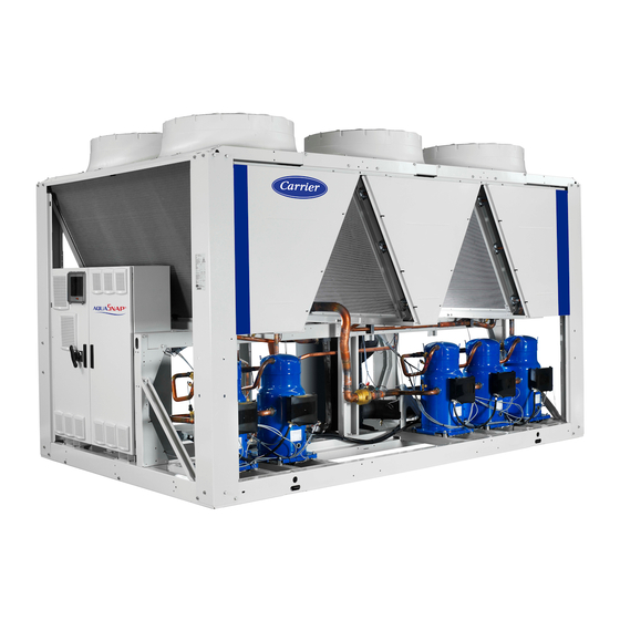
30RQ 262-522
Reversible Air-to-Water
Heat Pumps with Integrated
Hydronic Module
Nominal cooling capacity 240-465 kW
Nominal heating capacity 270-560 kW
50 Hz
Unit with Euro Pack option shown
Installation, operation and maintenance instructions
Carrier participe au programme
Carrier is participating in the
de certification EUROVENT.
Eurovent Certification Programme.
Les produits figurent dans
Products are as listed in the
l'Annuaire EUROVENT des
Eurovent Directory of Certified
produits certifiés.
Products.
Advertisement
Table of Contents

Related Manuals for Carrier AQUASNAP 30RQ


Summary of Contents for Carrier AQUASNAP 30RQ
- Page 1 Hydronic Module Nominal cooling capacity 240-465 kW Nominal heating capacity 270-560 kW 50 Hz Carrier participe au programme Carrier is participating in the de certification EUROVENT. Eurovent Certification Programme. Les produits figurent dans Products are as listed in the l'Annuaire EUROVENT des Eurovent Directory of Certified produits certifiés.
-
Page 2: Table Of Contents
Contents 1 - INTRODUCTION ..................................4 1.1 - Check equipment received ................................4 1.2 - Installation safety considerations ..............................4 1.3 - Equipment and components under pressure ..........................4 1.4 - Maintenance safety considerations .............................5 2 - MOvINg aND sITINg The UNIT ............................6 2.1 - Moving ....................................... - Page 3 12.6 - Air heat exchanger ................................. .35 12.7 - Water heat exchanger maintenance ............................35 12.8 - Characteristics of R-410A ..............................35 13 - lIsT OF CheCKs TO Be CaRRIeD OUT By The INsTalleR BeFORe CallINg CaRRIeR seRvICe FOR UNIT MaINTeNaNCe ................................. 36...
-
Page 4: Introduction
If necessary, the damaged parts must be These products incorporate equipment or components under repaired or replaced. See also chapter “Maintenance”. pressure, manufactured by Carrier or other manufacturers. We recommend that you consult your appropriate national trade 1.2 - Installation safety considerations association or the owner of the equipment or components under pressure (declaration, re-qualification, retesting, etc.). -
Page 5: Maintenance Safety Considerations
1.4 - Maintenance safety considerations Check manual “30RB/RQ Pro-Dialog Plus control” for a detailed explanation of the high-pressure switch test method. Engineers working on the electric or refrigeration components At least once a year thoroughly inspect the protection devices must be authorized, trained and fully qualified to do so. (valves). -
Page 6: Moving And Siting The Unit
2 - MOvINg aND sITINg ThE UNIT Never apply an open flame or live steam to a refrigerant container. Dangerous overpressure can result. 2.1 - Moving During refrigerant removal and storage operations follow applicable regulations. These regulations, permitting condition- See chapter “Installation safety considerations”. ing and recovery of halogenated hydrocarbons under optimum 2.2 - siting the unit quality conditions for the products and optimum safety... -
Page 7: Checks Before System Start-Up
2.3 - Checks before system start-up Before the start-up of the refrigeration system, the complete installation, including the refrigeration system must be verified against the installation drawings, dimensional drawings, system piping and instrumentation diagrams and the wiring diagrams. During the installation test national regulations must be followed. -
Page 8: Dimensions, Clearances
3 - DIMENsIONs, ClEaRaNCEs For desuperheater heat reclaim option see chapter 11. 3.1 - 30RQ 262 2410 2457 Power connection With hydronic module 1500 1500 For user control connection legend: Without hydronic module Clearances required for maintenance and air flow 1500 Clearances recommended for heat exchanger tube removal... -
Page 9: 30Rq 302-522
3.2 - 30RQ 302-522 30RQ 302-402 3604 432-522 4798 Power connection With hydronic module 1500 1500 For user control connection Without hydronic module 1500 1500 legend: NOTE: Non-contractual drawings. Water inlet Clearances required for maintenance and air flow When designing an installation, refer to the certified dimensional drawings, available on request. -
Page 10: Multiple Heat Pump Installation
3.3 - Multiple heat pump installation NOTE: If the walls are higher than 2 m, contact the factory 1500 1500 In case of multiple heat pumps (up to four units), the respective clearance between them should be increased from 1500 to 3000 mm for the side space requirement. -
Page 11: Electrical Data - 30Rq
5 - ElECTRICal DaTa - 30RQ 30RQ Power circuit Nominal power supply V-ph-Hz 400-3-50 Voltage range 360-440 Control circuit supply 24 V, via internal transformer Nominal unit current draw* Circuit A + B (one power supply) Maximum unit power input** Circuit A + B (one power supply) Unit power factor at max. -
Page 12: Electrical Data, Hydronic Module
5.2 - Electrical data, hydronic module 30RQ single and dual low-pressure pump Shaft power Power input* Nominal current draw 10.3 10.3 Maximum current draw at 400 V** 11.2 11.2 single and dual high-pressure pump Shaft power Power input* 12.2 12.2 Nominal current draw 10.3 10.3... -
Page 13: Application Data
Notes: Do not exceed the maximum operating temperature. For applications requiring a temperature below 6.8°C, please contact Carrier. For operation down to -20°C the unit must be equipped with option 28 (winter operation). In addition the unit must either be equipped with the frost protec-tion option or the water loop must be protected by the installer by adding a frost protection solution. -
Page 14: Variable Flow Water Heat Exchanger
6.4 - variable flow water heat exchanger 6.6 - Maximum system water volume Variable water heat exchanger flow can be used in standard Units with hydronic module incorporate an expansion tank that heat pumps. The flow rate must be higher than the minimum limits the water volume. -
Page 15: Electrical Connection
IT type divider for • Electrical reserves: the system units that require this and/or a TN type divider for Carrier units. Circuit A has disconnect switches and branch sections, designed to supply Please consult the appropriate local organisations to define the monitoring and protection elements and to complete the electrical installation. -
Page 16: Recommended Wire Sections
The accessory connection extension box site. The following is only to be used as a guideline, and does not make Carrier in any way liable. After wire sizing has been ensures mechanical protection of the stripped cable, before it enters the control box. -
Page 17: Water Connections
• In case additives or other fluids than those recommended by Carrier are used, ensure that the fluids are not considered water circuit by the installer. Never use the unit heat exchangers to add heat exchange fluid. -
Page 18: Hydronic Connections
8.2 - hydronic connections 8.2.1 - Unit equipped with hydronic module option This diagram illustrates a typical hydronic installation. legend Installation components Components of the unit and hydronic module 18 Air vent Victaulic screen filter 19 Flexible connection Expansion tank 20 Check valve Safety valve 21 Charge valve... -
Page 19: Flow Control
8.2.2 - Unit without hydronic module option Typical water circuit diagram - without hydronic module legend Control valve Air vent Flow switch for the water heat exchanger (supplied) Flexible connection Heat exchanger Temperature sensor (supplied) Drain Buffer tank (if needed) Filter (mesh size: 1.2 mm = 20 mesh) 10 Expansion tank 11 Fill valve... -
Page 20: Supplementary Electric Resistance Heaters
30RQ with configuration: leaving water control Typical accessory installation diagram legend Master unit Slave unit Control boxes of the master and slave units legend Electric heater power supply 400 V-3 ph-50 Hz Water inlet Accessory control board for four additional electric heaters Water outlet Internal communication bus Heater stage control contactors... - Page 21 Example of additional electric heaters Outdoor air temperature, °C legend Stage 1 Stage 2 Stage 3 Stage 4 Heat pump capacity variation as a function of the air temperature Building thermal load Balance point between the capacity supplied by the heat pump and the thermal load of the building Operating range, in which the heat pump capacity is lower than the building thermal load Operating range, in which the heat pump capacity is higher than the building thermal load...
-
Page 22: Nominal System Water Flow Control
9 - NOMINal sYsTEM WaTER FlOW CONTROl If the pressure drop has increased, this indicates that the screen filter must be removed and cleaned, as the hydronic circuit The water circulation pumps of the 30RQ units have been sized contains solid particles. In this case close the shutoff valves at the water inlet and outlet and remove the screen filter after to allow the hydronic modules to cover all possible configura- emptying the hydronic section of the unit. -
Page 23: Pump Pressure/Flow Rate Curves
9.2 - Pump pressure/flow rate curves low-pressure pumps Water flow rate, l/s legend 30RQ 262 30RQ 302-342 30RQ 372-402-432 30RQ 462-522 high-pressure pumps Water flow rate, l/s legend 30RQ 262 30RQ 302-342 30RQ 372-402-432 30RQ 462-522... -
Page 24: Available Static System Pressure
9.3 - available static system pressure low-pressure pumps Water flow rate, l/s legend 30RQ 262 30RQ 302 30RQ 342 30RQ 372 30RQ 402-432 30RQ 462-522 high-pressure pumps Water flow rate, l/s legend 30RQ 262 30RQ 302 30RQ 342 30RQ 372 30RQ 402-432 30RQ 462-522... -
Page 25: Major System Components
Each motor to which they are applied. This is also the case for the products is fixed with transverse supports. The motors are three-phase, originally supplied by Carrier. with permanently lubricated bearings and insulation class F. -
Page 26: Refrigerant
NOTES: Monitoring during operation, re-qualification, re- Recycling testing and re-testing dispensation: The unit is wholly or partly recyclable. After use it contains Follow the regulations on monitoring pressurised refrigerant vapours and oil residue. It is coated by paint. equipment. It is normally required that the user or operator sets up Operating life and maintains a monitoring and maintenance file. -
Page 27: Options And Accessoires
11 - OPTIONs aND aCCEssOIREs 11.1 - heat reclaim option using desuperheaters This option permits the production of free hot water using heat reclaim by desuperheating the compressor discharge gases. The option is available for the whole 30RQ range. A plate heat exchanger is installed in series with the air condenser coils on the compresseur discharge line of each circuit. - Page 28 11.1.2 - Dimensional drawings for units equipped with the desuperheater option 30RQ 262 2410 2457 Power connection Unit with hydronic module ∅ 2" Cylindrical gas thread, desuperheater-side 1500 legend: all dimensions are in mm. Clearances required for maintenance and air flow Clearances recommended for evaporator tube removal...
- Page 29 30RQ 302-522 Power connection Unit with hydronic module 1500 ∅ 2" Cylindrical gas thread, desuperheater-side 1500 Control power user connection Unit without hydronic module 1500 Cylindrical gas thread, desuperheater-side ∅ 2" 1500 legend: Clearances required for maintenance and air flow 30RQ Clearances recommended for evaporator tube removal 302-402...
- Page 30 11.1.3 - Installation and operation of the heat reclaim with During the unit installation the heat reclaim plate heat desuperheater option exchangers must be insulated and frost protected, if required. The 30RQ units with the desuperheater option (No. 49) are Please refer to the typical installation diagram below for the supplied with one heat exchanger per refrigerant circuit.
- Page 31 Entering air temperature °C Available static pressure Note: Do not exceed the maximum operating temperature. For an application that requires operation below 6.8°C, contact Carrier. 0.28 (1) 2.78 (10) 8.33 (30) The entering water temperature at start-up must not be lower than 25°C. For installations with a lower temperature a three-way valve is necessary.
-
Page 32: Option 241
11.1.6 - Control configuration with the desuperheater option 11.2 - Option 241 This configuration allows the user to enter a setpoint that is During transport in a closed container the refrigerant charge relative to the minimum condensing temperature (default = must be transferred to the air heat exchanger. -
Page 33: Other Options And Accessories
11.3 - Other options and accessories Options Description advantages Condenser with pre-treated Pre-treated aluminium fins (polyurethane and epoxy) Improved corrosion resistance, recommended for 30RQ 262-522 fins* marine environments Low noise level Sound absorbing compressor enclosure Noise emission reduction 30RQ 262-522 IP54 protection Increased leak tightness of control boxes Recommended for dusty operating environments... -
Page 34: Standard Maintenance
HVAC unit nul and void, and the manufacturer, General visual inspection for any signs of deterioration. Carrier France, will no longer be held responsible. 12.4 - Tightening torques for the main electrical 12.2 - level 2 maintenance (see note) -
Page 35: Air Heat Exchanger
12.6 - air heat exchanger Correct and frequent cleaning (approximately every three months) will prevent 2/3 of the corrosion problems. We recommend, that finned coils are inspected regularly to Protect the control box during cleaning operations. check the degree of fouling. This depends on the environment where the unit is installed, and will be worse in urban and 12.7 - Water heat exchanger maintenance industrial installations and near trees that shed their leaves. -
Page 36: List Of Checks To Be Carried Out By The Installer Before Calling Carrier Service For Unit Maintenance
13 - lIsT OF ChECKs TO BE CaRRIED OUT BY ThE INsTallER BEFORE CallINg CaRRIER sERvICE FOR UNIT MaINTENaNCE Is there any shipping damage? ............ If so, where? ..........................................................Will this damage prevent unit start-up? ............................. Unit is level in its installation...