Table of Contents
Advertisement
I N S T A L L A T I O N ,
O P E R A T I O N
A N D
Touch Pilot Junior
M A I N T E N A N C E
I N S T R U C T I O N S
30RQSY
30RQS
For the operation of the control please refer to the
Touch Pilot Junior Control manual for the 30RB/30RQ 017-160 series
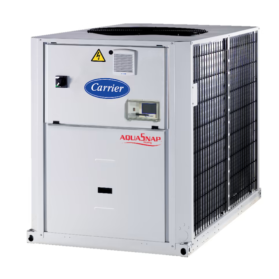
Reversible Air-to-Water Heat Pumps
30RQS/30RQSY 039-160 "A"
Nominal cooling capacity 40-160 kW
50 Hz
Original instructions
Advertisement
Table of Contents

Related Manuals for Carrier Aquasnap 30RQS Series


Summary of Contents for Carrier Aquasnap 30RQS Series
- Page 1 I N S T A L L A T I O N , O P E R A T I O N A N D Touch Pilot Junior M A I N T E N A N C E I N S T R U C T I O N S 30RQSY 30RQS For the operation of the control please refer to the...
-
Page 2: Table Of Contents
CONTENTS 1 - INTRODUCTION ..................................4 1.1 - Specific aspects for 30RQSY units with variable available pressure ................... 4 1.2 - Check equipment received ..............................4 1.3 - Installation safety considerations ............................4 1.4 - Equipment and components under pressure ........................6 1.5 - Maintenance safety considerations ............................ - Page 3 12 - WATER CONNECTIONS ..............................32 12.1 - Operating precautions and recommendations ........................32 12.2 - Hydronic connections ................................33 12.3 - Frost protection ..................................33 12.4 - Protection against cavitation (option 116) ........................33 13 - NOMINAL SYSTEM WATER FLOW CONTROL ......................36 13.1 - Units without hydronic module ............................
-
Page 4: Introduction
1 - INTRODUCTION and pressure drops of the system ductwork. Prior to the initial start-up of the 30RQS/30RQSY units, the In the heating mode, the full-load or part-load speed of each people involved should be thoroughly familiar with these circuit is fixed and at the configured maximum (range instructions and the specific project data for the installation site. - Page 5 Do not remove the skid or the packaging until the unit is DO NOT COVER ANY PROTECTION DEVICES. in its final position. These units can be moved with a fork lift truck, as long as the forks are positioned in the right This applies to fuse plugs and relief valves (if used) in the place and direction on the unit.
-
Page 6: Equipment And Components Under Pressure
The presence of oil at the outlet orifice is a useful indicator that refrigerant has Carrier recommends the following drafting for a logbook (the leaked. Keep this orifice clean to ensure that any leaks are... -
Page 7: Repair Safety Considerations
Recommissioning of the equipment. or gases containing oxygen can be the cause of an explosion. Consult Carrier Service for this type of test. Carrier mentions Oxygen reacts violently with oil and grease. here only the principle of a test without removing the pressure... -
Page 8: Moving And Siting The Unit
Never exceed the specified maximum operating pressures. Verify Do not step on refrigerant lines. The lines can break under the the allowable maximum high- and low-side test pressures by weight and release refrigerant, causing personal injury. checking the instructions in this manual and the pressures given on the unit name plate. -
Page 9: Checks Before System Start-Up
• Check that all protection documents and equipment Typical applications of these units do not require earthquake resistance. Earthquake resistance has not been verified. provided by the manufacturer (dimensional drawings, P&ID, declarations etc.) to comply with the regulations are present. CAUTION: Only use slings at the designated lifting points •... -
Page 10: Duct Connection
3.2 - Duct connection Specific connection precautions for sizes 30RQSY 050 to 078 30RQSY units can be installed inside a building and connected to a air distribution duct network: Air heat exchanger side, at the fresh air suction side for 30RQSY 039 to 078 units Air inlet Fan discharge side at the evacuation side of the treated... -
Page 11: Electrical Protection Of The Fan Motors
Ref.: 30RY 900 032 EE – (30RQSY 039 to 078) IMPORTANT: The connection of the ducts to the units must It may be necessary to remove water. Carrier can supply an not lead to a mechanical constraint on the decks supporting accessory condensate collection pan for installation under the fans. -
Page 12: Dimensions, Clearances
4 - DIMENSIONS, CLEARANCES 4.1 - 30RQS 039 and 045-078, units with and without hydronic module For units with fans with variable available pressure (30RQSY) please refer to the pages that follow. 2050 1000 1000 NOTES: Legend: Non-certified drawings. All dimensions are given in mm Refer to the certified dimensional drawings supplied with the unit or available on request, when designing an installation. -
Page 13: 30Rqs 080-160, Units With And Without Hydronic Module
4.2 - 30RQS 080-160, units with and without hydronic module For units with fans with variable available pressure (30RQSY) please refer to the pages that follow. 2136 1000 1000 Legend: NOTES: Non-certified drawings. All dimensions are given in mm Refer to the certified dimensional drawings supplied with the unit or available on Control box request, when designing an installation. -
Page 14: 30Rqsy 039-045, Units With And Without Hydronic Module, Without Filter Frame
4.3 - 30RQSY 039-045, units with and without hydronic module, without filter frame Legend: NOTES: Non-certified drawings. All dimensions are given in mm Refer to the certified dimensional drawings supplied with the unit or available on Control box request, when designing an installation. For the location of fixing points, weight distribution and coordinates of the centre of gravity refer to the certified dimensional drawings. Water inlet Provide a gutter around the unit to collect the condensate water or install the accessory condensate collection pan (30RQSY 039 to 078). -
Page 15: 30Rqsy 039-045, Option 23B, Units With And Without Hydronic Module, With Filter Frame
4.4 - 30RQSY 039-045, option 23B, units with and without hydronic module, with filter frame Legend: NOTES: Non-certified drawings. All dimensions are given in mm Refer to the certified dimensional drawings supplied with the unit or available Control box on request, when designing an installation. For the location of fixing points, weight distribution and coordinates of the centre of gravity refer to the certified dimensional drawings. Water inlet Provide a gutter around the unit to collect the condensate water or install the accessory condensate collection pan (30RQSY 039 to 078). -
Page 16: 30Rqsy 050-078, Units With And Without Hydronic Module, Without Filter Frame
4.5 - 30RQSY 050-078, units with and without hydronic module, without filter frame Legend: NOTES: Non-certified drawings. All dimensions are given in mm Refer to the certified dimensional drawings supplied with the unit or available on Control box request, when designing an installation. For the location of fixing points, weight distribution and coordinates of the centre of gravity refer to the certified dimensional drawings. Water inlet Provide a gutter around the unit to collect the condensate water or install the accessory condensate collection pan (30RQSY 039 to 078). -
Page 17: 30Rqsy 050-078 Option 23B, Units With And Without Hydronic Module, With Filter Frame
4.6 - 30RQSY 050-078 option 23B, units with and without hydronic module, with filter frame Legend: All dimensions are given in mm Control box Water inlet Water outlet Required clearances for air flow Recommended clearances for maintenance Air outlet, do not obstruct Power cable entry NOTES: Non-certified drawings. Refer to the certified dimensional drawings supplied with the unit or available on request, when designing an installation. For the location of fixing points, weight distribution and coordinates of the centre of gravity refer to the certified dimensional drawings. Provide a gutter around the unit to collect the condensate water or install the accessory condensate collection pan (30RQSY 039 to 080). -
Page 18: 30Rqsy 080-120 Units With And Without Hydronic Module
4.7 - 30RQSY 080-120 units with and without hydronic module 2050 2273 2258 Legend: 1000 All dimensions are given in mm Control box Water inlet Water outlet Required clearances for air flow Recommended clearances for maintenance Air outlet, do not obstruct Power cable entry NOTES: Non-certified drawings. Refer to the certified dimensional drawings supplied with the unit or available on request, when designing an installation. For the location of fixing points, weight distribution and coordinates of the centre of gravity refer to the certified dimensional drawings. The unit must be installed level (less than 2 mm per metre deviation in both axes). * Overall dimensions... -
Page 19: 30Rqsy 140-160 Units With And Without Hydronic Module
4.8 - 30RQSY 140-160 units with and without hydronic module 2122 2050 2273 2258 1000 Legend: All dimensions are given in mm Control box Water inlet Water outlet Required clearances for air flow Recommended clearances for maintenance Air outlet, do not obstruct Power cable entry NOTES: Non-certified drawings. Refer to the certified dimensional drawings supplied with the unit or available on request, when designing an installation. For the location of fixing points, weight distribution and coordinates of the centre of gravity refer to the certified dimensional drawings. The unit must be installed level (less than 2 mm per metre deviation in both axes). -
Page 20: 30Rqs/Rqsy 039-078 Units With Buffer Tank Module
4.9 - 30RQS/RQSY 039-078 units with buffer tank module Legend: NOTES: Non-certified drawings. All dimensions are given in mm Refer to the certified dimensional drawings supplied with the unit or available on Control box request, when designing an installation. For the location of fixing points, weight distribution and coordinates of the centre of gravity refer to the certified dimensional drawings. Water inlet The unit must be installed level (less than 2 mm per metre deviation in both axes). Water outlet Required clearances for air flow Overall dimensions RQSY *** RQSY 050-060-070-078 Recommended clearances for maintenance Air outlet, do not obstruct Power cable entry... -
Page 21: 30Rqs/Rqsy 080-160 Units With Buffer Tank Module
4.10 - 30RQS/RQSY 080-160 units with buffer tank module Legend: NOTES: Non-certified drawings. All dimensions are given in mm Refer to the certified dimensional drawings supplied with the unit or available on Control box request, when designing an installation. For the location of fixing points, weight distribution and coordinates of the centre of gravity refer to the certified dimensional drawings. Water inlet The unit must be installed level (less than 2 mm per metre deviation in both axes). Water outlet Required clearances for air flow Overall dimensions RQSY Recommended clearances for maintenance Air outlet, do not obstruct Power cable entry... -
Page 22: 30Qbs/Rqsy 039-080 Units With Desuperheater
4.11 - 30QBS/RQSY 039-080 units with desuperheater Position of the desuperheater inlets and outlets 4.12 - 30RQS/RQSY 090-120 units with desuperheater Position of the desuperheater inlets and outlets 4.13 - 30RQS/RQSY 140-160 units with desuperheater Position of the desuperheater inlets and outlets Unit water inlet and outlet Water inlet and outlet, unit with option 49... -
Page 23: Physical Data, 30Rqs Units
5 - PHYSICAL DATA, 30RQS UNITS For units with fans with variable available pressure (30RQSY 039-160) please refer to chapter 7. 30RQS Sound levels Standard unit Sound power level dB(A) Sound pressure level at 10 m dB(A) Standard unit + option 15LS Sound power level dB(A) dB(A) -
Page 24: Electrical Data, 30Rqs Units
6 - ELECTRICAL DATA, 30RQS UNITS For units with fans with variable available pressure (30RQSY 039-160) please refer to chapter 8. 30RQS - standard unit (without hydronic module) Power circuit Nominal power supply V-ph-Hz 400-3-50 Voltage range 360-440 Control circuit supply 24 V, via internal transformer Maximum start-up current (Un)* Standard unit... -
Page 25: Physical Data, 30Rqsy Units
7 - PHYSICAL DATA, 30RQSY UNITS 30RQSY Sound levels Standard unit - for 160 Pa external static pressure Sound power level at discharge dB(A) Sound pressure level radiated dB(A) Sound pressure level at 10 m dB(A) Dimensions If two values are shown the first one is for standard units and the second one for units with option 23B Length 2142/ 2142/ 2142/ 2142/... -
Page 26: Electrical Data, 30Rqsy Units
8 - ELECTRICAL DATA, 30RQSY UNITS 30RQSY - standard unit (without hydronic module) Power circuit Nominal power supply V-ph-Hz 400-3-50 Voltage range 360-440 Control circuit supply 24 V, via internal transformer Maximum start-up current (Un)* Standard unit Unit with electronic starter option Unit power factor at maximum capacity** 0.83 0.81 0.81... -
Page 27: Electrical Data, 30Rqs And 30Rqsy Units
30670 31671 31671 Earthing system type ** If another current limitation protection system is used, its time-current and thermal constraint (I²t) trip characteristics must be at least equivalent to those of the recommended Schneider circuit breaker. Contact your nearest Carrier office. The short-circuit stability current values above are in accordance with the TN system. 9.2 - Electrical data, hydronic module The pumps that are factory-installed in these units comply with the European Ecodesign directive ErP. The additional electrical data required* is as follows: Motors of single and dual low-pressure pumps (options 116T, 116U) No.** Description***... -
Page 28: Compressor Usage And Electrical Data For Standard Units
Disassembly using standard tools. Disposal and recycling using an appropriate company. Operating conditions for which the motor is specifically designed I - Altitudes above sea level < 1000†† II - Ambient air temperature °C < 55 IV - Maximum air temperature Please refer to the operating conditions given in this manual or in the specific °C conditions in the Carrier selection programs. V - Potentially explosive atmospheres Non-ATEX environment Required by regulation 640/2009 with regard to the application of directive 2009/125/EC on the eco-design requirements for electric motors ** Item number imposed by regulation 640/2009, annex I2b. *** Description given by regulation 640/2009, annex I2b. **** To obtain the maximum power input for a unit with hydronic module add the maximum unit power input from the electrical data table to the pump power input. † To obtain the maximum unit operating current draw for a unit with hydronic module add the maximum unit current draw from the electrical data table to the pump current draw. †† Above 1000 m, a degradation of 3% for each 500 m should be taken into consideration. 9.3 - Compressor usage and electrical data for standard units... -
Page 29: Application Data
Caution: If particular aspects of an actual installation do not conform to the the requirements of the installation directives. Conformance with EN 60204-1 is conditions described above, or if there are other conditions which should be the best means of ensuring compliance with the Machines Directive § 1.5.1. considered, always contact your local Carrier representative. • Annex B of EN 60204-1 describes the electrical characteristics used for the operation of the machines. -
Page 30: Water Heat Exchanger Water Flow Rate
(See note) supply voltage or excessive phase imbalance constitutes For sizes 039 to 120, N can be increased up to 4 depending on the size of the hot-water loop to prevent a water temperature drop during the defrost cycle. abuse which will invalidate the Carrier warranty. If the phase imbalance exceeds 2% for voltage, or 10% for current, NOTE: For industrial process cooling applications, where high stability of the water temperature levels must be achieved, the values above must be increased. contact your local electricity supply at once and ensure that... -
Page 31: Recommended Wire Sections
In case of accidental disconnection, conductor fixing installation site. The following is only to be used as a guide- line, and does not make Carrier in any way liable. After wire between different conductors and/or in the control box sizing has been completed, using the certified dimen-sional... -
Page 32: Water Connections
• Use a pressure reducer to maintain pressure in the Carrier are used, ensure that the fluids are not considered as circuit(s) and install a safety valve as well as an expansion a gas, and that they belong to class 2, as defined in directive tank. -
Page 33: Hydronic Connections
The hydronic circuit diagram shows a typical hydronic with nitrogen for a period of one month. If the heat transfer fluid does not comply with the Carrier regu- installation. When charging the water circuit use air vents to evacuate any residual air pockets. - Page 34 Typical hydronic circuit diagram with hydronic module Option Option Option Typical hydronic circuit diagram without hydronic module Typical hydronic circuit diagram without hydronic module Legend Components of the unit and hydronic module Installation components Screen filter (Mesh1.2 mm) 16 Thermowell Expansion tank (option) 17 Air purge 18 Flexible connexion Discharge valve...
- Page 35 Hydronic module - sizes 039-078 Hydronic module - sizes 080-160 Dual pump shown Dual pump shown Hydronic module - sizes 039-080 Hydronic module - sizes 090-160 Dual pump and buffer tank shown Dual pump and buffer tank shown...
-
Page 36: Nominal System Water Flow Control
13 - NOMINAL SYSTEM WATER FLOW CONTROL contaminating solids). • Perform another reading. • Compare this value to the initial value. A decrease in Refer to the chapter ‘‘Water connections’’ for all references the pressure drop value indicates that the filters in the points mentioned in this chapter. -
Page 37: Units With Hydronic Module And Variable-Speed Pump - Pressure Differential Control
Shut-off valves on the water inlet and outlet (item 19) and remove the filters (items 20 and 1) after See with Carrier Service to implement the procedures draining the hydronic part of the unit (item 6). described below. -
Page 38: Units With Hydronic Module And Variable-Speed Pump - Temperature Difference Control
T value than the set point. NOTES: If during controlling, the low or high frequency limits are reached See with Carrier Service to implement the procedures described below. before reaching the specified flow, keep the pressure differential value to its lower or higher limit to enter in the control 13.4.1 - Procedure for cleaning the hydronic circuit... -
Page 39: Plate Heat Exchanger Pressure Drop (Including Internal Piping) - Units Without Hydronic Module
13.5 - Plate heat exchanger pressure drop (including internal piping) - units without hydronic module 30RQS/RQSY 039-078 30RQS/RQSY 080-160 Water flow rate, l/s Water flow rate, l/s Legend Legend 1. 30RQS/30RQSY 039 1. 30RQS/30RQSY 080 2. 30RQS/30RQSY 090 2. 30RQS/30RQSY 045 3. 30RQS/30RQSY 100 3. 30RQS/30RQSY 050 4. 30RQS/30RQSY 120 4. 30RQS/30RQSY 060 5. 30RQS/30RQSY 140 5. 30RQS/30RQSY 070 6. 30RQS/30RQSY 078 6. 30RQS/30RQSY 160... -
Page 40: Available External Static Pressure - Units With Hydronic Module (Fixed-Speed Or Variable-Speed Pump, 50 Hz)
13.7 - Available external static pressure - units with hydronic module (fixed-speed or variable-speed pump, 50 Hz) Data applicable for: - Fresh water 20 °C - In case of use of the glycol, the maximum water flow is reduced. Warning : With the buffer tank module option, the curves below do not take the pressure drops for this component into account. If necessary, refer to the buffer tank characteristic curves to correct the data below. -
Page 41: Start-Up
14 - START-UP Standard configuration: return water control 14.1 - Preliminary checks Never be tempted to start the heat pump without reading fully, and understanding, the operating instructions and without having carried out the following pre-start checks: Check the chilled water circulation pumps, air handling •... -
Page 42: Supplementary Electric Resistance Heaters
14.4 - Supplementary electric resistance heaters Typical accessory installation diagram To permit staging of the capacity reduction of the heat pump at low ambient temperatures, as shown in the diagram below, it is possible to install supplementary electric heaters in the leaving water line. -
Page 43: Major System Components
15 - MAJOR SYSTEM COMPONENTS 15.4 - Fans 15.1 - Compressors The fans are axial Flying Bird fans equipped with rotating shroud and made of composite recyclable material. The 30RQS/RQSY units use hermetic scroll compressors. Each motors are three-phase, with permanently lubricated bearings compressor is equipped with a crankcase oil heater, as and insulation class F. -
Page 44: Water Evaporator/Condenser
15.11 - Storage tank coatings to which they are applied. This is also the case for the products originally supplied by Carrier SCS. 30RQS/RQSY units are equipped with mechanically welded NOTES - Monitoring during operation: storage tanks that permit storing the excess charge when the •... -
Page 45: Options
16 - OPTIONS Options Description Advantages Improved corrosion resistance, recommended for moderate marine Corrosion protection, traditional coils Fins made of pre-treated aluminium (polyurethane and 30RQS/RQSY and urban environments 039-160 epoxy) Medium-temperature brine solution Covers specific applications such as ice storage and industrial Low temperature chilled water production down to 0°C 30RQS/RQSY with ethylene glycol and propylene glycol. 039-160 processes Low-temperature brine solution Covers specific applications such as ice storage and industrial Low temperature chilled water production down to 30RQS/RQSY 039-160 -15°C with ethylene glycol and -12°C with propylene... -
Page 46: Specific Details For Units With A Fan With Available Static Pressure (30Rqsy)
17 - SPECIFIC DETAILS FOR UNITS WITH A FAN Heating mode WITH AVAILABLE STATIC PRESSURE (30RQSY) 30RQSY 039-050/30RQSY 080-120 Selection based on the pressure drop Duct pressure Fan speed, r/s Power input Heating capacity drop coefficient coefficient 18.36 0.990 1.016 The cooling and heating capacities are given for an available 18.36 0.990... -
Page 47: Installation And Operation Of The Heat Reclaim With Desuperheater Option
18.2 - Installation and operation of the heat reclaim During the unit installation the heat reclaim plate heat with desuperheater option exchangers must be insulated and frost protected, if required. The 30RQS/RQBSY units with the desuperheater option are Please refer to the typical installation diagram below for the supplied with one heat exchanger per refrigerant circuit. -
Page 48: Installation
18.3 - Installation 18.5 - Operating limits Desuperheater Minimum Maximum The water connections on the desuperheater water inlets and Entering water temperature at start-up °C outlets must not cause any mechanical local constraint at the Leaving water temperature during operation °C heat exchangers. -
Page 49: Standard Maintenance
For information: The protection values given by our supplier, install shut-off valves upstream and downstream of the unit. based on the antifreeze solutions used in the Carrier Montluel 20 - STANDARD MAINTENANCE laboratory, are as follows: (these values can change for different suppliers). -
Page 50: Level 2 Maintenance
NOTE: Any deviation or non-observation of these maintenance criteria will render the guarantee conditions for the HVAC unit nul and void, and the manufacturer, Carrier SCS, will no longer be held responsible. -
Page 51: Tightening Torques For The Main Electrical Connections
20.4 - Tightening torques for the main electrical WARNING: Never use pressurised water without a large connections diffuser. Do not use high-pressure cleaners for Cu/Cu and Cu/Al coils. Component/screw type Designation in Value (N·m) the unit Concentrated and/or rotating water jets are strictly Soldered screw (PE) customer connection forbidden. -
Page 52: Refrigerant Volume
20.8 - Refrigerant volume The unit must be operated in cooling mode to find out, if the unit charge is correct, by checking the actual subcooling. Following a small refrigerant leak a loss of refrigerant, compared to the initial charge will be noticeable in the cooling mode and affect the subcooling value obtained at the air heat exchanger (condenser) outlet, but it will not be noticeable in the heating mode. -
Page 53: Start-Up Checklist For 30Rqs/30Rqsy Heat Pumps (Use For Job File)
21 - START-UP CHECKLIST FOR 30RQS/30RQSY HEAT PUMPS (USE FOR JOB FILE) Preliminary information Job name: ....................................... Location: ........................................ Installing contractor:..................................... Distributor: ......................................Start-up preformed by: .............. Date: ....................Equipment Model 30RQS/RQSY: ..............S/N ....................Compressors Circuit A Circuit B 1. - Page 54 Check water heat exchanger water loop Water loop volume = ....(litres) Calculated volume = ....(litres) 3.25 litres/nominal kW capacity for air conditioning 6.5 litres/nominal kW capacity for process cooling Proper loop volume established Proper loop corrosion inhibitor included ..litres of ......Proper loop freeze protection included (if required) ....
- Page 56 Order No: 13465, 01.2017 - Supersedes order No: 13465, 12.2016. Manufacturer: Carrier SCS, Montluel, France. Manufacturer reserves the right to change any product specifications without notice. Printed in the European Union.