Table of Contents
Advertisement
proform.com
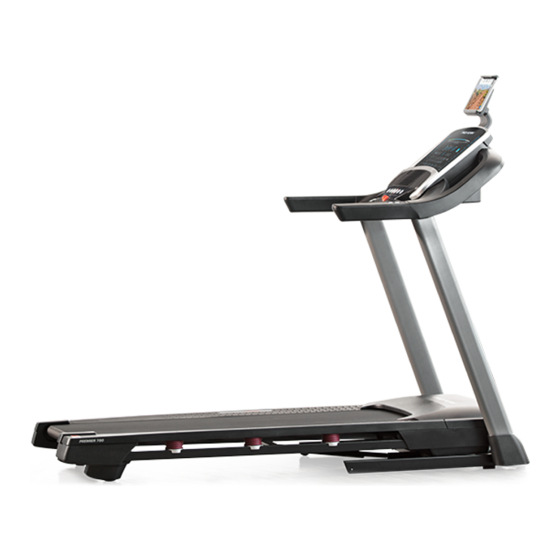
Model No. PFTL79117.0
Serial No.
Write the serial number in the space
above for reference.
Serial Number
Decal
ACTIVATE YOUR
WARRANTY
To register your product and
activate your warranty today, go
to my.proform.com.
CUSTOMER CARE
For service at any time, go to
proformservice.com.
Or call 1-866-362-4490
Mon.–Fri. 6 a.m.–6 p.m. MT
Sat. 8 a.m.–12 p.m. MT
Please do not contact the store.
CAUTION
Read all precautions and instruc-
tions in this manual before using
this equipment. Save this manual
for future reference.
USER'S MANUAL
Advertisement
Table of Contents

Related Manuals for Pro-Form Premier 700


Summary of Contents for Pro-Form Premier 700
- Page 1 proform.com Model No. PFTL79117.0 USER’S MANUAL Serial No. Write the serial number in the space above for reference. Serial Number Decal ACTIVATE YOUR WARRANTY To register your product and activate your warranty today, go to my.proform.com. CUSTOMER CARE For service at any time, go to proformservice.com.
-
Page 2: Table Of Contents
TABLE OF CONTENTS WARNING DECAL PLACEMENT ............. . . 2 IMPORTANT PRECAUTIONS . -
Page 3: Important Precautions
IMPORTANT PRECAUTIONS WARNING: To reduce the risk of burns, fire, electric shock, or injury to persons, read all important precautions and instructions in this manual and all warnings on your treadmill before using your treadmill. ICON assumes no responsibility for personal injury or property damage sus- tained by or through the use of this product. - Page 4 19. Always stand on the foot rails when starting 26. When folding or moving the treadmill, make or stopping the walking belt. Always hold the sure that the storage latch is holding the handrails while using the treadmill. frame securely in the storage position. Do not operate the treadmill while it is folded.
- Page 6 STANDARD SERVICE PLANS...
-
Page 7: Before You Begin
Thank you for selecting the revolutionary PROFORM ® reading this manual, please see the front cover of this PREMIER 700 treadmill. The PREMIER 700 treadmill manual. To help us assist you, please note the product offers an impressive selection of features designed model number and serial number before contacting us. -
Page 8: Part Identification Chart
PART IDENTIFICATION CHART Use the drawings below to identify small parts used for assembly. The number in parentheses below each draw- ing is the key number of the part, from the PART LIST near the end of this manual. The number following the key number is the quantity used for assembly. -
Page 9: Assembly
ASSEMBLY • To hire an authorized service technician to • Left parts are marked “L” or “Left” and right parts assemble the treadmill, call 1-800-445-2480 are marked “R” or “Right.” • Assembly requires two persons. • To identify small parts, see page 8. •... - Page 10 2. Make sure that the power cord is unplugged. Remove the tie securing the Upright Wire (81) to the front of the Base (94). Next, identify the Right Upright (90). Have a sec- ond person hold the Right Upright near the Base (94).
- Page 11 4. Hold the Right Upright (90) against the Base (94). Make sure not to pinch the Upright Wire (81). Next, hold a Wheel (103) inside the Base (94), and insert a 3/8" x 1 3/4" Screw (62) with a 3/8" Star Washer (13) through the Base and the Wheel as shown;...
- Page 12 6. Identify the left handrail assembly (E). Attach the left handrail assembly to the Left Upright (89) with two 5/16" x 2 1/2" Screws (28) and two 5/16" Star Washers (11); do not fully tighten the Screws yet. Then, remove and discard the indicated screw (F).
-
Page 13: Screws (I), Remove The Pulse Crossbar (93
8. Set the Console Base (64) face down on a soft surface to avoid scratching the Console Base. If there are ties (H) securing the Pulse Crossbar (93) to the Console Base, remove the ties. Next, remove and discard the four indicated screws (I), remove the Pulse Crossbar (93). - Page 14 10. IMPORTANT: To avoid damaging the Pulse Crossbar (93), do not use power tools and do not overtighten the #10 x 3/4" Screws (9). Orient the Pulse Crossbar (93) as shown. Attach the Pulse Crossbar to the Handrails (86) with two #10 x 3/4"...
- Page 15 12. Attach the console assembly (K) to the Pulse Crossbar (93) with four #8 x 1/2" Screws (1); start all four Screws, and then tighten them. Then, firmly tighten the four 5/16" x 3/4" Screws (4). 13. Insert the Upright Wire (81) and the other wire (J) through the two indicated looped ties (L) on the console assembly (K).
- Page 16 14. Insert the wire (J) on the left side through the two indicated looped ties (L) on the console assem- bly (K), and then connect the wire to the wire on the console. Insert all excess wires into the console assembly (K).
- Page 17 16. Note: If the treadmill is assembled on a smooth surface, it may roll forward during this step. Raise the Frame (56) to the upright position. Have a second person hold the Frame until step 18 is completed. Remove the two 5/16" x 3/4" Screws (4) from the Latch Crossbar (38).
- Page 18 18. Remove the 5/16" Nut (12) and the 5/16" x 2 1/4" Bolt (3) from the bracket on the Latch Crossbar (38). Align the upper end of the Storage Latch (53) with the bracket on the Latch Crossbar (38), and insert the 5/16" x 2 1/4" Bolt (3) through the bracket and the Storage Latch.
- Page 19 20. IMPORTANT: You must activate your Console (80) to begin using its exclusive features. First, plug in the power cord (see page 20) and turn on the power (see page 22). Then, using your smart phone or tablet, go to iFit.com/activate and follow the instructions to activate the Console (80).
-
Page 20: How To Use The Treadmill
HOW TO USE THE TREADMILL HOW TO CONNECT THE POWER CORD nominal 120-volt circuit capable of carrying 15 or more amps. To avoid overloading the circuit, do Use a Surge Suppressor not plug other electrical devices, except for low- power devices such as cell phone chargers, into Your treadmill, like other electronic equipment, can be the surge suppressor or into an outlet on the same damaged by sudden voltage changes in your home’s... - Page 21 CONSOLE DIAGRAM FEATURES OF THE CONSOLE To turn on the power, see page 22. To use the man- ual mode, see page 22. To use an onboard workout, IMPORTANT: To activate your console and begin see page 24. To use a custom-focus weight loss using its exclusive features, see assembly step 20 workout, see page 25.
- Page 22 HOW TO TURN ON THE POWER HOW TO USE THE MANUAL MODE IMPORTANT: If the treadmill has been exposed to 1. Insert the key into the console. cold temperatures, allow it to warm to room tem- perature before you turn on the power. If you do See HOW TO TURN ON THE POWER at the left.
- Page 23 5. Change the incline of the treadmill as desired. To reset the displays, press the Stop button repeat- edly. To change the incline of the treadmill, press the Incline increase and decrease buttons or one of the 7. Measure your heart rate if desired. Quick Incline buttons.
- Page 24 8. Turn on the fan if desired. 4. Start the workout. The fan features several Press the Start button. A moment after you press speed settings. Press the the button, the treadmill will automatically adjust to fan buttons repeatedly to the fi...
- Page 25 HOW TO USE A CUSTOM-FOCUS WEIGHT LOSS 6. Measure your heart rate if desired. WORKOUT See step 7 on page 23. 1. Insert the key into the console. 7. Turn on the fan if desired. See HOW TO TURN ON THE POWER on page 22. See step 8 on page 24.
- Page 26 3. Connect your tablet to the console. HOW TO CONNECT YOUR HEART RATE MONITOR TO THE CONSOLE Press the iFit Sync button on the console; the console pairing number will appear in the display. The console is compatible with all BLUETOOTH Smart Then, follow the instructions in the iFit Bluetooth heart rate monitors.
- Page 27 THE SETTINGS MODE HOW TO USE THE TABLET HOLDER The console features a settings mode that keeps track IMPORTANT: The tablet holder is designed for use of treadmill usage information and allows you to select with most full-size tablets. Do not place any other a unit of measurement for the console.
-
Page 28: Fcc Information
FCC INFORMATION This console has been tested and found to comply with the limits for a Class B digital device, pursuant to part 15 of the FCC Rules. These limits are designed to provide reasonable protection against harmful interference in a residential installation. This equipment generates, uses, and can radiate radio frequency energy and, if not installed and used in accordance with the instructions, may cause harmful interference to radio communications. -
Page 29: How To Fold And Move The Treadmill
HOW TO FOLD AND MOVE THE TREADMILL HOW TO FOLD THE TREADMILL HOW TO MOVE THE TREADMILL To avoid damaging the treadmill, adjust the incline Before moving the treadmill, fold it as described at the to zero before you fold the treadmill. Then, remove left. -
Page 30: Maintenance And Troubleshooting
MAINTENANCE AND TROUBLESHOOTING MAINTENANCE c. Check the power switch located on the treadmill frame near the power cord. If the switch protrudes Regular maintenance is important for optimal perfor- as shown, the switch has tripped. To reset the mance and to reduce wear. Inspect and properly tighten power switch, wait for fi... - Page 31 SYMPTOM: The incline of the treadmill does not c. Your treadmill features a walking belt coated with change correctly high-performance lubricant. IMPORTANT: Never apply silicone spray or other substances to a. Calibrate the incline system (see page 27). the walking belt or the walking platform unless instructed to do so by an authorized service SYMPTOM: The walking belt slows when walked on representative.
- Page 32 b. If the walking belt slips when walked on, fi rst SYMPTOM: The tablet holder does not stay in place remove the key and UNPLUG THE POWER CORD. Using the hex key, turn both idler roller a. Rotate the tablet holder backwards. Then, tighten screws clockwise, 1/4 of a turn.
-
Page 33: Exercise Guidelines
EXERCISE GUIDELINES Burning Fat—To burn fat effectively, you must exer- WARNING: cise at a low intensity level for a sustained period of Before beginning this time. During the first few minutes of exercise, your or any exercise program, consult your physi- body uses carbohydrate calories for energy. -
Page 34: Part List
PART LIST Model No. PFTL79117.0 R1217A Key No. Qty. Description Key No. Qty. Description #8 x 1/2" Screw Cable Tie #8 x 3/4" Screw Drive Roller/Pulley 5/16" x 2 1/4" Bolt #8 x 1" Tek Screw 5/16" x 3/4" Screw Wheel #10 Star Washer Cable Tie... - Page 35 Key No. Qty. Description Key No. Qty. Description Isolator Bottom Base Pad 1/4" x 1 1/4" Screw Left Inner Base Cover Key/Clip – User’s Manual Tablet Holder Note: Specifi cations are subject to change without notice. For information about ordering replacement parts, see the back cover of this manual.
-
Page 36: Exploded Drawing
EXPLODED DRAWING A Model No. PFTL79117.0 R1217A... - Page 37 EXPLODED DRAWING B Model No. PFTL79117.0 R1217A...
- Page 38 EXPLODED DRAWING C Model No. PFTL79117.0 R1217A...
- Page 39 EXPLODED DRAWING D Model No. PFTL79117.0 R1217A...
-
Page 40: Ordering Replacement Parts
ORDERING REPLACEMENT PARTS To order replacement parts, please see the front cover of this manual. To help us assist you, be prepared to provide the following information when contacting us: • the model number and serial number of the product (see the front cover of this manual) •...