
Related Manuals for Pentair FLECK 2815


Summary of Contents for Pentair FLECK 2815
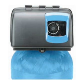
- Page 1 FLECK 2815 WATER SOFTENER OR FILTER CONTROL VALVE SERVICE MANUAL waterpurification.pentair.com...
-
Page 2: Table Of Contents
JOB SPECIFICATION SHEET TABLE OF CONTENTS JOB SPECIFICATION SHEET ............ 2 Job Number: ______________________________________________ OPERATING PARAMETERS ............3 Model Number: ____________________________________________ INSTALLATION ................. 4 Water Hardness: _________________________________ppm or gpg START-UP INSTRUCTIONS Capacity Per Unit: __________________________________________ (ELECTROMECHANICAL TIMER ONLY) ........5 Mineral Tank Size (Height x Diameter): _________________________ 3200 TIMER SETTING PROCEDURE ........ -
Page 3: Operating Parameters
OPERATING PARAMETERS IMPORTANT PLEASE READ: • The information, specifications and illustrations in this manual are based on the latest information available at the time of release. The Minimum Pressure 20 psi/1.38 bar/138 kPa manufacturer reserves the right to make changes at any time without Maximum Pressure 125 psi/8.62 bar/862 kPa notice. -
Page 4: Installation
INSTALLATION Installation Locations FOR DRY LOCATIONS ONLY. Water Pressure A minimum of 20 psi/1.38 bar/138 kPa water pressure is Bypass Valves required for control valve to operate effectively. Always provide for the installation of a bypass valve if unit is CAUTION Water pressure is not to exceed 125 psi (8.6 bar), not equipped with one. -
Page 5: Start-Up Instructions (Electromechanical Timer Only)
INSTALLATION Continued 6. Close and secure the control box cover. 7. Put salt in the brine tank. 14. Manually advance the control valve through the cycle Do not use granulated or rock salt. positions (checking for leaks at each position) and Salt level must always be above water level in brine tank. -
Page 6: 3200 Timer Setting Procedure
3200 TIMER SETTING PROCEDURE How To Set Days On Which Water Conditioner Is To Regenerate (Figure 4) Rotate the skipper wheel until the number “1” is at the red pointer. Set the days that regeneration is to occur by sliding tabs on the skipper wheel outward to expose trip fingers. -
Page 7: 3210 Timer Setting Procedure
3210 TIMER SETTING PROCEDURE Typical Programming Procedure Calculate the gallon capacity of the system, subtract the necessary reserve requirement and set the gallons available opposite the small white dot on the program wheel gear (Figure 54). NOTE: Drawing shows 8,750 gallon setting. The capacity (gallons) arrow (15) shows zero gallons remaining. -
Page 8: 3200, 3210 Regeneration Cycle Setting Procedure
3200, 3210 REGENERATION CYCLE SETTING PROCEDURE How To Set The Regeneration Cycle Program The regeneration cycle program on your water conditioner has been factory preset, however, portions of the cycle or program may be lengthened or shortened in time to suit local conditions. -
Page 9: 3200 Time Clock Timer Assembly
3200 TIME CLOCK TIMER ASSEMBLY EXPLODED VIEW NO SCALE EXPLODED VIEW NO SCALE 62018 Rev A Item No. Part No. Description 1....1 ..62018-10 ....Timer Assy, EM, 2815, 12 Day, 60Hz 1 ..62018-11 ....Timer Assy, EM, 2815, 12 Day, 50Hz 1 .. -
Page 10: 3210 Meter Delayed Timer Assembly
3210 METER DELAYED TIMER ASSEMBLY 62019 Rev A Item No. Part No. Description 1....1 ..62019-11 ....Timer Assy, EM, 2815, Delay, 60Hz 1-1/2”STD 1 ..62019-12 ....Timer Assy, EM, 2815, Delay, 50Hz 1-1/2”STD 1 ..62019-13 ....Timer Assy, EM, 2815, Delay, 60Hz 1-1/2”, 40M3, EXT 1 .. -
Page 11: Sxt Timer Assembly
SXT TIMER ASSEMBLY 62066 Rev A Item No. Part No. Description 1....1 ..62066 ....Timer Assy. SXT, DC, 2815 Not Shown 1 ..62057 ....Kit, Wire Harness, DC 1 ..44164 ....Power Supply, Intl, 24V DC 3M, 2A FLECK • 11 2815 Control Valve Service Manual... -
Page 12: Xtr2 Timer Assembly
XTR2 TIMER ASSEMBLY 62067 Rev A Item No. Part No. Description 1....1 ..62067 ....Timer Assy, XTR2, 2815 Not Shown 1 ..62057 ....Kit, Wire Harness, DC 1 ..44164 ....Power Supply, Intl, 24V DC 3M, 2A 12 • FLECK 2815 Control Valve Service Manual... -
Page 13: 2815 Electromechanical Control Valve Assembly
2815 ELECTROMECHANICAL CONTROL VALVE ASSEMBLY Item No. Part No. Description 1 ....1 ..281501-001 ... 2815, SOF, DNF, CLK, 12DA, 24-60, HW 2--, 1.0, LES, NP4, 1720, HWBP ..281500-003 ... 2815, SOF, DNF, CLK, 7DAY, 24-60, HW 2--, 1.0, LES, NP4, 1720, HWBP .. -
Page 14: 2815 Valve Accessories
2815 VALVE ACCESSORIES Covers 62069-01 .....2815 Black Cover/Blue Bezel, Clear Window 62069-02 .....2815 Black Cover/Black Bezel, Clear Window 62069-03 .....2815 Black Cover/Silver Bezel, Clear Window 62069-04 2815 Black Environmental Cover Meter Assemblies COVER COVER, ENVIRONMENTAL 61933-10 .....Meter Assy, 1-1/2” NPT, STD, SS 61933-11 .....Meter Assy, 1-1/2”... -
Page 15: 2815 Valve Assemblies
2815 VALVE ASSEMBLIES Injector Assemblies 62058 ......Kit, Injector Assembly 44150-01 .....Injector Assy, 1720, #1 VIOLET 44150-02 .....Injector Assy, 1720, #2 BLUE 44150-03 .....Injector Assy, 1720, #3 YELLOW 44150-04 .....Injector Assy, 1720, #4 GREEN 44150-05 .....Injector Assy, 1720, #5 WHITE 44150-06 .....Injector Assy, 1720, #6 RED Injector Screen 44071 ......Injector Screen, 2815 Brine Valves... -
Page 16: 2815 Control Valve Assembly
2815 CONTROL VALVE ASSEMBLY BACK VIEW FRONT VIEW 61500-2815 Rev A 16 • FLECK 2815 Control Valve Service Manual... - Page 17 2815 CONTROL VALVE ASSEMBLY CONTINUED Item No. Part No. Description 7....1 ..62017 ....Seals and Spacers Kit, 2815 1....1 ..62050-01 ....End Plug / Bypass Piston Sub 8....1 ..17470 ....Cable Guide Assy, Assembly 11.12” x 2.0”R 9....1 ..19608-15 ....Disperser, Commerical 1 ..
-
Page 18: Dlfc Insert Options
FILTER CONVERSION KIT DLFC INSERT OPTIONS 62081 Rev A 1.7-7 8-25 30-45 50-70 Item No. Part No. Description 1....1 ..62081 ....Filter Plate Kit, 2815 Item No. Part No. Description 1....1 ..43773 ....Housing, Internal DLFC KIT, WIRE HARNESS, DC 2....1 .. -
Page 19: 1720 Brine System Assembly
1720 BRINE SYSTEM ASSEMBLY FLOW WASHER MARKING ON THIS SURFACE Item No. Part No. Description 1....1 ..62020-00 ....Brine Valve Assy, No Flow Washer ..62020-10 ....Brine Valve Assy, 1.0 GPM ..62020-20 ....Brine Valve Assy, 2.0 GPM ..62020-50 ....Brine Valve Assy, 5.0 GPM 2....1 .. -
Page 20: 1-1/2 Inch Stainless Steel Meter Assembly
1-1/2 INCH STAINLESS STEEL METER ASSEMBLY Item No. Part No. Description 1....1 ..62049-01 ....Kit, 1” & 1-1/2” Meter, Std 1 ..62049-02 ....Kit, 1” & 1-1/2” Meter, 2....1 ..61933-10 ....Meter Assy, 1-1/2” NPT, Std, SS Inline, Paddle, Univ Cap 1 .. -
Page 21: 2310 Safety Brine Valve
2310 SAFETY BRINE VALVE CHECK HEIGHT Item No. Part No. Description 1....1 ..60014 ....Safety Brine Valve Assy, 2310 2....2 ..10150 ....Grommet, .30 Dia 3....1 ..60068-30 ....Float Assy, 2310, w/30-inch Rod 4....1 ..60002-27 ....Air Check, #500, 27 inches Long .. -
Page 22: 2350 Safety Brine Valve
2350 SAFETY BRINE VALVE Item No. Part No. Description 1....1 ..60038 ....Safety Brine Valve, 2350 1A ....1 ..61024 ....Actuator Assy, 2350 Brine 2....1 ..60028-30 ....Float Assy, 2350, 30-inch Wht ....1 ..60026-30SAN ..Float Assy, 2350, 30-inch Hot Water 3....1 .. -
Page 23: Troubleshooting
TROUBLESHOOTING Problem Cause Correction Water conditioner fails to Electrical service to unit has been Assure permanent electrical service (check fuse, regenerate. interrupted plug, pull chain, or switch) Timer is defective. Replace timer. Power failure. Reset time of day. Hard water. By-pass valve is open. -
Page 24: Water Conditioner Flow Diagrams
WATER CONDITIONER FLOW DIAGRAMS 4 Slow Rinse Position 1 Service Position Hard water enters unit at valve inlet, flows up into injector Hard water enters unit at valve inlet and flows down through the mineral in the mineral tank. Conditioned water enters housing and down through nozzle and throat, around the center tube through the bottom distributor, then flows up piston, down through mineral, enters center tube through... -
Page 25: Flow Data & Injector Draw Rates
FLOW DATA & INJECTOR DRAW RATES FLOW RATES - #1 INJECTOR 1.20 1.00 Total (gpm) 0.80 0.60 Rinse (gpm) 0.40 Draw (gpm) 0.20 0.00 Pressure (psi) FLOW RATES - #2 INJECTOR 2.00 Total (gpm) 1.80 1.60 1.40 Rinse (gpm) 1.20 1.00 0.80 0.60... - Page 26 FLOW DATA & INJECTOR DRAW RATES continued FLOW RATES - #3 INJECTOR 3.00 2.50 Total (gpm) 2.00 1.50 Rinse (gpm) 1.00 Draw (gpm) 0.50 0.00 Pressure (psi) FLOW RATES - #4 INJECTOR 4.50 4.00 Total (gpm) 3.50 3.00 2.50 Rinse (gpm) 2.00 1.50 Draw (gpm)
- Page 27 FLOW DATA & INJECTOR DRAW RATES continued FLOW RATES - #5 INJECTOR 7.00 6.00 Total (gpm) 5.00 4.00 Rinse (gpm) 3.00 2.00 Draw (gpm) 1.00 0.00 Pressure (psi) FLOW RATES - #6 INJECTOR 10.00 9.00 Total (gpm) 8.00 7.00 6.00 Rinse (gpm) 5.00 4.00...
-
Page 28: Dimensions
DIMENSIONS 173.4 6.83 346.9 13.66 81.7 INLET 3.22 DRAIN OUTLET 336.2 13.24 28 • FLECK 2815 Control Valve Service Manual... - Page 29 DIMENSIONS continued DRAIN 1 1/2-11.5 NPT RP 1 1/2-11 (BSP) 218.1 INLET 8.59 112.5 4.43 57.2 2.25 21.6 4" - 8 UN 2A THREAD 3.55 111.8 4.40 224.4 8.84 1 1/2-11.5 NPT RP 1 1/2-11 (BSP) OUTLET 233.1 9.18 81.3 3.20 1/8 NPT INLET TEST PORT 27.4...
- Page 30 DIMENSIONS continued 3.23 COMMUNICATION CABLE ENTRY POWER ENTRY INLET 1 1/2-11.5 NPT RP 1 1/2-11 (BSP) 82.8 3.26 30 • FLECK 2815 Control Valve Service Manual...
-
Page 31: System #4
SYSTEM #4 Typical Single Tank Installation with Optional Meter FLECK • 31 2815 Control Valve Service Manual... -
Page 32: System #6
WIRING 2815, Electromechanical 32 • FLECK 2815 Control Valve Service Manual... -
Page 33: Wiring
WIRING Continued 2815, SXT FLECK • 33 2815 Control Valve Service Manual... - Page 34 WIRING Continued 2815, XTR2 34 • FLECK 2815 Control Valve Service Manual...
-
Page 35: Piston Assembly/Seal And Spacer Cartridge Replacement
PISTON ASSEMBLY/SEAL AND SPACER 24. Restore water supply to valve (purging air). Cycle valve to backwash to purge the air from the system. Refer CARTRIDGE REPLACEMENT to startup instructions for more information about pressurizing the system. 1. Turn off water supply to valve. 25. -
Page 36: Brine Assembly Replacement
INJECTOR REPLACEMENT MOTOR DRIVE ASSEMBLY REPLACEMENT 1. Turn off water supply to valve. 2. Open/remove the powerhead assembly cover 1. Turn off water supply to valve. 3. Cycle valve to backwash position. Wait until there 2. Open/remove the powerhead assembly cover is no water flow at the drain to ensure the unit is 3. - Page 37 FLECK • 37 2815 Control Valve Service Manual...
- Page 38 38 • FLECK 2815 Control Valve Service Manual...
- Page 39 FLECK • 39 2815 Control Valve Service Manual...
- Page 40 © 2018 Pentair Residential Filtration, LLC. All rights reserved. §For a detailed list of where Pentair trademarks are registered, please visit waterpurification.pentair.com/brands. Pentair trademarks and logos are owned by Pentair plc or its affiliates. Third party registered and unregistered trademarks and logos are the property of their respective owners.