
Related Manuals for Mira EXCEL


Summary of Contents for Mira EXCEL
- Page 1 SHOWER FITTINGS MIRA EXCEL THERMOSTATIC BATH AND SHOWER MIXER Installation & User Guide These instructions are to be left with the user...
-
Page 2: Table Of Contents
CONTENTS Introduction ..................... 3 Description ....................3 Important Safety Information ..............3 Pack Contents Checklist ................. 4 Dimensions ..................... 5 Specifications ..................6 Connections ..................6 Weight ....................6 Temperature Control ................6 Flow Control ..................6 Operating Parameters ................7 Inlet Supply Pressure ................ -
Page 3: Introduction
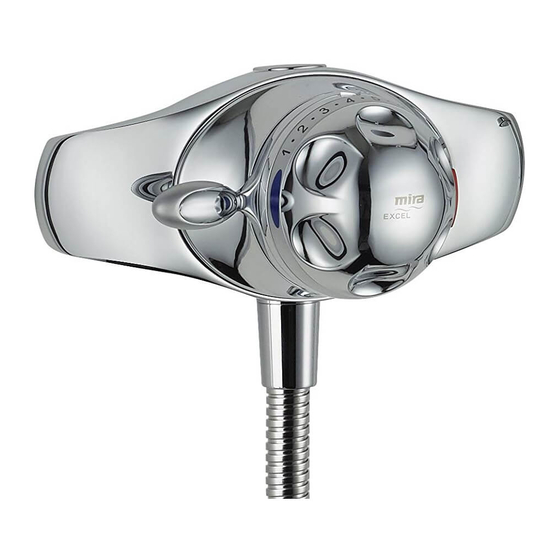
DESCRIPTION This Mira Excel BSM is a fully thermostatic Bath and Shower mixer, with an integral flow control and divertor. A patented temperature re-setting mechanism automatically reduces the maximum allowable temperature when diverting from bath to shower outlet. -
Page 4: Pack Contents Checklist
PACK CONTENTS CHECKLIST Tick the appropriate boxes to familiarise yourself with the part names and to confirm that the parts are included. 1 x Mira Excel BSM 1 x Gasket 2 x Backnut Adaptors 2 x Backnuts 1 x Quad Key... -
Page 5: Dimensions
DIMENSIONS G1/2" Shower G3/4" Inlets NOTE:- NOT TO SCALE - All dimensions are in millimetres... -
Page 6: Specifications
The connections, when viewed from the front, are: Hot – left, Cold – right. Shower Outlet: 1/2" BSP Male. Mira Excel BSM is a fully thermostatic bath and shower mixer with an integral flow control and divertor. It is recommended that Mira Logic Shower fittings with a 1.25 m hose are used with this mixer to optimise performance. -
Page 7: Operating Parameters
Operating Parameters Inlet Supply Pressure Maintained Inlet Pressures: 0.2 - 5 bar Max. Static Pressures: 10 Bar Note! With low pressure systems (below 1 bar) it may be necessary to remove the flow regulators fitted to the product as supplied, refer to section: 'Maintenance, Flow Regulator Removal'. -
Page 8: Installation Requirements
Do not install the product in a position in which service access is restricted. Do not fit any form of flow control in the shower outlet, only Mira recommended fittings should be used. Do not use excessive force when making connections. -
Page 9: Typical Suitable Installations
Typical Suitable Installations Key to symbols appearing throughout this guide. Twin impeller inlet pump Float operated valve Tempering valve Stop or servicing valve Mini expansion vessel Warning or overflow pipe Non-return valve Drop tight pressure reducing valve (PRV) Instantaneous gas-heated supplies (e.g. combination boilers) The BSM MUST be installed with a multipoint gas water heater or combination boiler of a fully modulating design (i.e. - Page 10 Gravity fed supplies The BSM MUST be fed from a cold water storage cistern and hot water cylinder providing nominally equal pressures. Note! For gravity fed supplies you must remove the hot and cold inlet flow regulators and the outlet flow regulator to make sure that the maximum flow rate is achieved. Refer to section: 'Maintenance, Flow regulator Removal'.
- Page 11 Unvented mains pressure supplies The BSM can be installed with an unvented, stored hot water cylinder. Only a "competent person" as defined by Part G of Schedule 1 of the Building Regulations may fit this type of system. For packages with no cold water take off after the appliance reducing valve, it will be necessary to fit an additional drop tight pressure reducing valve when the mains pressure is over 5 bar.
- Page 12 Pumped supplies (inlet pumps) The BSM can be installed with an inlet pump (twin impeller). The pump MUST be located on the floor next to the hot water cylinder. The hot water cylinder/vent pipes must be arranged as shown to achieve air separation. 90°...
-
Page 13: Installation
INSTALLATION The Mira Excel Thermostatic BSM can be installed on most standard baths and deck surfaces (refer to illustration). Fit the bath sealing gasket to the mixer with the arrow pointing forward. Carefully position on the bath (refer to illustration). - Page 14 Install the shower fittings, refer to the appropriate section in the Shower Fittings Installation and User Guide. 10. Connect the shower hose to the shower outlet of the Excel BSM. 11. This completes the installation of the Mira Excel BSM.
-
Page 15: Operation
OPERATION The Mira Excel BSM is fitted with a separate On / Off flow divertor and temperature control handle which operate as follows:- On / Off Flow Divertor From the Off position, anticlockwise movement immediately turns on the flow to bath mode, full clockwise movement diverts the flow to shower mode. -
Page 16: Commissioning
Maximum Temperature The maximum blend temperature through the bath or shower outlet should be limited to prevent accidental selection of a temperature which may be too hot. All Mira thermostatic mixing valves are fully performance tested individually and the maximum temperature for the Mira Excel BSM is pre-set under ideal installation conditions at the factory to approximately 46°C for bath fill. -
Page 17: Maximum Temperature Setting
Maximum Temperature Setting Pull off the temperature control knob. Remove the hub screw using the 3 mm hexagonal wrench (supplied) and remove the temperature control hub. Rotate the flow divertor lever to bath mode. Rotate the cartridge temperature spindle using the temperature control hub until the desired bath outlet temperature is obtained from the bath spout. -
Page 18: Fault Diagnosis
FAULT DIAGNOSIS Read the section: Important Safety Information first. Provided that the BSM has been correctly installed and is operated in accordance with the instructions contained in this guide, difficulties should not arise. If any maintenance is required then it must be carried out by a competent tradesperson for whom the fault diagnosis chart and maintenance instructions are provided. - Page 19 Symptom Cause/Rectification Flow rate too low or (Too low) Insufficient supply pressures. too high. (Too low) Refer to symptom 2. (Too high) Supply pressure too high. Flow regulators fitted incorrectly. Dripping from bath Remove the flow divertor cartridge and check the or shower outlet.
-
Page 20: Maintenance
The Mira Excel BSM is designed for the minimum of maintenance in normal use. If a malfunction occurs with either the temperature control cartridge or the flow divertor cartridge then this will necessitate a complete cartridge replacement. - Page 21 Start Measure and record supply temperatures, pressures and make sure that they are within the valve specification. Measure and record blend temperature (Tb) and flow rate. flow rate fallen Check and clean checkvalves, significantly or fallen below strainers and outlets. minimum flow specification Measure and record blend...
-
Page 22: Flow Regulator Removal
For combination boilers a fourth (white) flow regulator is supplied with the product to make sure that the boiler can supply the Excel BSM with an adequate supply of hot water. You must replace only the green flow regulator supplied installed in the hot inlet and replace it with the white flow regulator (supplied). - Page 23 17. Refit the temperature control hub, tighten the hub screw and refit the temperature control knob. Refer to section: 'Maximum Temperature Setting'. Temperature Control Knob Hub Screw Temperature Shower Outlet Nipple Control Hub Flow Divertor Lever Red Flow Regulator Retaining Screws Flow Divertor Lever Slip Ring...
-
Page 24: Filter Cleaning/Replacement
Filter Cleaning/Replacement Blockage of the inlet filters can lead to poor flow performance and reduced temperature control. It is essential that the inlet filters are periodically cleaned or, if necessary, renewed as part of a preventative maintenance programme. Turn off the hot and cold water supplies. Pull off the temperature control knob. - Page 25 Temperature Control Knob Hub Screw Temperature Control Hub Flow Divertor Lever Retaining Screws Shower Outlet Nipple Flow Divertor Lever Slip Ring Cover Shroud Body Retaining Screws Body Filter Cap Manifold Filter COLD...
-
Page 26: Maintaining The Non-Return Valves
Maintaining the Non-Return Valves The non-return valves are located inside the inlet manifold and inside the shower outlet nipple. Note! For the shower only perform instructions 2 to 4. Turn off the hot and cold water supplies. Disconnect the shower hose and remove the shower outlet nipple using the quad key (supplied) or a 12 mm hexagonal wrench. - Page 27 19. Refit the temperature control hub, tighten the hub screw and refit the temperature control knob. Refer to section: 'Maximum Temperature Setting'. Temperature Control Knob Hub Screw Temperature Control Hub Shower Outlet Nipple Flow Divertor Lever Red Flow Regulator Retaining Screws Flow Divertor Lever Slip Ring...
-
Page 28: Removing The Thermostatic Cartridge
Removing the Thermostatic Cartridge Turn off the hot and cold water supplies. Pull off the temperature control knob. Unscrew the hub screw using the 3 mm hexagonal wrench (supplied) and remove the temperature control hub. Unscrew the 2 flow divertor lever retaining screws using the 3 mm hexagonal wrench (supplied) and remove the flow divertor lever and slip ring. - Page 29 Temperature Control Knob Hub Screw Temperature Control Hub Flow Divertor Shower Outlet Nipple Lever Slip Ring Cover Shroud Screw Screw Temperature Control Gear Temperature Setting Tool Flow Control Gear Temperature Stop Sleeve Idler Gear Cartridge Spacer Thermostatic Cartridge Body...
-
Page 30: Cleaning And Re-Assembly Of The Thermostatic Cartridge
Cleaning and Re-assembly of the Thermostatic Cartridge The interior surface of the Bath and Shower Mixer body must be clean before refitting the cartridge. If scale or deposits are present, clean using a mild proprietary inhibited scale solvent, e.g. domestic kettle descalent. After descaling, rinse valve interior thoroughly in clean water before refitting the cartridge. - Page 31 Line up the temperature control gear with the cartridge spacer, push on and rotate anti-clockwise through 180°. 10. Refit the flow control gear and line up with temperature control gear using the temperature setting tool. 11. Refit the idler gear and tighten the screw. Caution! Do not overtighten the screw as damage may occur causing the idler gear to jam on the bush.
-
Page 32: Replacement Of The Flow Cartridge
Replacement of the Flow Cartridge Turn off the hot and cold water supplies. Pull off the temperature control knob. Unscrew the hub screw using the 3 mm hexagonal wrench (supplied) and remove the temperature control hub. Unscrew the 2 flow divertor lever retaining screws using the 3 mm hexagonal wrench (supplied) and remove the flow divertor lever and slip ring. - Page 33 23. Turn on the hot and cold water supplies and check for any leaks. 24. Set the Maximum Temperature. Refer to section: 'Maximum Temperature Setting'. Temperature Control Knob Screw Temperature Control Hub Flow Divertor Lever Retaining Screws Nipple Flow Divertor Lever Slip Ring Cover Shroud...
-
Page 34: Spares
Temperature Adjustment Pack (items shown as A) 1598.024 Handle Pack 1598.025 Shower Nipple Assembly 1598.035 Cover Shroud Pack 1598.036 Flow Regulator Kit 1598.037 Check Valve Assembly ACCESSORIES Available as an optional accessory from your local Mira Stockist 1598.009 3/4" Isolating Flexible Inlet Hose, 500 mm (2) - Page 35 Spare Parts Diagram 1598.025 1598.024 1598.036 1598.035 462.08 462.16 1598.022 462.06 462.10 1598.037 462.04 462.01 462.05...
-
Page 36: Customer Service
CUSTOMER SERVICE 1056991-W2-A © Kohler Mira Limited, January 2006...