
Related Manuals for Mira Excel


Summary of Contents for Mira Excel
- Page 1 MIRA EXCEL SHOWER CONTROL Installation & User Guide These instructions are to be left with the user...
-
Page 2: Table Of Contents
1. Back inlet supplies (rising or falling concealed pipework) ....14 2. Exposed supplies (rising or falling surface pipework) ....17 Excel B ....................22 3. Solid and dry-lined walls..............22 4. Stud Partitions and Shower Enclosures (Front Face) ..... 28 5. -
Page 3: Introduction
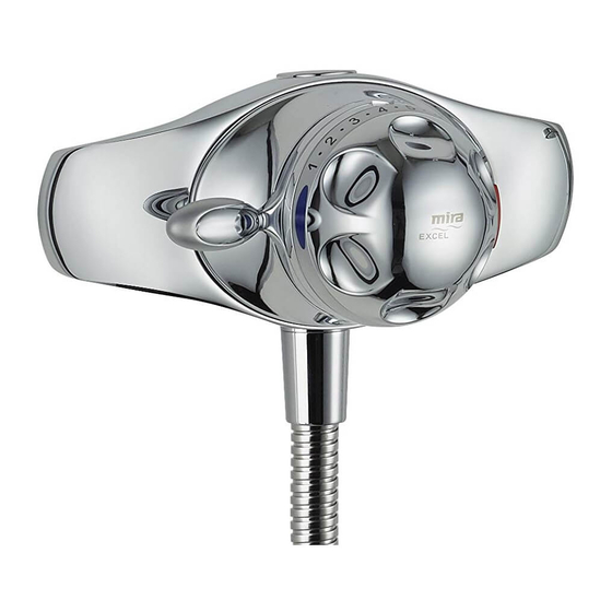
INTRODUCTION Thank you for purchasing a quality Mira product. To enjoy the full potential of your new product, please take time to read this guide thoroughly, having done so, keep it handy for future reference. The Mira Excel is a thermostatic shower control with independent selection of spray force and temperature. -
Page 4: Important Safety Information
IMPORTANT SAFETY INFORMATION Warning! Products manufactured by us are safe and without risk provided they are installed, used and maintained in good working order in accordance with our instructions and recommendations. Caution! Read all of these instructions. Retain this guide for later use. Pass on this guide in the event of change of ownership of the installation site. -
Page 5: Pack Contents Checklist
PACK CONTENTS CHECKLIST Tick the appropriate boxes to familiarize yourself with the part names and to confirm that the parts are included. Excel shower control 1 x Excel 1 x O-Key 2 x Compression Nuts 2 x No. 8 x 3/4" Screws... - Page 6 Excel B shower control 1 x Excel B (with building-in shroud) 1 x Concealing 1 x Shroud Plate Assembly 2 x No.8 x 1 1/4" Screws 1 x Knob Assembly 4 x M5 x 50 mm Screws (2 fitted) 2 x M4 x 30 mm Screws...
-
Page 7: Dimensions
DIMENSIONS Excel 150 - 155 NOTE:- NOT TO SCALE - All dimensions are nominal and in millimetres Excel B 61 - 78... -
Page 8: Specifications
SPECIFICATIONS 1. Pressure Ranges Excel & Excel B 1.1. Minimum maintained pressure: 0.1 bar (1.0 metre head) when used with Mira shower fittings. 1.2. Maximum maintained pressure: 5.0 bar. 1.3. Maximum static pressure: 10 bar. Note! Nominally equal inlet supply pressures are recommended for optimum performance. -
Page 9: Flow Rates
4. Flow Rates EXCEL WITH LOGIC FITTINGS HIGH CAPACITY SPRAY PLATE Pressure Loss (Bar) EXCEL WITH LOGIC FITTINGS LOW CAPACITY SPRAY PLATE Pressure Loss (Bar) Note! Pressure conversion: 1 bar = 10 m head of water = 100 kPa... -
Page 10: Installation Requirements
Do not install the product in a position in which service access is restricted. Do not fit any form of flow control in the shower outlet, only Mira recommended fittings should be used. - Page 11 Instantaneous gas-heated showers (e.g. combination boilers) The shower control MUST be installed with a multipoint gas water heater or combination boiler of a fully modulating design (i.e. where the water draw-off rate indirectly controls the gas flow rate to the burner). A drop tight pressure reducing valve MUST be fitted if the supply pressures exceed 5 bar maintained.
- Page 12 Unvented mains pressure showers The shower can be installed with an unvented, stored hot water cylinder. Only a "competent person" as defined by Part G of Schedule 1 of the Building Regulations may fit this type of system. For packages with no cold water take off after the appliance reducing valve, it will be necessary to fit an additional drop tight pressure reducing valve when the mains pressure is over 5 bar.
- Page 13 Mains pressurised instantaneous hot water shower, heated from a thermal store Packages of this type, fitted with a tempering valve can be used. A drop tight pressure reducing valve MUST be fitted if the supply pressures exceed 5 bar maintained. An expansion vessel MUST be fitted (and regularly maintained) if any form of backflow prevention device is fitted, e.g.
-
Page 14: Installation
INSTALLATION Excel 1. Back inlet supplies (rising or falling concealed pipework) Read the section: Installation Requirements first. 1.1 Decide on a suitable position for the shower control. The position of the shower control and the shower fittings must provide a minimum gap of 25... - Page 15 1.5 Use a spirit level and pencil to mark the route of the hot and cold water supply pipes at 150-155mm centres. Note! The Excel is supplied with inlet connections hot left, cold right and bottom outlet as standard. For...
- Page 16 1.11 Slide the compression nuts and olives Olive over the supply pipes. Compression Backplate 1.12 Locate the Excel shower control on to the backplate and supply pipes and hold it in position. Screws Note! Align the adjustable inlets to aid location onto the pipework.
-
Page 17: Exposed Supplies (Rising Or Falling Surface Pipework)
2. Exposed supplies (rising or falling surface pipework) Read the section: Installation Requirements first. Rising Supplies 2.1 Decide on a suitable position for the shower control. The position of the Hose Retaining Ring shower control and the shower fittings must provide a minimum gap of 25 25 mm Minimum mm between the spill-over level of the shower tray/bath and the handset. - Page 18 Inlet Nipples screwdriver. O-Key Inlet Nipple Bolts 2.11 Locate the Excel shower control on to the backplate. 2.12 Use a suitable screwdriver to tighten the two screws in the backplate. The screws will hold the shower control in position. Do not overtighten the...
- Page 19 150-155 mm centres. Use the installation template to make sure the pipes are in the right position. Note! The Excel is supplied with inlet connections hot left, cold right and bottom outlet as standard. For installations with reversed hot and cold...
- Page 20 Tighten the outlet blanking plug with the O-Key. 2.24 Fit the outlet cap correctly. The matching contours of the outlet cap and shower control body must be aligned. 2.25 Locate the Excel shower control on to the backplate. Tapered End...
- Page 21 2.26 Use a suitable screwdriver to tighten the two screws in the backplate. The screws will hold the shower control in Backplate position. 2.27 Install the hot and cold supply pipes 38 mm from the finished wall at 150-155 mm centres. Use the installation template to ensure the pipes are in the right position.
-
Page 22: Excel B
Excel B 3. Solid and dry-lined walls Read the section: Installation Requirements first. The built-in shower control is supplied with a support bracket that can be used to install the shower control into a solid or dry-lined wall structure. A foam seal is fitted to the concealing plate assembly to seal the bracket to the wall surface (i.e. - Page 23 3.4 If installing the shower into a solid wall, mark an opening sufficient to accommodate the shower control approximately 245 mm x 145 mm on the surface of the wall. Alternatively, if installing the shower into a dry-lined wall, use the installation template and mark around 245 mm the outside edge.
- Page 24 Failure to do so may result in product malfunction. Note! The Excel B is supplied with inlet connections hot left, cold right and top outlet as standard. For installations with reversed hot and cold refer to section: Reversed inlet connections.
- Page 25 3.13 Loosely attach the compression nuts Compression Nut Olive Threads and olives. 3.14 Fit the support bracket and valve unit in to the wall with the two fixing screws. 3.15 Insert the hot and cold supply and top outlet pipes through the compression nuts and olives.
- Page 26 3.20 When the plaster/tiles have set, remove the screws and pull the entire building-in shroud away. Note! Retain the screws for later use. 3.21 Remove the backplate from the concealing plate. Remove the protective film from foam seal and fit in position with the four fixing screws (supplied).
- Page 27 3.23 Fit the control assembly, refer to section: Control Assembly Fitting Instructions. 3.24 Install the shower fittings. Refer to the shower fittings Installation and User Guide.
-
Page 28: Stud Partitions And Shower Enclosures (Front Face)
4. Stud Partitions and Shower Enclosures (Front Face) Read the section: Installation Requirements first. The built-in shower control is supplied with a support bracket that can be used to install the shower control into the front face of a stud partition wall structure or shower enclosures. -
Page 29: Laminated Panels And Shower Enclosures (Rear Face)
5. Laminated Panels and Shower Enclosures (Rear Face) Read the section: Installation Requirements first. The built-in shower control is supplied with a support bracket that can be used to install the shower control onto the rear face of a laminated panel or preformed shower cubicle. - Page 30 5.6. Remove the outer sections of the building-in shroud and fix the support bracket and valve in position using the two M4 x 30 mm screws (supplied). 5.7. Align the hot and cold supply and top M4 x 30 mm Screws outlet pipes with the valve but do not secure the pipes.
-
Page 31: Control Assembly Fitting Instructions
CONTROL ASSEMBLY FITTING INSTRUCTIONS The procedure below details the steps required to fit the control assembly. The procedure is applicable to both the exposed and built-in versions. Blue Make sure that the temperature hub is turned to the position illustrated and that the flow stop is at the bottom. -
Page 32: Reversed Inlet Connections
The Excel is supplied with inlet connections hot left, cold right and bottom outlet. The Excel B is supplied with inlet connections hot left, cold right and top outlet as standard. If the hot and cold water supply pipes have been reversed during installation the following procedure must be performed. - Page 33 Make sure that the large cartridge seal is first located in the shower control body Cartridge Cartridge Retaining Screw Inlet Seal Shroud Control Assembly...
-
Page 34: Commissioning
COMMISSIONING 1. Maximum temperature setting All Mira Excel shower controls are fully performance tested and the maximum temperature has been set under ideal installation conditions at the factory. The temperature stop is set to 41 °C and depressing the override will increase the temperature by 5 °C to approximately 46 °C. - Page 35 1.7 Turn the shower on. Rotate the temperature spindle until the required temperature is obtained. Turn the temperature spindle anticlockwise to increase the temperature or clockwise to decrease the temperature. If resistance is felt DO NOT USE FORCE to rotate the spindle as this is maximum obtainable Clockwise to...
-
Page 36: Maximum Temperature Settings For Reversed Inlet Connections
2. Maximum Temperature Settings for Reversed Inlet Connections Refer to section:Commisioning, 1. Maximum temperature setting, sections 1.1 to 1.8 for the initial setting. 2.1 Refit the temperature hub so that the two small lugs on the front, align with the arrows on the top and bottom on the temperature indicator trim, ensuring that the stop on the rear of the hub is Arrows... -
Page 37: Temperature Override Button - Disable
3. Temperature override button - disable The Excel incorporates a temperature override button that allows the user to override the preset maximum temperature. The following procedure can be used to disable the override button, limiting the maximum temperature available to the preset value. -
Page 38: Operation
OPERATION 1. Excel and Excel B The Excel incorporates a temperature override button that allows the user to override the preset maximum temperature. It is recommended that this facility is disabled for the young, the elderly and the infirm, or anyone inexperienced in the correct operation of the controls. -
Page 39: Fault Diagnosis
Fit high capacity spray cycling on and off as plate. flow rate/pressure too Increase flow/pressure low. through system. Contact boiler manufacturer. Raise cistern or fit Mira Head of water below pump. minimum required. Inlet strainer blocked. Clean or renew. Flush pipework before refitting. - Page 40 Malfunction Cause Remedy A B C Other hot or cold draw Do not use other off being used causing outlets whilst wide pressure changes showering. or instantaneous boiler temperature changes. Supply pressures Refer to Section 6, unequal. Installation Requirements. Drip from handset A small amount of This is quite normal.
- Page 41 Malfunction Cause Remedy A B C Shower Hot water temperature Adjust the hot water temperature too less than 12 °C above temperature or wait for cold (maximum the required shower the water to reheat if temperature blend temperature. stored system. correctly set).
- Page 42 (PRV) just after the property incoming mains stopcock, effectively balancing the hot and cold supply pressures. Ideally set the PRV at 3.5 bar. Balance Excel inlet Excel noisy during Unbalanced inlet supply pressures. Fit a operation. supply pressures. drop tight PRV just...
-
Page 43: Maintenance
MAINTENANCE The Mira Excel is designed to be maintenance free, as such there are no serviceable parts in the cartridge. However regular cleaning will keep the shower in pristine condition, refer to 1. Cleaning. Strainers are fitted to the inlets of the mixer to protect the cartridge and will give many years of trouble free showering. -
Page 44: Spare Parts
SPARE PARTS 1. Excel spare parts list 451.67 Hub Pack 451.71 Cartridge Assembly/Inlet Filters 451.72 Inlet Filters 451.74 Component Pack - components identified 'A' 451.76 Seal Pack - components identified 'B' 451.77 Screw Pack - not illustrated 451.81 Temperature Knob/Flow Lever Assembly - chrome 451.82... - Page 45 2. Excel spare parts diagram 451.87 451.88 451.89 1608.019 1608.020 451.71 1608.010 1608.011 451.72 466.01 466.02 1608.010 1608.011 553.35 553.54 451.72 451.67 451.81 451.82 451.83 451.86...
- Page 46 3. Excel B spare parts list 451.61 Building-in Shroud 451.62 Temperature Knob/Flow Lever Assembly - white 451.63 Temperature Knob/Flow Lever Assembly - chrome 451.64 Temperature Knob/Flow Lever Assembly - satin chrome 451.65 Temperature Knob/Flow Lever Assembly - white/gold 451.67 Hub Pack 451.68...
- Page 47 4. Excel B spare parts diagram 466.04 466.03 451.72 451.72 451.71 451.67 451.62 451.63 451.64 451.65 451.68 451.69 451.70 451.78 451.61...
-
Page 48: Customer Service
CUSTOMER SERVICE P3840/4 © Kohler Mira Limited, September 2005...