Table of Contents
Advertisement
Quick Links
Advertisement
Table of Contents

Related Manuals for Amprobe AM91RS


Summary of Contents for Amprobe AM91RS
- Page 1 USER'S USER'S MANUAL MANUAL AM91RS AMPROBE A United Dominion Company...
- Page 2 1) SAFETY This manual contains information and warnings that must be followed for operating the meter safely and maintaining the meter in a safe operating condition. If the meter is used in a manner not specified by the manufacturer, the protection provided by the meter may be impaired.
-
Page 3: Terms In This Manual
TERMS IN THIS MANUAL WARNING identifies conditions and actions that could result in serious injury or even death to the user. CAUTION identifies conditions and actions that could cause damage or malfunction in the instrument. WARNING To reduce the risk of fire or electric shock, do not expose this product to rain or moisture. To avoid electrical shock hazard, observe the proper safety precautions when working with voltages above 60 VDC or 30 VAC rms. -
Page 4: Electromagnetic Compatibility (Emc)
Fuse 2) ELECTROMAGNETIC COMPATIBILITY (EMC) The instrument meets EN55022(1994/A1; 1995/Class B) and EN50082-1(1992) -
Page 5: Product Description
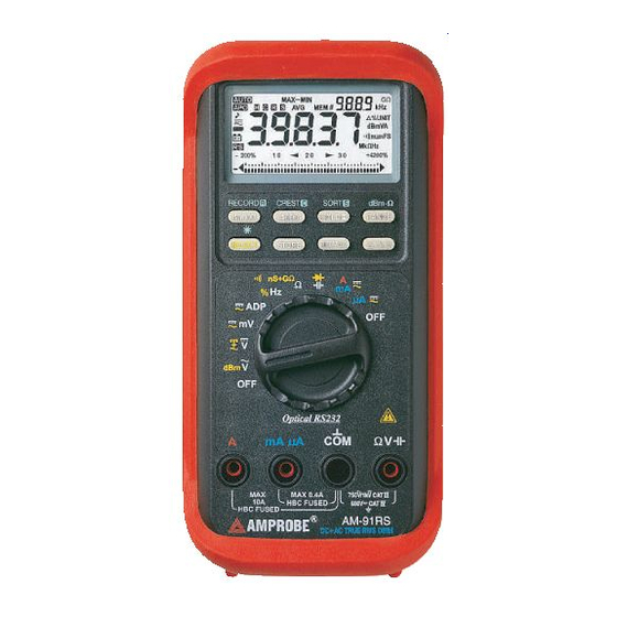
3) PRODUCT DESCRIPTION Panel Illustration 1) 4-3/4 digits 40000 counts LCD display 2) Push-buttons for special functions & features 3) Selector to turn the Power On or Off and Select a function 4) Input Jack for 10A (20A for 30sec) current function 5) Input Jack for all functions EXCEPT current (µA, mA, A) functions... -
Page 6: Analog Bar-Graph
Analog bar-graph The analog bar graph provides a visual indication of measurement like a traditional analog meter needle. It is excellent in detecting faulty contacts, identifying potentiometer clicks, and indicating signal spikes during adjustments. DC+AC True RMS DC+AC True RMS is a term which identifies a DMM that responds accurately to the total effective RMS value regardless of the waveforms such as: square, sawtooth, triangle, pulse trains, spikes, as well as distorted waveforms with the presence of harmonics and DC components. -
Page 7: Operation
4) OPERATION ACV, ACV + Hz, & dBm + Hz functions Defaults at ACV. Press SELECT button momentarily to select ACV + Hz. Press SELECT button momentarily again to select dBm + Hz. Input sensitivity for Hz varies automatically with voltage range selected in ACV + Hz function. It is designed especially for measuring the frequency of high voltage noisy electrical signals. - Page 8 DCV, DC + AC V functions Defaults at DC. Press SELECT button momentarily to select DC + AC. Analog bar- graph will be disabled in the DC + AC mode. Hold The hold function freezes the display for later view. Press the HOLD button momentarily to activate and to exit the hold function...
- Page 9 DC, AC, AC + Hz mV functions Defaults at DC. Press SELECT button momentarily to select AC. Press SELECT button momentarily again to select AC + Hz. DC, AC, AC + Hz Adapter functions The operation of Adapter function is similar to the mV function. Defaults at DC. Press SELECT button momentarily to select AC.
-
Page 10: Backlighted Display
Hz, % + Hz functions Defaults at Hz. Press SELECT button momentarily to select % + Hz. Note: Unlike the AC + Hz function, this high resolution Hz function is set at the highest input sensitivity to measure digital type electronic signals. Backlighted display Press the SELECT button for 1 second or more to turn on and off the display backlight function. - Page 11 Ω Ω Resistance, nS + GΩ Ω Conductance, Continuity functions Default at Ω. Press SELECT button momentarily to select nS + GΩ Conductance for resistance measurement beyond 40MΩ. Press SELECT button momentarily again to select Continuity function which is convenient for checking wiring connections and operation of switches.
-
Page 12: Capacitance, Diode Test Function
Capacitance, Diode test function Default at . Press SELECT button momentarily to select Diode test function. CAUTION Discharge capacitors before making any measurement. Large value capacitors should be discharged through an appropriate resistance load Note: Normal forward voltage drop (forward biased) for a good silicon diode is between 0.400V to 0.900V. - Page 13 µ µ A, mA, and A Current functions Default at DC. Press SELECT button momentarily to select AC. Press SELECT button momentarily again to select AC + Hz. A will be selected automatically when the correct input jack is plugged in. Note: When measuring a 3-phase system, special attention should be taken to the phase to phase voltage which is significantly higher than the phase to earth voltage.
-
Page 14: Record Mode
40000 counts high resolution slow mode Press the 40000 button momentarily to enter the 4-3/4 digit high resolution slow mode. The digital display updates 1.25 times per second nominal to give you smooth readings as well as the full accuracy of the meter. Press the 4000 button momentarily to return to the power up default 3-3/4 digit fast mode. - Page 15 before disconnecting the test leads.
-
Page 16: Manual Or Auto-Ranging
CREST capture mode Press and hold the CREST button for one second or more to activate CREST (Instantaneous peak hold) mode to capture voltage or current signal duration as short as 0.8ms. This mode is available in DCV, ACV, DCA, & ACA functions. The LCD annunciators “C”... - Page 17 Note: Manual ranging feature is not available in Hz function.
- Page 18 SORT mode Press and hold the SORT button for one second or more to activate SORT mode. The LCD annunciators “S” & “MAX-MIN AVG” turn on. SORT only holds & displays stable measurement, and counts the event number by the secondary display. The meter beeps when new stable reading is captured.
-
Page 20: Auto Power Off (Apo)
Relative modes Press the .%.U button momentarily to enter the Relative mode . This allows the meter to set the displaying reading as the reference value and offset (zero) the display. The meter consecutive measurements will then be displayed as the relative reading to the reference value. -
Page 21: Maintenance
feature. Input warning The meter beeps as well as displays “InErr” to warn the user against possible damage to the meter due to improper connections to the µA, mA, or A input jacks when other function (like voltage function) is selected. Line filter frequency selection Press the 40000 button while turning the meter on to display the set frequency. - Page 22 terminal will then be open circuit. The series fusible resistors and the spark gaps should then be replaced by qualified technician. Refer to the LIMITED WARRANTY section for obtaining warranty or repairing service. Battery and Fuse replacement The meter uses a single standard 9V alkaline battery (NEDA1604A, JIS6AM6, IEC6LF22), a 500V/0.63A IR 200kA fast acting F fuse (FS 1) for µA/mA current input, and a 600V/15A IR 100kA fast acting F fuse (FS 2) for A current input.
- Page 23 6) SPECIFICATIONS GENERAL SPECIFICATIONS Display: 3-3/4 digits 4000 counts or 4-3/4 digits 40000 counts selectable (5 digits 99999 counts for Hz), and 4 digits 9999 counts dual display LCD Polarity: Automatic Update Rate: 3-3/4D Data: 5 per second nominal; 4-3/4D Data: 1.25 per second nominal; 43 Segments Bar graph: 128 per second max Low Battery: The indicator appears when the battery voltage drops below approx.
- Page 24 ELECTRICAL SPECIFICATIONS ± ± ± Accuracy is (% reading digits + number of digits) or otherwise specified, at 73 F 41F (23 ) & less than 75% R.H. True RMS ACV, (DC+AC)V, & ACA accuracies are specified from 5 % to 100 % of range or otherwise specified. Maximum Crest Factor <3:1 at full scale & <6:1 at half scale, and with frequency component within the specified frequency bandwidth for non-sinusoidal waveforms DC Voltage RANGE...
- Page 25 AC Adapter 10 counts per 1 mVAC Accuracy : Same as AC 400.0mV range Ω Input Impedance : 1000M , 70pF nominal Temperature coefficient : 0.1 X (Specified accuracy)/ @ 23F - 65F or 83F - 122F (0 or 28 Overload protection : 600VDC/VAC rms AC Voltage RANGE*...
- Page 26 40.00mA 1.0%+4d** 3.3mV/mA 400.0mA 0.8%+3d 3.3mV/mA 4.000A 1.0%+4d** 0.03V/A 10.00A*** 0.8%+3d 0.03V/A 40Hz 300Hz µ µ 400.0 0.15mV/ 1.5%+4d** µ µ 4000 0.15mV/ 1.0%+3d 40.00mA 1.5%+4d** 3.3mV/mA 400.0mA 1.0%+3d 3.3mV/mA 4.000A 1.5%+4d** 0.03V/A 10.00A*** 1.0%+3d 0.03V/A 300Hz 3kHz µ µ 400.0 0.15mV/ Unspec'd...
- Page 27 DC Current RANGE Accuracy Burden Voltage µ µ 400.0 0.15mV/ 0.4% + 4d µ µ 4000 0.15mV/ 0.2% + 2d 40.00mA 0.4% + 4d 3.3mV/mA 400.0mA 0.2% + 3d 3.3mV/mA 4.000A 0.8% + 6d 0.03V/A 10.00A* 0.4% + 4d 0.03V/A µ...
- Page 28 Duty Cycle RANGE Accuracy 0.1% 99.9% 0.5d/kHz µ Input Frequency : 50Hz 250kHz; 5V Logic Family with + & - pulse width Update Rate : 1.2 per second nominal Overload protection : 600VDC/VAC rms Capacitance RANGE Accuracy* 4.000nF** 4.0% + 10d 40.00nF 3.0% + 5d 400.0nF...
- Page 29 Ω At 600 , -5.74dBm to 54.25dBm, ± Accuracy : 0.25dB + 2d (@40Hz 20kHz) Ω Selectable reference impedance of 4, 8, 16, 32, 50, 75, 93, 110, 125, 135, 150, 200, 250, 300, 500, 600, 800, 900, 1000, 1200 Ω...
-
Page 30: Limited Warranty
AMPROBE’s warranty does not apply to accessories, fuses, fusible resistors, spark gaps, batteries or any product which, in AMPROBE’s opinion, has been misused, altered, neglected, or damaged by accident...