Table of Contents
Advertisement
Quick Links
Advertisement
Table of Contents

Related Manuals for Amprobe MEGATEST 5000


Summary of Contents for Amprobe MEGATEST 5000
- Page 1 MEGATEST 5000 5000 V MEGOHMMETER Model#: AMB-5 KVD Owner’s Manual Cra 53 # 50-51 Locales 207-208 Pbx: (4)448 78 30 (4)512 78 30 Barranquilla: 301 362 59 81 Cartagena: 301 362 59 86 Fax: (4)512 75 94 e-mail: suconel@suconel.com www.suconel.com...
- Page 2 Cra 53 # 50-51 Locales 207-208 Pbx: (4)448 78 30 (4)512 78 30 Barranquilla: 301 362 59 81 Cartagena: 301 362 59 86 Fax: (4)512 75 94 e-mail: suconel@suconel.com www.suconel.com...
-
Page 3: Table Of Contents
ACCIDENT PREVENTION AND SAFETY MEASURE S ....................2 ..................................URING USE ..................................FTER USE OV ER V I EW ..................................................................URPOSE OF T HE DEVICE ............................... EASURING PRINCIPLE ............................5 HAT IS INS ULA TION RESISTANCE .......................... -
Page 4: Accident Prevention And Safety Measure S
1. Accident prevention and safety measures Please read and understand these instruct ions BEFORE using the AMB-5KV-D. This instrument can gener ate dangerously high voltages. Only specialised personnel, well trained about electricity and its e ects must use it. When testing, the following is important: •... -
Page 5: After Use
When measuring insulation: Cut power o from the installati on before preparing for the tests. Seal o the testing area and do not allo w other people to approach it throughout the duration of the tests. Seal o the installation being tested, di sconnecting those branches of it which are not involved in the test. -
Page 6: Overview
, we are a leading company in the eld of electrical measuring equipment. Amprobe has been in the marketplace for over 50 years, and intends to satisfy our customers’ requirements by providing in creas ingly reliable and innovative products. -
Page 7: Purpose Of T He Device
Purpose o f the device This instrument can be used to measure the insulation of installations, equipment, insulating material and so on. Testing must be performed with no other vo ltage present, and after having disc onnected the parts not being measured or which are unable to wit hstand the testing voltage. -
Page 8: Other Possible Elds Of Employment
When the meter is in i ts "TIMER" mode, set a dur ation of 10’ to determine the e ciency of an insulator at a certai n voltage. During the test, insulat ion resistance may diminish, remain steady or increase. Diminishing resi stance means insulation is not good. -
Page 9: Notes O N Insul A Tion Measure Ments
Notes on insulation measurem ents Measurement of such a high re s istance as insulation r esistance is very critical, since t he currents involved are minute, even lower than those circulating inside our nervous syste When performing measurements, in order to avoid making mistakes take the following precautions: •... -
Page 10: Preparing The Instrument For Use
3 Preparing the instrument for use 3.1 Initial checks Before being shipped, the instrument is che cked from an electrical and a mechanical point of view. Every precaution has been taken so the inst rument can be deliver ed without damage. Howev er the user is advised to look the instru ment over quickly in or der to check for any damage during shipm ent. -
Page 11: Working Instructions
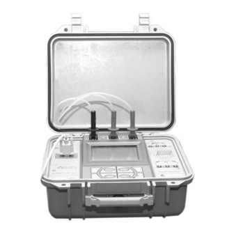
4 Working instructions Description of the instrument Legend: 1. Instrument ON/OFF switch. 2. Negative high voltage jack. 3. GUARD jack. 4. Positive high voltage jack. 5. An example of measurement connection using the GUARD. 6. Measuring range graph. 7. Display. 8. -
Page 12: Display
4.2 Display Legend: 1. "Measuring underway" indicators. When ashing: voltage delivery; when xed ON: circuit discharge. 2. "Measured value" indic ator or indication of the current parame ter memory number. 3. Unit of measure. 4. "Low Battery” indicator. 5. "Current measuring mode" indicator. 6. -
Page 13: Keyboard
4.3 Keyboard Legend: 1. Decrease key This modi es the voltage or time setting. This displays the locations of the measurement models. 2. Increase key This displays t he saved performed measurements. 3. Con rmation or end of current operation. 4. -
Page 14: Summary Of Th E Measuring Mo Des
Summar y of the mea s uring modes The instrument was designed for simple progr amming, so as to cut down the time needed to prepare measuring. The instrument is equipped with 25 memory locations (parameters – P ) for storing the various ways of measuring: C onfiguration F actory setting... -
Page 15: Factory-Set Configurations
4.4.1 Factor y-set con gurations Following are the keyboar d sequences for obtaining the conf igurations, with the instrument at rest, starting from programme P01 P n. Key board sequence Parameters Kind of test once the Diminish key, twice the St art key 1’... -
Page 16: Pr Eviously Memorised Configurations
4.4.2 Previousl y memorised con gurations When performing the same meas urements on the same kind of equipment, a measuring con guration can be memorised for eac h usual situation, for example: • P01 Measuring on A-type product. • P02 Measuring on B-type product. •... -
Page 17: An D Measurement Performance
4.5 Instrument con guration and measurem ent performance Following is a description of the par ameters and way the values are set. 4.5.1 Measurement pr eparation selection To prepare the measurement, press the incr ease or decrease key to run through the memories until reaching the location you in tend to introduce the con guration into. -
Page 18: Timer Mode
4.5.4 TIMER Mode TIMER OPERATI Reach the memory cell you are interested in. ModE Press the MODE key repeatedly to display the TIMER measuring mode. The V2 parameter indicator is ashing. Set the V2 voltage value you want (testing voltage). The top secondary (item 10 par. -
Page 19: Measurement Of Polarization Index
Set the V1 voltage val ue you want (testing start voltage). The top secondary display (item 10 par. 4.2) will sho w the value you are setting. NOTE: The value of V1 CANNOT be greater than that of V2. The T1 parameter indicator is ashing. Set the T1 time value (duration of t he rising voltage ramp from value V1 t o value V2). - Page 20 This meas uring method, based on resistanc e ratios, gives a dimensionless res ult, independent on a seri es of factors such us equipment size, temperat ure or environme ntal conditions. Insulator status 60/30 sec ratio Polarization index 10/1 min ratio dangerous less than 1 questionable...
-
Page 21: Examples Of Insulation Measurement
Examples of insulation measurement Connect the terminals of the insulation you w ant to mea s ure to the high voltage jacks. Connect the Guard to a suitable po int near the negative terminal ( ref. "Use of the GUARD" – heading 2.5 ). WARNING Comply wit h the instructions in the manual, especially refer to chapter "Accident prevention and safety measures"... -
Page 22: Measuring On A Power Plant
• Press START, wait until the measuring is over and make sure the value meas ured is consistent with what you requested. • If necessary, save the measurement you performed by pressing the SAVE ke y (ref. chapter 4.7). 4.6.2 Measuring on a power plant Technic ians and repair engineers may use this instrument in order to check out the e ciency of the system and its comp lianc e with speci c regulations. -
Page 23: Estimating The Insulating Strength
This measurement can be employed by manufactu rers of electrical equipmen t to check materials, such as supports for conductors, components and equipment. • Connect the test leads to the ma terial being tested, placing t hem at the distance to be veri ed and making sure there is proper contact. -
Page 24: Saving The Measurements W Hich W Ere Performed
Saving the measurements w hich w ere performed Once measurement has been nis hed, y ou can press the SAVE ke y to save the performed measurement wit h all the parameters em ployed during testing. The top secondary dis play (item 10 par. 4.2) shows for three secon ds the number of the memory location wher e the measurement was memorised. -
Page 25: Deleting Memorised Memories
4.10 Deleting memorised memories OPERATI Recall With the instrument in waiting condition (i.e. when there are no current operations) , press Recall to enter the measurement display mode. This reaches the memory location y ou want to start deleting with. The number of the measurement is s hown on the top secondary dis play (item 10 par. -
Page 26: Use Of The Serial Port
4.13 Use of the serial port Connect the instrument to the se rial port of your PC using t he 9 pin RS 232 serial cable provided. In case your PC has a 25-pin connector simp ly use a standard 9 pin to 25 pin adapter (not provided) 4.13.1 Reading and dow nloading the resu lts of the measurements on a computer If the “SUPERLINK”... -
Page 27: Maintenance
5 Maintenance Replacing the batteries CAUTION • Before opening the lid of the batte ry compartment, disconnect the test leads from the instrument. • Always make sure the system ha s nished discharging before disconnecting the test leads or opening the battery compartment. When the "... -
Page 28: Tec Hn I C A L Spec I F I C A T Ion S
6 Technical speci cations 6.1 Technical features Accuracy is shown in terms of [% of the r eading + number of digits]. It refers to the following ambient conditions: temperature 73°F +/- 2° (23 °C +/- 1°) with relative humidity <... -
Page 29: General Features
6.2 General features 6.2.1 Electric features Measuring method: voltamperometric system Parameter memory: 20 di erent parameters Stored measurements: 200 measurements with their parameters and results RS232: DIN 9 pin 6.2.2 Safet y The measurement is stopped wh en there is voltage at the test leads that could damage the instrument. -
Page 30: Standard Equipment
6.4 Standard equipment The package contains : • The instrument received • Three test l eads provided with a safety boot and an alligator clip • Instruction manual • Serial cable for computer connection • CD-ROM with “SUPERLINK” software fo r downloading/reading measurements 6.5 Replacem ent parts Part Descr iption... -
Page 31: Warrant Y Conditions
This instrument has been inspected for proper operation of all of its functions. It has been tested by quali ed factory technicians according to the long -established standards of AMPROBE INSTRUMENT. Your AMPROBE instrument has a limited warranty against... -
Page 32: Cra 53 # 50-51 Locales 207-208 Pbx: (4)448 78 30 (4)512 78
Cra 53 # 50-51 Locales 207-208 Pbx: (4)448 78 30 (4)512 78 30 Barranquilla: 301 362 59 81 Cartagena: 301 362 59 86 Fax: (4)512 75 94 e-mail: suconel@suconel.com www.suconel.com...