Table of Contents
Advertisement
Quick Links
Advertisement
Table of Contents

Related Manuals for Amprobe AMP-25


Summary of Contents for Amprobe AMP-25
- Page 1 AMP-25 AMP-25-EUR Mini-Clamp TRMS AC / ZERO 2 Sec AMP-25...
- Page 3 AMP-25 AMP-25-EUR Mini-Clamp User Manual 1/2015, 6004363 B ©2015 Amprobe Test Tools. All rights reserved. Printed in Taiwan...
- Page 4 Amprobe. To obtain service during the warranty period, return the product with proof of purchase to an authorized Amprobe Service Center or to an Amprobe dealer or distributor. See Repair Section for details. THIS WARRANTY IS YOUR ONLY REMEDY. ALL OTHER WARRANTIES - WHETHER EXPRESS, IMPLIED OR STATUTORY - INCLUDING IMPLIED WARRANTIES OF FITNESS FOR A PARTICULAR PURPOSE OR MERCHANTABILITY, ARE HEREBY DISCLAIMED.
-
Page 5: Table Of Contents
AMP-25 / AMP-25-EUR Mini-Clamp CONTENTS SYMBOL ................3 SAFETY INFORMATION ............4 UNPACKING AND INSPECTION ........... 6 MEASUREMENTS ..............6 Measuring AC and DC Current ........8 DC A ZERO............... 9 Low Pass Filter..............9 Inrush Current ..............9 Non-Contact Voltage Detection ........10 Data Hold ............... -
Page 6: Amp-25 / Amp-25-Eur Mini-Clamp
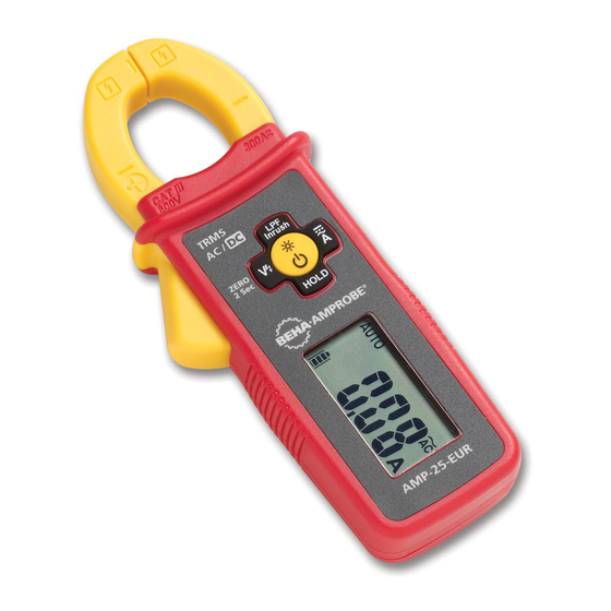
AMP-25 / AMP-25-EUR Mini-Clamp TRMS AC / ZERO 2 Sec AMP-25 Hand Guard Jaw Trigger LCD Display Indicator of the Jaw Center for Current Measurement Backlight / Flashlight & Function Buttons... -
Page 7: Symbol
AUTO: Auto AC/DC current measurement mode active Non-Contact Voltage mode active Negative reading Battery status indicator A: Amps Alternating Current (AC) Direct Current (DC) HOLD: Data hold LPF: Low Pass Filter mode active INRUSH: Inrush current mode active ∆ Relative ZERO is active SYMBOLS Application and removal from hazardous live conductors permitted... -
Page 8: Safety Information
Direct Current (DC) Battery Canadian Standards Association (NRTL/C) Complies with European Directives Conforms to relevant Australian standards Do not dispose this product as unsorted municipal waste. Contact aqualified recycler SAFETY INFORMATION The Meter complies with: • UL/IEC/EN 61010-1, CAN/CSA C22.2 No. 61010-1-12, Pollution Degree 2, Measurement Category III 600 V • IEC/EN 61010-2-032, CAN/CSA-C22.2 No. - Page 9 • Do not use the Meter if it appears damaged. Inspect the Meter before use. Look for cracks or missing plastic. Pay particular attention to the insulation around the connectors. • Have the Meter serviced only by qualified service personnel. • Use extreme caution when working around bare conductors or bus bars.
-
Page 10: Unpacking And Inspection
UNPACKING AND INSPECTION Your shipping carton should include: 1 Clamp meter 2 1.5 V LR44 batteries (installed) 1 Carrying case 1 User manual If any of these items are damaged or missing, return the complete package to the place of purchase for an exchange. - Page 11 Press button to select AC A or DC A mode. Press button > one second to return to AUTO AC/DC A mode. Press button to enter Low Pass Filter mode (LPF is displayed). Press a second time to enter Inrush mode (INRUSH is displayed). Press again to exit the function.
-
Page 12: Measuring Ac And Dc Current
Measuring AC and DC Current Warning W To avoid electrical shock and injury: • Do not hold the Meter anywhere beyond the tactile barrier. • Do not use the Meter to measure currents above the maximum rated frequency (400Hz). Circulating currents may cause the magnetic circuits of the Jaws reach hazardous excessive temperatures. -
Page 13: Dc A Zero
DC A ZERO (DC A and Auto DC/AC A mode) Press button > two second to clear DC A reading from the display and establish a baseline for DC A. Low Pass Filter Press button to activate Low Pass Filter mode (“LPF” is displayed). -
Page 14: Non-Contact Voltage Detection
INRUSH Non-Contact Voltage Detection 1. Press button to activate non-contact voltage mode is displayed). 2. The voltage detection antenna is located along the top end of the stationary clamp jaw for detecting electric field surrounding energized conductors 3. Detected electric field signal strength is indicated by a series of bar-graph segments on the display and beeper. -
Page 15: Data Hold
Data Hold Press HOLD button to freeze the display reading (HOLD is displayed) and releases the reading when pressed a second time. Warning W To avoid possible electric shock or personal injury, when Display HOLD is activated, be aware that the display will not change when you apply a different current. -
Page 16: Specifications
Disable auto power off: Press and hold button while pressing button. “AoFF” is displayed, then release button. The meter is turned ON and goes into default measurement function (auto AC/DC A). The auto power off mode resumes back when the Meter is OFF and is turned ON again. - Page 17 Pollution Degree Operating ≤ 2000 m Altitude Temperature nominal 0.2 x (specified accuracy)/ °C , Coefficient <18°C, >28°C) Transient 6.0 kV (1.2/50 µs surge) Protection E.M.C. Meets IEC/EN 61326-1 Safety IEC/EN 61010-1, IEC/EN 61010-2-032 Compliance Agency Approval Shock MIL-PRF-28800F for A class 2 instrument Vibration Drop-Proof 4 feet (120 cm)
-
Page 18: Electrical Specifications
ELECTRICAL SPECIFICATIONS Accuracy is given as ±(% of reading + counts of least significant digit) at 23°C ± 5°C,with relative humidity less than 80% R.H., AC A specifications are ac coupled, true R.M.S. The crest factor may be up to 3.0 as 4000 counts. For non-sinusoidal waveforms, additional accuracy by Crest Factor (C.F.): Add 3.0% for C.F. -
Page 19: Maintenance And Repair
Low Pass Filter Range 60.00 A 300.0 A Resolution 0.01 A 0.1 A Accuracy ± (3.5 % + 25 LSD) ± (3.5 % + 5 LSD) 50 Hz to 60 Hz at < 3 A ± (3.5 % + 5 LSD) at ≥... -
Page 20: Battery Replacement
Except for the replacement of the battery, repair of the meter should be performed only by a Factory Authorized Service Center or by other qualified instrument service personnel. The front panel and case can be cleaned with a mild solution of detergent and water. Apply sparingly with a soft cloth and allow to dry completely before using. - Page 22 Visit www.Amprobe.com for • Catalog • Application notes • Product specifications • User manuals Amprobe ® www.Amprobe.com info@amprobe.com Everett, WA 98203 Tel: 877-AMPROBE (267-7623) Amprobe Europe ® Beha-Amprobe In den Engematten 14 79286 Glottertal, Germany Tel.: +49 (0) 7684 8009 - 0 Please www.beha-amprobe.com...