Table of Contents
Advertisement
Quick Links
Download this manual
See also:
Feature Manual
Owner's Manual
Thank you, and congratulations on your choice of the Roland VB-99.
201a
Before using this unit, carefully read the sections entitled: "USING THE UNIT SAFELY" (p.
2–3), and "IMPORTANT NOTES" (p. 4–5). These sections provide important information
concerning the proper operation of the unit. Additionally, in order to feel assured that you
have gained a good grasp of every feature provided by your new unit, Owner's manual
should be read in its entirety. The manual should be saved and kept on hand as a conve-
nient reference.
202
Copyright © 2008 ROLAND CORPORATION
All rights reserved. No part of this publication may be reproduced in any form without the
written permission of ROLAND CORPORATION.
Roland Website http://www.roland.com/
Advertisement
Table of Contents

Related Manuals for Roland V-Bass VB-99


Summary of Contents for Roland V-Bass VB-99
- Page 1 Owner’s Manual Thank you, and congratulations on your choice of the Roland VB-99. 201a Before using this unit, carefully read the sections entitled: “USING THE UNIT SAFELY” (p. 2–3), and “IMPORTANT NOTES” (p. 4–5). These sections provide important information concerning the proper operation of the unit. Additionally, in order to feel assured that you have gained a good grasp of every feature provided by your new unit, Owner’s manual...
- Page 2 • Do not attempt to repair the unit, or replace parts within it (except when this manual provides specific instructions directing you to do so). Refer all servicing to your retailer, the nearest Roland Service Center, or an authorized Roland distributor, as listed on the “Information” page.
- Page 3 101c • This VB-99 for use only with Roland rack-mount adaptor RAD-99 or Stand PDS-10. Use with other rack-mount adaptors or stands are capable of resulting in instability causing possible injury.
-
Page 4: Important Notes
Roland assumes no liability concerning such loss of data. Additional Precautions • Please be aware that the contents of memory can be irretrievably lost as a result of a malfunction, or the improper operation of the unit. - Page 5 • Use only the specified expression pedal (Roland EV-5, BOSS FV-500L/500H with a connection cable (stereo 1/4” phone – stereo 1/4” phone); sold separately). By connecting any other expression pedals, you risk causing malfunction and/or damage to the unit. • Some connection cables contain resistors. Do not use cables that incorporate resistors for connecting to this unit.
-
Page 6: Table Of Contents
Contents Main Features ...11 Names of Things and What They Do ...12 Top Panel... 12 Rear Panel ... 14 Signal Flow... 15 Chapter 1 Outputting Sounds...16 Installing the Divided Pickup... 16 Before Connecting... 16 Making the Connections ... 17 Turning On the Power ... 19 About the Play Screen... - Page 7 Inputting the Bass’s Scale (BASS SCALE)... 36 Selecting the Position of the Divided Pickup (GK PU POS) ... 36 Matching the Divided Pickup and Normal Pickup Phase (GK PU PHASE) ... 37 Setting the Direction for the Installed Divided Pickup (GK PU DIRECTION) ... 37 Setting the DOWN/S1, UP/S2 Switch Arrangement (S1, S2 POS)...
- Page 8 Contents Recording the VB-99’s Output with a Computer ... 68 Using the VB-99 to Add Effects to Audio Playback from a Computer... 69 Chapter 7 Other Functions ...70 Changing the Tone in Real Time with the D Beam and Ribbon Controllers ... 70 Adjusting the D Beam (CALIBRATION) ...
- Page 9 POLY DEFRET (Poly Defretter) ... 109 POLY DIST (Poly Distortion) ... 109 POLY EQ (Poly Equalizer) ... 109 POLY OCTAVE (Poly Octave) ... 110 POLY RING (Poly Ring Modulator) ... 110 POLY SG (Poly Slow Gear) ... 110 STRING MODLNG (String Modeling) ... 110 FX (Effects)...
- Page 10 Contents CATEGORY NAME ... 156 D BEAM CALIB (D BEAM Calibration) ... 156 PATCH EXTENT ... 156 FACTORY RESET ... 156 GLOBAL... 157 TUNER ... 158 Chapter 9 Appendices...159 MIDI Implementation Chart ... 159 Specifications ... 163 VB-99 Software System Requirements... 164 For Windows ...
-
Page 11: Main Features
Combine with the FC-300 to create the perfect live system Connecting a Roland FC-300 MIDI Foot Controller (optional) to the VB-99 allows you to switch tones and carry out other tasks using the FC-300’s multiple foot pedals for easy hands-free operation. These units also feature an RRC2 connector, allowing you to connect the VB-99 and FC-300 with a single cable. -
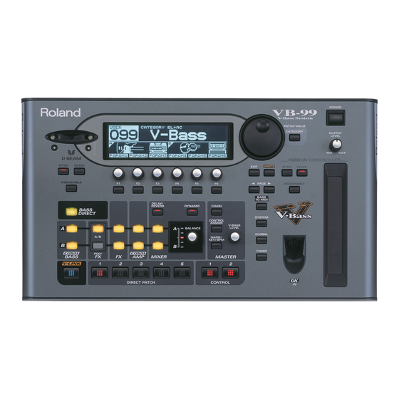
Page 12: Names Of Things And What They Do
Names of Things and What They Do Top Panel fig.00-020 D BEAM Switches the D Beam on and off. You can add a variety of effects to your sounds by moving your hand or the bass neck within the range of the beam. (p. 71) •... -
Page 13: Balance Knob
15. BALANCE Knob Sets the mix balance. (p. 32) 16. CHAIN Button Used to make settings for the effect and COSM bass/COSM amp connection sequence. (p. 31) 17. CONTROL ASSIGN Button This sets the functions assigned to pedals and switches. (p. 76) 18. -
Page 14: Rear Panel
Digital audio signals are output here. (p. 33) EXP PEDAL (EXPRESSION PEDAL) Jack Connect an optional expression pedal (such as a Roland EV-5) here. (p. 17) * The VB-99 is set at the factory so that the pedal is automatically enabled to function as a foot volume. -
Page 15: Signal Flow
Names of Things and What They Do Signal Flow... -
Page 16: Chapter 1 Outputting Sounds
Performing can be made even more convenient using the following devices: • MIDI foot controller (Roland FC-300; optional) • Expression pedal (Roland EV-5 or BOSS FV-500L/500H with a connection cable (stereo 1/4” phone – stereo 1/4” phone); optional) • Pedal switch (BOSS FS-5U or FS-6; optional) -
Page 17: Making The Connections
Making the Connections Top Panel Rear Panel (Normal Bass) Bass Amp (for Normal Bass) Example of Connections When Using Effects Units Example 1) Bass with GK-3B / GK-2B MAIN GK-IN GK cable Bass Amp Effector VB-99 Chapter 1 Outputting Sounds GK cable Bass with GK-3B / GK-2B Stereo... - Page 18 * Use only the specified expression pedal (Roland EV-5, BOSS FS- 500L/500H with a connection cable (stereo 1/4” phone – stereo 1/4” phone); sold separately). By connecting any other expression pedals, you risk causing malfunction and/or damage to the unit.
-
Page 19: Turning On The Power
POLARITY switch as shown below. fig.01-020 BOSS FS-5U * You can connect two FS-5Us using the special Roland PCS-31 connection cable (optional). * When an FS-6 is connected to the CTL3,4 jack with an optional connection cable (stereo 1/4” phone – stereo 1/4” phone), pedal switch B operates according to the CONTROL 3 settings, and pedal switch A operates according to the CONTROL 4 settings. -
Page 20: About The Play Screen
Chapter 1 Outputting Sounds About the Play Screen The VB-99 has a variety of Play screen variations, each providing different information about the current state of the VB-99. You can switch the information shown in the Play screen by pressing PAGE [ Screen 1: The first nine characters of the patch name are displayed in large... -
Page 21: Setting The Device (Amp) Connected To Main Out (Output Select)
Setting the Device (Amp) Connected to MAIN OUT (Output Select) Use this procedure to set the type of device connected to the MAIN OUT jacks. fig.01-071 Press [GLOBAL]. The Global screen is displayed. fig.01-072d Press PAGE [ ] to go to Page 1. Press [F4] (SELECT) or turn the F4 knob to set the type of device to be connected to the MAIN OUT jacks. - Page 22 Chapter 1 Outputting Sounds Select the divided pickup type. Use the F1 knob to set the type of divided pickup installed in the bass you are using. fig.01-060d Settings Explanation GK-3B Specifies the GK-3B. GK-2B Specifies the GK-2B. This is suited to piezo pickups that have a flat PIEZO response.
-
Page 23: Tuning The Bass (Tuner)
10. Press PAGE [ ] to go to Page 5. fig.01-060d 11. Rotate the F1–F6 knobs to adjust the divided pickup sensitivity for each string. First play the Low B string with the maximum force to be used during actual performance, and as you play the string, set the sensitivity with the F1 knob until the meter registers at a point just before it crosses beyond the maximum level. -
Page 24: Switching Tones (Patch)
Chapter 1 Outputting Sounds • [F6] (MUTE OFF, MUTE ON) This setting determines whether sounds from the output jacks are output or not while tuning is in progress. TUNER Explanation MUTE OFF Sounds are output during tuning. Sounds are not output during tuning. * With the factory settings, this is set to MUTE ON MUTE ON. -
Page 25: Switching With The Patch/Value Dial
Switching with the PATCH/ VALUE Dial You can switch patches consecutively with the PATCH/VALUE Dial. Confirm that the Play screen is displayed. If a screen other than the Play screen is shown, press [EXIT] several times until the Play screen appears. Rotate the PATCH/VALUE dial to switch the patches. -
Page 26: Chapter 2 Creating Sounds
Chapter 2 Creating Sounds First, let’s take a look at how the VB-99 is organized internally. ● COSM Basses You can use COSM modeling to create the tones of a variety of different bass guitars. Available sounds include not just electric bass and acoustic bass tones, but extend beyond to include the sounds of synthesizers and electric guitars and even non-existent, imaginary bass guitars. -
Page 27: One-Touch Output Of The Bass Direct Sound (Bass Direct)
One-touch Output of the Bass Direct Sound (BASS DIRECT) Setting BASS DIRECT to “on” enables you to output the direct bass sound at a single touch. It's possible to create sounds like bass direct sound plus synthesizer bass sound by combining the direct bass sound with COSM bass, effect, or COSM amp sound. -
Page 28: Setting The Effects
Chapter 2 Creating Sounds Setting the Effects POLY FX (Poly Effect) * You can use POLY FX in only one channel at a time (A or B). Press [POLY FX] for the channel, either A or B, in which you want to use it. Press PAGE [ ] several times to display Page fig.01-060d... -
Page 29: Rearranging The Effect And Amp Connection Sequence (Chain)
Rearranging the Effect and Amp Connection Sequence (CHAIN) You can freely set the order in which the effects and COSM amps are connected. Press [CHAIN]. The Chain screen is displayed. * If the effects and COSM amps are off, OFF is indicated. Select the channel for which you want to change the connection sequence with [F1] (A/B). -
Page 30: Setting The Key
Chapter 2 Creating Sounds Setting the Key Press [NAME/KEY/BPM]. Press [F2] (KEY). Set the song’s key with [F1] (SELECT) or the F1 knob. * The COSM bass PITCH SHIFT, HARMO, and BEND settings and the HARMONIST effect operate according to the key you set here. If you want to save the edited settings, perform the Write procedure (p. -
Page 31: Setting The Connection Locations For Cosm Bass/Normal Pickup Sound
Setting the Connection Locations for COSM Bass/Normal Pickup Sound Press [CHAIN]. Use [F2] ( SEL) and [F3] (SEL select the arrow that indicates the connection location for the COSM bass or normal pickup sound. Use [F4] ( MOVE) and [F5] (MOVE move the connection location for the COSM bass or normal pickup sound. -
Page 32: Setting The Mix Balance
Chapter 2 Creating Sounds Setting the Mix Balance You can set the mix balance of Channel A and Channel B with the BALANCE knob. Soon after the knob is turned, the balance value pops up in the screen. * You can also adjust this parameter in Page 2 of the Mixer screen. * This knob is disabled when the Dynamic function is switched on. -
Page 33: Setting The Overall Patch Volume Level (V-Bass Level)
Setting the Overall Patch Volume Level (V-BASS LEVEL) You can set the overall patch volume level with the V-BASS LEVEL knob. Soon after the knob is turned, the V-Bass settings value pops up in the screen. * You can also adjust this parameter in Page 2 of the Mixer screen. fig.01-060d Adjusting the Overall Patch Tone (TOTAL EQ) -
Page 34: Naming A Patch (Patch Name)
Chapter 2 Creating Sounds Naming a Patch (PATCH NAME) You can give names to the patches you create. Press [NAME/KEY/BPM]. Press [F1] (NAME). Press PAGE [ ] to move the cursor to the position at which you want to change a character. -
Page 35: Chapter 3 Global Device Settings (System)
Chapter 3 Global Device Settings (SYSTEM) * The parameters described in this section are saved without the Write procedure being performed. Inputting the Divided Pickup Settings To ensure optimal conditions for producing sounds with the VB-99, making the correct settings affecting the divided pickup (the GK settings) is required. -
Page 36: Selecting The Divided Pickup Type (Gk Pu Type)
Chapter 3 Global Device Settings (SYSTEM) Selecting the Divided Pickup Type (GK PU TYPE) Follow Steps 1–5 in “Selecting the Settings” (p. 35) to select the GK SETTING. Press PAGE [ ] to display Page 2. Use F1 (SELECT) or the F1 knob to select the pickup type. -
Page 37: Matching The Divided Pickup And Normal Pickup Phase (Gk Pu Phase)
Matching the Divided Pickup and Normal Pickup Phase (GK PU PHASE) Certain peculiarities in the sound may appear when the COSM bass and normal pickup sounds are mixed. If this occurs, adjust this parameter and switch the COSM bass’s phase. Follow Steps 1–5 in “Selecting the Settings”... -
Page 38: Setting The Gap Between The Pickup And The Bridge (Pickup↔Bridge)
Chapter 3 Global Device Settings (SYSTEM) Setting the Gap Between the Pickup and the Bridge (PICKUP↔BRIDGE) Set the clearance from the divided pickup to the bridge’s saddle for each string. * This setting is not required when the GK PU TYPE is set to piezo- type parameter. -
Page 39: Setting Whether Or Not The Divided Pickup Is Used (Gk Connct)
Setting Whether or Not the Divided Pickup Is Used (GK CONNCT) The VB-99 comes equipped with a function that automatically detects whether or not a GK connection exists and switches the internal settings accordingly. This makes it possible for you to use all functions other than a COSM bass (COSM amp, effects, tuner, etc.) when you’ve connected only to the BASS INPUT. -
Page 40: Adjusting The Overall Tone According To The Environment (Global/Output Select)
Chapter 3 Global Device Settings (SYSTEM) Adjusting the Overall Tone According to the Environment (GLOBAL/OUTPUT SELECT) The VB-99 includes a function for adjusting the overall tone produced by the device. This is referred to as the Global function. You can use the Global function to adjust the overall sound of the VB-99 to suit the equipment being used or environment you are in without altering the individual patches. -
Page 41: Adjusting The Overall Tone (Global Eq)
Adjusting the Overall Tone (GLOBAL EQ) Both MAIN OUT and SUB OUT feature four-band EQs. EQ (MAIN) is applied to the output from MAIN OUT; EQ (SUB) is applied to the output from SUB OUT. Follow Steps 1–3 in “Selecting the Settings” (p. -
Page 42: Controlling The Overall Reverb Level (Total Reverb)
Chapter 3 Global Device Settings (SYSTEM) Controlling the Overall Reverb Level (Total REVERB) This controls the overall reverb level settings in the individual patches. This is effective for adjusting to the acoustics of the performance venue. This setting does not affect the individual patch settings. -
Page 43: Having Values From An External Pedal, Gk Volume Control, Or Other Controller Carried Over When Patches Are Called Up (Assign Hold)
Having Values from an External Pedal, GK VOLUME Control, or Other Controller Carried Over When Patches are Called Up (ASSIGN HOLD) This setting determines whether or not the current settings for each controller (the expression pedals, the FC-300’s expression pedals, control pedals or other controllers) are applied to the patch when patches are switched. -
Page 44: Limiting The Patches That Can Be Switched (Patch Extent)
Chapter 3 Global Device Settings (SYSTEM) Limiting the Patches That Can Be Switched (PATCH EXTENT) Setting upper and lower limits for the patches that can be switched allows you to select only the patches you need. Press [SYSTEM]. Press PAGE [ ] to display Page 3. -
Page 45: Setting The Output Signal And Level (System Output)
Setting the Output Signal and Level (SYSTEM OUTPUT) This sets the signals and levels output for each of the VB-99’s output jacks and connectors (MAIN OUT, SUB OUT, and DIGITAL OUT). Press [SYSTEM]. Press PAGE [ ] to display Page 2. Press [F1] (OUTPUT). -
Page 46: Chapter 4 Using The Vb-99 In Combination With An Fc-300
Connect the VB-99 and FC-300 using the RRC2 cable included with the unit. What is RRC2? RRC2 is a Roland protocol that provides for the supply of power and two-way data communications over a single cable. Devices can also be connected using a commercially available ethernet cable instead of the included RRC2 cable. -
Page 47: Setting The Operation When Patches Are Switched
Chapter 4 Using the VB-99 in Combination with an FC-300 Setting the Operation When Patches Are Switched This sets the timing at which patches are switched when you press ] pedals on the FC-300. Press [SYSTEM]. Press PAGE [ ] to display Page 1. Press [F5] (FC-300). -
Page 48: Setting The Fc-300 Amp Control
Chapter 4 Using the VB-99 in Combination with an FC-300 Setting the FC-300 Amp Control This switches the FC-300’s AMP CTL 1 and AMP CTL 2 parameters on and off. When the bass amp’s channel switch jack is connected to the FC- 300’s AMP CONTROL 1 jack (or AMP CONTROL 2 jack), you can then switch the bass amp channels with the VB-99’s AMP CTL1 (or AMP CTL2) parameter. -
Page 49: Chapter 5 Using Midi
Chapter 5 Using MIDI About MIDI MIDI, an abbreviation for Musical Instrument Digital Interface, is a universal standard that enables musical instruments to exchange musical performance data, messages concerning changes in the sounds, and other information. Any device that conforms to the MIDI specifications can communicate (to the extent that is relevant to both devices) with any other MIDI device, even those that were made by a different manufacturer or that belong to a different... -
Page 50: Main Types Of Midi Messages Handled By The Vb-99
Chapter 5 Using MIDI Receiving Control Change Messages The VB-99 can receive Control Change messages to control specified parameters while a performance is in progress. Set the parameters to be controlled with “Using the Switches, Pedals, and MIDI to Control the Sounds (CONTROL ASSIGN)”... -
Page 51: About The Midi Implementation
It provides complete details concerning the way MIDI has been implemented on this unit. If you should require this publication (such as when you intend to carry out byte-level programming), please access the Roland web site. http://www.roland.com/ Exchanging MIDI Messages This section provides a simple description of how MIDI messages are exchanged. -
Page 52: Bank Select And Program Change
Chapter 5 Using MIDI Bank Select and Program Change Bank Select and Program Change are MIDI messages generally used for switching patches. Normally, patches are switched using Program Change messages. However, if Program Changes alone are used, you’ll only be able to select up to a maximum of 128 different patches. -
Page 53: Midi Omni Mode
MIDI Omni Mode When set to MIDI Omni mode, the VB-99 receives messages on all MIDI channels, regardless of the MIDI channel settings. You can use Omni mode whenever you do not need to use specific MIDI channels in controlling the VB-99. Follow Steps 1–3 in “Setting the MIDI-Related Functions”... -
Page 54: Midi Pc Out
Chapter 5 Using MIDI MIDI PC OUT This setting determines whether or not Program Change messages are output when the VB-99’s patches are switched. Follow Steps 1–3 in “Setting the MIDI-Related Functions” (p. 52) to display the MIDI screen. Press PAGE [ ] to display Page 5. - Page 55 Setting the TX PC MAP To set Program Change messages to be transmitted with individual patches, make the settings described below. Patch parameters are settings made individually for each patch. The Write procedure (p. 34) is required to save changes in the settings.
-
Page 56: Bulk Dump
Chapter 5 Using MIDI The table below shows the correspondence between the factory default Program change Map and the Program Change messages received when RX PC MAP is set to FIX. Bank Select Program Patch Number Number * When setting “OMNI MODE” (p. 149) to OFF, be sure to match “MIDI CH (MIDI Channel)”... -
Page 57: Bulk Load
When Transmitting Data to Another VB-99 Connect the devices as shown below, then match the Device IDs for the transmitting and receiving devices. MIDI OUT MIDI IN Follow Steps 1–3 in “Setting the MIDI-Related Functions” (p. 52) to display the MIDI screen. Press PAGE [ ] to display Page 8. -
Page 58: Syncing To The Midi Clock From An External Device
Chapter 5 Using MIDI Syncing to the MIDI Clock from an External Device Follow Steps 1–3 in “Setting the MIDI-Related Functions” (p. 52) to display the MIDI screen. Press PAGE [ ] to display Page 1. Use [F6] (SELECT) or the F6 knob to select the synchronizing signal. -
Page 59: Setting The Bass To Midi Function (System Parameters)
Setting the BASS TO MIDI Function (System Parameters) These procedures are used for making settings for the device as a whole. Changes are saved automatically, and the Write procedure is not required. After entering these parameters, press [EXIT] several times to return to the Play screen. -
Page 60: Basic Ch
Chapter 5 Using MIDI Thinning Out Bend Messages (BEND THIN) Vibrato, slides, and other such data in bass performances are output as Pitch Bend messages. For this reason, the receiving MIDI device may encounter problems with operation when Pitch Bend messages containing large amounts of data are included. -
Page 61: Setting The Bass To Midi Function (Patch Parameters)
Setting the BASS TO MIDI Function (Patch Parameters) Patch parameters are settings made individually for each patch. The Write procedure is required to save changes in the settings. Carry out the Write procedure as needed. Setting the Transmission Mode (MODE) Press [BASS TO MIDI]. - Page 62 Chapter 5 Using MIDI Adjusting the Feel Produced in Playing the Bass (PLAY FEEL) This selects the response of the synth sound relative to the playing dynamics. Changing this setting depending on the performance style used with the bass or the tone allows you to express dynamics more naturally. Follow Steps 1–2 in “Setting the Transmission Mode (MODE)”...
- Page 63 Selecting How the Hold Functions (HOLD TYPE) This selects the Hold function type when the controller set with the HOLD CTL parameter (p. 59) is adjusted. Follow Steps 1–2 in “Setting the Transmission Mode (MODE)” (p. 61) to display the BASS TO MIDI screen.
- Page 64 Chapter 5 Using MIDI The MIDI channel over which the messages are output in POLY mode is only the basic channel. In MONO mode, the messages are output over the six channels spanning from the basic channel up to the channel numbered five above the basic channel.
-
Page 65: Chapter 6 Using The Vb-99 Connected To A Computer Via Usb
Dedicated Software for the VB-99 Dedicated software that enables you connect and use a computer is available for the VB-99. The software for the VB-99 will be available on the Roland website (http://www.roland.com). Separate versions for Windows and for Macintosh are available. -
Page 66: Switching The Driver Mode
Chapter 6 Using the VB-99 Connected to a Computer Via USB Switching the Driver Mode Press [SYSTEM]. Press PAGE [ ] to go to Page 2. Press [F2] (USB). Press PAGE [ ] to go to Page 2. Set the DRIVER MODE with [F1] (SELECT) or the F1 knob. -
Page 67: Setting The Direct Monitor
Chapter 6 Using the VB-99 Connected to a Computer Via USB Parameter/ Explanation Range COSM BASS B The signals are connected at the point where the COSM BASS B is output. The audio output from the computer, in- stead of the COSM bass sounds played by the connected bass, is input to the effects. -
Page 68: Recording The Vb-99'S Output With A Computer
Chapter 6 Using the VB-99 Connected to a Computer Via USB Parameter/ Explanation Range MON CMD (Monitor Command) This setting determines whether or not the command (the Direct Monitor command) controlling the Direct Monitor (described later) setting is enabled. DISABL The Direct Monitor command is disabled, maintaining the Direct Monitor mode set by the VB-99. -
Page 69: Using The Vb-99 To Add Effects To Audio Playback From A Computer
Chapter 6 Using the VB-99 Connected to a Computer Via USB Using the VB-99 to Add Effects to Audio Playback from a Computer In the computer application, set the audio output port to the VB-99. You can use the VB-99 to apply effects to the audio data played by the computer, then record the data again with the computer. -
Page 70: Chapter 7 Other Functions
Chapter 7 Other Functions Changing the Tone in Real Time with the D Beam and Ribbon Controllers Adjusting the D Beam (CALIBRATION) The sensitivity of the D Beam controller can vary depending on the amount of light in the vicinity of the controller and the object (e.g., hand, bass neck) used to operate it. -
Page 71: Disabling The D Beam (Disable)
Disabling the D Beam (DISABLE) You can disable the D Beam controller for the entire device. If you are using the VB-99 rack-mounted or otherwise not using the D Beam controller, we recommend disabling the D Beam controller by setting D BEAM DISAB to OFF. Press [SYSTEM]. -
Page 72: Adjusting The Ribbon Controller (Calibration)
If the message continues to appear even after the calibration is correctly performed, it may indicate damage or malfunction. Consult your Roland dealer or contact Roland Service. Press [EXIT] several times to return to the Play screen. -
Page 73: Controlling The Sounds With The Movement Of Your Fingertip (Ribbon Controller)
Controlling the Sounds with the Movement of Your Fingertip (Ribbon Controller) The ribbon controller allows you to change sounds by “scratching” or tracing your finger along the ribbon. You can apply various effects to the sound by changing the functions assigned to this controller. Press the RIBBON CONTROLLER [PITCH], [FILTER], or [ASSIGNABLE] button to switch on the ribbon controller. -
Page 74: Changing The Pitch As With A Tremolo Arm (T-Arm)
Chapter 7 Other Functions pedal, MIDI device, or any of a variety of other controllers. Changing the Pitch as with a Tremolo Arm (T-ARM) You can press the D BEAM or RIBBON CONTROLLER [PITCH] button to use T-ARM, which changes the pitch of the COSM bass like a tremolo arm. -
Page 75: Adding Nuance To The Sound (Filter)
Adding Nuance to the Sound (FILTER) You can press the D BEAM or RIBBON CONTROLLER [FILTER] button to apply the FILTER effect and add nuance to the tone in Channel A or B, or both channels. Press [CONTROL ASSIGN] Press PAGE [ ] to go to Page 2 for the D Beam, or Page 3 for the ribbon controller. -
Page 76: Changing The Sounds With The Function Knobs As You Play (Direct Edit)
Chapter 7 Other Functions Changing the Sounds with the Function Knobs as You Play (DIRECT EDIT) You can assign parameters to the F1–F6 knobs to control the parameters as you play. Additionally, you can check (display) the assigned parameters by pressing [F1]–[F6]. -
Page 77: Using The Switches, Pedals, And Midi To Control The Sounds (Control Assign)
Using the Switches, Pedals, and MIDI to Control the Sounds (CONTROL ASSIGN) These settings are made when parameters are to be controlled with the GK-3B VOLUME knob or DOWN/S1, UP/S2 switches, the VB- 99’s CONTROL buttons, an external pedal or other connected controller, or a connected MIDI device. - Page 78 Chapter 7 Other Functions Displayed Controller screen Settings for the expression pedal 1 EXP1 FC EXP1 on the FC-300 connected to the VB- Settings for the expression pedal EXPSW1 FC EXPSW1 switch 1 on the FC-300 connected to the VB-99. Settings for the expression pedal 2 EXP2 FC EXP2...
- Page 79 The following section describes the parameters you can set on each page. * The screen shown in the example is for ASSIGN1. Page 1, 3 F1: SOURCE (ASSIGN1–16 only) This selects the controller assigned to the function. F3: SW (ON/OFF) Setting this to ON enables the controller.
- Page 80 Chapter 7 Other Functions About the Range of Targets’ Change The target’s value changes between MIN (the minimum value) and MAX (the maximum value). When a foot switch or other controller that switches settings on and off is used, OFF sets the minimum value and ON sets the maximum value.
-
Page 81: Activating The Virtual Expression Pedal At The Start Of Operations (Internal Pedal System)
Activating the Virtual Expression Pedal at the Start of Operations (Internal Pedal System) The VB-99 features a function called Internal Pedal system. This function assigns specified parameters to a virtual expression pedal (the internal pedal), providing an effect automatically that changes volume and tone in real time just the way an expression pedal functions. -
Page 82: Managing The Patches
Chapter 7 Other Functions Managing the Patches Saving and Copying Patches (PATCH WRITE) To save any changes you’ve made in the settings, you need to perform the write procedure. To make a copy of an existing patch, you can simply write it to another patch location. -
Page 83: Initializing User Patches (Patch Initialize)
Initializing User Patches (PATCH INITIALIZE) You can set user patches to their initial conditions, with all effects switched off. This is convenient when you want to create a patch from scratch. * You cannot initialize preset patches. Confirm that a User patch is selected. Press [WRITE]. -
Page 84: Partially Copying Parameters In A Different Patch (Module Copy)
Chapter 7 Other Functions Partially Copying Parameters in a Different Patch (MODULE COPY) You can copy and reuse portions of patch parameters (such as COSM amps, effects, and other modules). Go to the settings screen for the parameters whose settings you want to copy. Press PAGE [ ] several times to go to the last page. -
Page 85: Separating Patches Into Groups (Category)
Separating Patches into Groups (CATEGORY) The VB-99 includes a function that allows you to categorize patches into a number of different groups. This is called the CATEGORY function. Specifying the category for each patch makes searching for patches more convenient. The CATEGORY function also features ten user categories you can name however you like. -
Page 86: Naming User Categories (Category Name)
Chapter 7 Other Functions Naming User Categories (CATEGORY NAME) Press [SYSTEM]. Press PAGE [ ] to go to Page 2. Press [F5] (CATGRY). The Category Name settings screen appears. Use [F6] or the F6 knob to select User Category with the name you want to change. Press PAGE [ ] to move the cursor to the position with the character you want to... -
Page 87: Calling Up Favorite Settings
Calling Up Favorite Settings Here is an example using the compressor effect. Press [FX]. Press PAGE [ ] to go to Page 1. Press [F1] (COMP). Press PAGE [ ] to display the last page (in this case, Page 3). Use [F1] (SELECT) or the F1 knob to select FAVORITE. -
Page 88: Saving Changed Tones
Chapter 7 Other Functions Saving Changed Tones There are two methods you can use to save changed tones. Saving to Patches Press [WRITE]. The PATCH WRITE screen appears. Use the PATCH/VALUE dial to select the save- destination patch. Press [WRITE]. “NOW WRITING...”... -
Page 89: Naming Favorite Settings (Favorite Name)
Naming Favorite Settings (FAVORITE NAME) When storing Favorite Settings, you can also give the settings names. Carry out the following procedure in Step 2 of “Saving to the Favorite Settings” (p. 88). Press [F5] (NAME). The Name edit screen appears. Press PAGE [ ] to move the cursor to the position with the character you want to... -
Page 90: Controlling Video Images With Your Bass (V-Link)
Chapter 7 Other Functions Press [F3] (SEARCH). A list of patches using the selected Favorite Setting is displayed. You can scroll through the list using [F3] and [F4] or the F3 and F4 knobs. 10. Press [F5] (EXIT). The list disappears from the screen. 11. -
Page 91: Switching V-Link On And Off
Switching V-LINK On and Off Connect the VB-99’s MIDI OUT connector to the V-LINK compatible device. Turn on the power to the device to start it up. Press [V-LINK]. V-LINK is switched on, and [V-LINK] lights up. The function set in “Setting V-LINK” (p. 91) is enabled, allowing you to control the video images and have them linked with the performance on the VB-99. - Page 92 Chapter 7 Other Functions Setting the Assign (ASSIGN1–2) These settings are necessary for controlling video using the bass’s performance data and messages from the VB-99’s controllers. You can make up to two types of settings. Follow Steps 1–3 in “Making the Palette and Clip Settings (PALETTE/CLIP)”...
-
Page 93: Using The Vb-99 On A Stand
Using the VB-99 on a Stand You can use the VB-99 while attached to a PDS-10 stand (optional). Turn the VB-99 over and remove the screws from the bottom panel. Attach the mounting plate as shown in the figure, using the screws removed in Step 1 or the knob nuts included with the kit. -
Page 94: Using The Vb-99 Mounted In A Rack
Chapter 7 Other Functions Using the VB-99 Mounted in a Rack By employing the separately available RAD-99 rack mount adaptor , you can use the VB-99 in a rack-mounted configuration. Turn the VB-99 over and remove the screws from the bottom panel. Attach the RAD-99 as shown in the figure, using the screws removed in Step 1 or the knob nuts included with the kit. -
Page 95: Restoring The Vb-99 To Its Original Factory Condition (Factory Reset)
Restoring the VB-99 to its Original Factory Condition (FACTORY RESET) Press [SYSTEM]. Press PAGE [ ] to display Page 3. Press [F2] (F.RST). The FACTORY RESET screen appears. Select the parameters you want to restore to the original factory condition. vailable Settings Explanation All data SYSTEM... -
Page 96: Chapter 8 Parameters Guide
In this chapter you’ll find detailed descriptions for each of the VB-99’s operational parameters. The trademarks listed in this document are trademarks of their respective owners, which are separate companies from Roland. Those companies are not affiliated with Roland and have not licensed or authorized Roland’s VB-99. - Page 97 COSM BASS SYNTH TYPE (Synthesizer Type) Parameter/ Explanation Range ANALOG GR This is the sound of a vintage analog polyphonic bass guitar synthesizer. Equipped with Hexa VCO and VCF (variable cutoff-frequency filter) that generates sawtooth waves independently for each of the six strings, this sound accommodates hexa-distortion and pitch shifting, and enables you to enjoy analog- synthesizer tones while producing all the nuances of live bass guitar play.
-
Page 98: E.bass (Electric Bass)
Chapter 8 Parameters Guide E.BASS ( Bass) Electric Parameters for the various electric bass models. VINT JB/JB/T-BIRD Parameter/ Explanation Range MASTER VOL (Master Volume) 0–100 Sets the overall bass volume level. With a setting of 0, there will be no sound. REAR VOL (Rear Volume) 0–100 Sets the volume of the rear pickup. -
Page 99: Treble On
COSM BASS VIOLIN Parameter/ Explanation Range MASTER VOL (Master Volume) 0–100 Sets the overall bass volume level. With a setting of 0, there will be no sound. REAR VOL (Rear Volume) 0–100 Sets the volume of the rear pickup. With a setting of 0, there will be no sound. -
Page 100: Ac Bass (Acoustic Bass)
Chapter 8 Parameters Guide AC BASS (Acoustic Bass) Parameters for the acoustic bass model. Parameter/ Explanation Range LEVEL 0–100 Adjusts the volume. With a setting of 0, there will be no sound. BODY 0–100 This sets the volume level of the resonant sound produced by the panels and cavity (the body resonation). -
Page 101: Pitch Sw
COSM BASS Parameter/ Explanation Range Sensitivity) SENS ( 0–100 Adjusts the input sensitivity for the envelope modulation function. As the value is raised, the change from the envelope modulation broadens with progressively weaker playing. Confirm the change in the tone as you make the adjustment. -
Page 102: Wave Synth
Chapter 8 Parameters Guide WAVE SYNTH Parameter/ Explanation Range MASTER LEVEL 0–100 Sets the volume. WAVE SHAPE Selects the wave type on which the synth sound is based. Creates a synth sound with a sawtooth waveform. SQUARE Creates a synth sound with a square waveform. (Wave Sensitivity) WAVE SENS 0–100... -
Page 103: Sub Osc
COSM BASS Parameter/ Explanation Range FILTER DEPTH -50–+50 Adjusts the depth of the filter. Increasing this value will produce a greater amount of filter change. “+” and “-” will cause the filter to move in opposite directions. SUB OSC Adds depth to the sound by layering a synth sound onto each string. SUB OSC is not used. -
Page 104: Attack Length
Chapter 8 Parameters Guide CRYSTL Parameter/ Explanation Range MASTER LEVEL 0–100 Sets the volume. ATTACK LENGTH 0–100 This sets the decay time for the attack por- tion of the sound. A smaller setting results in a shorter attack. MOD TUNE (Modulation Tune) 0–100 This sets the tuning for the modulation ap- plied to the attack. -
Page 105: E.gtr (Electric Guitar)
COSM BASS E.GTR (Electric Guitar) Parameters for the electric guitar models. Parameter/ Explanation Range VOL (Volume) 0–100 Sets the volume. With a setting of 0, there will be no sound. TONE 0–100 Adjusts the tone. The standard value is 100; lowering the value creates a softer tone. - Page 106 Chapter 8 Parameters Guide PITCH Parameter/ Explanation Range PITCH SHIFT (Pitch Shift) OFF, ON Turns pitch shift on/off. SHIFT MODE (Pitch Shift Mode) Selects the operation of pitch shift. SHIFT This lets you fine tune the setting for the fixed amount of pitch shift. HARMO This analyzes the pitch of the bass input and automatically adjusts the amount of pitch...
-
Page 107: Mix Level
COSM BASS Parameter/ Explanation Range STRING PAN HiC, 1–4th, LowB L0:100R–L100:0R This sets the left/right pan of each string. * The pan effect is cancelled if a monaural effect or COSM amp is connected after the COSM bass. STRING LEVEL HiC, 1–4th, LowB 0–100 Specifies the output level of each string. -
Page 108: Poly Fx (Poly Effect)
Chapter 8 Parameters Guide POLY FX (Poly Effect) Parameter/ Explanation Range POLYFX SW (Poly Effect Switch) OFF, ON Turns the poly effect on/off. TYPE POLY COMP Select the poly effect type. POLY LIMITR * The parameters that can be set differ with each type. -
Page 109: Poly Defret (Poly Defretter)
POLY FX (Poly Effect) POLY DEFRET (Poly Defretter) This changes the sound of a fretted bass guitar to make it resemble a fretless bass guitar. Parameter/ Explanation Range SENS (Sensitivity) 0–100 This controls the input sensitivity of the de- fretter. COLOR 0–100 Adjusts how the harmonics of the sound’s... -
Page 110: Poly Octave (Poly Octave)
Chapter 8 Parameters Guide POLY OCTAVE (Poly Octave) This supports playing technique related to octaves. Parameter/ Explanation Range -1 OCTAVE LEVEL HiC, 1–4th, LowB 0–100 This adds sound one octave lower than the original sound. -2 OCTAVE LEVEL HiC, 1–4th, LowB 0–100 This adds sound two octaves lower than the original sound. -
Page 111: Fx (Effects)
FX (Effects) FX (Effects) COMP (Compressor) This is an effect that attenuates loud input levels and boosts soft input levels, thus evening out the volume to create sustain without distortion. Many different types of compression are provided, including digital models of vintage compressors, as well as limiters that suppress only the sound peaks. -
Page 112: Od/Ds (Overdrive/Distortion)
Chapter 8 Parameters Guide OD/DS (Overdrive/Distortion) This effect distorts the sound to create long sustain. 12 different types of overdrive/distortion are provided. Parameter/ Explanation Range OD/DS SW OFF, ON Turns the OD/DS effect on/off. TYPE Selects the type of distortion. BOOSTER This not only functions as a booster, but also produces a clean tone that has punch even... -
Page 113: Delay
FX (Effects) DELAY This effect adds delayed sound to the direct sound, great for adding more body to the sound or for creating special effects. Parameter/ Explanation Range DELAY SW OFF, ON Turns the DELAY effect on/off. DELAY TYPE Selects the type of delay. SINGLE This is a simple monaural delay. -
Page 114: Tap Time
Chapter 8 Parameters Guide Parameter/ Explanation Range TAP TIME 0%–100% Adjusts the delay time of the left channel de- lay. This setting adjusts the L channel delay time relative to the R channel delay time (considered as 100%). DUAL-S, DUAL-P, DUAL-L/R Parameter/ Explanation Range... -
Page 115: Using The Hold (Hold Delay)
FX (Effects) Using the HOLD (Hold Delay) * Recording and playback of performances and other operations are carried out with pedals while Hold is in effect. Connect external pedals (footswitches) or an FC-300. Referring to “Using the Switches, Pedals, and MIDI to Control the Sounds (CONTROL ASSIGN)”... -
Page 116: Mod1, Mod2
Chapter 8 Parameters Guide MOD1, MOD2 For MOD1 and MOD2, you can choose one of the following effect types. (If desired, you can select the same effect for both MOD1 and MOD2.) MOD TYPE PHASER Phaser FLANGR Flanger TREML Tremolo PEDAL WAH Pedal Wah T.WAH... - Page 117 FX (Effects) FLANGER The flanging effect gives a twisting, jet-airplane-like character to the sound. Parameter/ Explanation Range RATE 0–100, This sets the rate of the flanging effect. –BPM When set to BPM, the value of each parameter will be set according to the value of the BPM (p.
-
Page 118: Pedal Wah
Chapter 8 Parameters Guide PEDAL WAH This is a wah effect that you control in real time by adjusting the EXP pedal connected to the EXP PEDAL jack or an FC-300 EXP pedal. Parameter/ Explanation Range TYPE Selects the type of wah. CRY WAH This models the sound of the CRY BABY wah pedal popular in the `70s. -
Page 119: Auto Wah
FX (Effects) AUTO WAH This filters the sound over a periodic cycle, providing an automatic wah effect. Parameter/ Explanation Range MODE Selects the wah mode. LPF (Low Pass Filter) This passes only the low band. BPF (Band Pass Filter) This passes only a specific band. FREQ (Frequency) 0–100 Adjusts the center frequency of the Wah ef-... -
Page 120: Octave Level
Chapter 8 Parameters Guide OCTAVE This adds a note one octave lower, creating a richer sound. * Because of the need to analyze the pitch, chords (two or more sounds played simultaneously) cannot be played. Parameter/ Explanation Range OCTAVE LEVEL 0–100 Adjusts the volume of the sound one octave below. -
Page 121: Creating Harmonist Scales (Voice Interval)
FX (Effects) HARMONIST Harmonist is a pitch-shift effect where the amount of shifting is adjusted according to an analysis of the bass input, allowing you to create harmonies based on diatonic scales. * Because of the need to analyze the pitch, chords (two or more sounds played simultaneously) cannot be played. -
Page 122: Pedal Bend
Chapter 8 Parameters Guide PEDAL BEND This lets you use a pedal to get a pitch bend effect. * Because of the need to analyze the pitch, chords (two or more sounds played simultaneously) cannot be played. “Chapter 4 Using the VB-99 in Combination with an FC-300”... -
Page 123: Rate Slow
FX (Effects) ROTARY This produces an effect like the sound of a rotary speaker. Parameter/ Explanation Range SPEED SLOW, FAST This parameter changes the simulated speaker’s rotating speed (Slow or Fast). RATE SLOW 0–100, This parameter adjusts the speed of rotation when set to SLOW. -
Page 124: Slow Gear
Chapter 8 Parameters Guide HUMANIZER This creates human vowel-like sounds. Parameter/ Explanation Range MODE This sets the mode that switches the vowels. PICK (Picking) The sound changes from VOWEL1 to VOWEL2 along with the playing. The time cycle for the change is adjusted with the rate. - Page 125 FX (Effects) ADV.COMP (Advanced Compressor) This is an effect that produces a long sustain by evening out the volume level of the input signal. You can also use it as a limiter to suppress only the sound peaks and prevent distortion. Parameter/ Explanation Range...
-
Page 126: Sub Delay
Chapter 8 Parameters Guide PEQ (Parametric Equalizer) Adjusts the tonal quality. You can adjust the sound quality in four bands. Parameter/ Explanation Range TOTAL GAIN -20–+20dB Adjusts the overall EQ volume. Set this so that no difference in volume level occurs when switched on and off. -
Page 127: Ns (Noise Suppressor)
FX (Effects) NS (Noise Suppressor) This effect reduces the noise and hum picked up by bass pickups. Since it suppresses the noise in synchronization with the envelope of the bass sound (the way in which the bass sound decays over time), it has very little effect on the overall sound, and does not harm its the natural character. -
Page 128: Cosm Amp
Chapter 8 Parameters Guide COSM AMP COSM technology simulates different preamp characteristics, speaker sizes, and cabinet shapes. * You can make separate settings for Channel A and Channel B. Parameter/ Explanation Range COSM AMP SW OFF, ON Turns the COSM amp effect on/off. PREAMP TYPE This sets the type of the bass preamp. -
Page 129: Speaker Settings
COSM AMP BASS 360 Parameter/ Explanation Range BRIGHT Turns the bright setting on/off. Bright is not used. Bright is switched on to create a lighter and crisper tone. T.E. Parameter/ Explanation Range MIDDLE FREQ (Middle Frequency) 220Hz, 800Hz, 3.0kHz Specifies the center of the frequency range that will be adjusted by the MIDDLE. -
Page 130: Mic Type
Chapter 8 Parameters Guide GTR AMP CLEAN / GTR AMP CRUNCH / GTR AMP DRIVE / GTR AMP METAL Parameter/ Explanation Range SP TYPE (Speaker Type) Select the speaker type. This turns off the speaker simulator. ORIG This is the built-in speaker of the amp you selected with PREAMP TYPE. -
Page 131: Mixer
MIXER Chapter 8 Parameter Guide MIXER MIXER The mixer allows you to combine Channel A and Channel B together, adjust their relative levels and panning, and apply effects and EQ to the combined signals. MIXER A, B (MIXER CHANNEL A, B) Parameter/ Explanation Range... -
Page 132: Main Out
Chapter 8 Parameter Guide OUTPUT This setting determines the signal routing and level to the VB-99’s outputs. Parameter/ Explanation Range MAIN OUT This switches the signals output from the MAIN OUT. CH A This outputs Channel A. This output also reflects the mixer’s MIX SW, PAN, LEVEL, and A/B BAL settings. -
Page 133: Delay/Reverb
MIXER DELAY/REVERB You can apply delay and reverb jointly to Channel A and Channel B. DELAY/REVERB Signal Flow LEVEL (DELAY LEVEL) DELAY REVERB SEND CH A CH B DELAY SEND REVERB (REVERB LEVEL) DELAY Parameter/ Explanation Range DELAY SW OFF, ON Turns the DELAY effect on/off. -
Page 134: Dynamic
Chapter 8 Parameter Guide DYNAMIC This function allows you use your playing dynamics to control the volume of the mix of the two channels. The volume and balance of the channels change according to the dynamics each time you pick the strings. You can set the point at which the volume changes in the settings screen as you check the dynamics level shown by the meter. -
Page 135: Master
MASTER MASTER CONTROL ASSIGN Adjust these settings if you would like to use a pedal connected to the VB-99, or an external MIDI device (control source) to control parameters as you play. You can set two parameters as targets to each control source. * Turn on the COSM bass, COSM amp, and effect that contains the parameter you wish to control. -
Page 136: Panel Ctl1/Ctl2 (Control Button 1/2)
Chapter 8 Parameter Guide PANEL CTL1/CTL2 (Control Button 1/2) Parameter/ Explanation Range OFF, ON This setting switches CONTROL button on and off. TARGET PARAMETER This selects the parameter to be changed. MIN (Minimum) This sets the minimum value for the range in which the parameter can change. - Page 137 MASTER Parameter/ Explanation Range FREEZE CH (Freeze Channel) This selects the channel to which the FREEZE effect is applied. FREEZE is applied only to Channel A. FREEZE is applied only to Channel B. FREEZE is applied to both Channel A and B. ATTACK 0–100 This sets the attack time for the FREEZE...
-
Page 138: Ribbon
Chapter 8 Parameter Guide RIBBON PITCH Parameter/ Explanation Range T-ARM CH (Tremolo Arm Channel) This selects the channel to which the tremolo T-ARM is applied. T-ARM is applied only to Channel A. T-ARM is applied only to Channel B. T-ARM is applied to both Channel A and B. TYPE This selects the T-ARM type. -
Page 139: Exp Pedal (Expression Pedal)
MASTER EXP PEDAL (Expression Pedal) Parameter/ Explanation Range OFF, ON This setting determines whether control us- ing an expression pedal connected to the EXP PEDAL jack is switched on or off. TARGET PARAMETER This selects the parameter to be changed. MIN (Minimum) This sets the minimum value for the range in which the parameter can change. -
Page 140: Fc-300 Control
Chapter 8 Parameter Guide FC-300 CONTROL The controllers (sources) controlling targets when an FC-300 is connected are shown below. Source Explanation FC-300 EXP1 *1 FC-300 expression pedal1 FC-300 EXPSW1 *2 FC-300 expression pedal switch1 FC-300 EXP2 *1 FC-300 expression pedal2 FC-300 EXPSW2 *2 FC-300 expression pedal switch2 FC-300 CTL1 *2... -
Page 141: Direct Edit F1-F6
MASTER Parameter/ Explanation Range MAX (Maximum) This sets the maximum value for the range in which the parameter can change. The value differs depending on the parameter assigned for TARGET PARAMETER. SW MODE (Switch Mode) This sets the behavior of the value each time the switch is operated. MOMENT The setting is normally OFF (minimum val- ue), switching to ON (maximum value) -
Page 142: Name/Key/Bpm
Chapter 8 Parameter Guide NAME/KEY/BPM PATCH NAME Parameter/ Explanation Range PATCH NAME This sets the patch name. INSERT Insert a space at the cursor location. DELETE Delete a character. The characters that fol- low get shifted to the left. SPACE Input a space at the cursor location. -
Page 143: Bass To Midi
BASS TO MIDI BASS TO MIDI Parameter/ Explanation Range BASS TO MIDI OFF, ON This switches the BASS TO MIDI function on and off. Setting this to OFF prevents out- put of all BASS TO MIDI-related MIDI mes- sages. PATCH These parameters are set for each individual patch with the BASS TO MIDI function. -
Page 144: System
Chapter 8 Parameter Guide Parameter/ Explanation Range CC (Control Change) You can output the actions of the controllers specified with SRC as Control Change messages. You can make two types of settings, 1 and 2. SRC (Source) GK VOL GK-3B GK volume knob GK S1 GK-3B DOWN/S1 switch GK S2... -
Page 145: System
SYSTEM SYSTEM LCD CONTRAST Parameter/ Explanation Range CONTRAST 1–50 Setting up the VB-99 in certain positions may make the display difficult to read. If this occurs, adjust the display contrast (legi- bility). DIRECT PATCH Parameter/ Explanation Range DIRECT PATCH DIR.PATCH 1–5 This sets the desired [DIRECT PATCH 1]–... -
Page 146: Ctl (Control)
Chapter 8 Parameter Guide Parameter/ Explanation Range GK PU POS (GK Pickup Position) This sets the divided pickup’s position. 4STR-1 This is the position on a 4-string bass. 4STR-2 4STR-3 5STR Lo1 This is the position on a 5-string bass (Low B–G). -
Page 147: Parameters That Can Be Assigned To Controllers
SYSTEM Parameters That Can Be Assigned to Controllers * The parameters that can be set will depend on the controllers. Parameter Explanation No function is assigned. ASSIGNABLE Functions according to the Control Assign (PATCH) settings in each individual patch. V-BASS LEVEL 0–100 Provides control of the V-Bass level. V-BASS LEVEL 0–200 V-BASS LEV DEC/INC... -
Page 148: Control
Chapter 8 Parameter Guide CONTROL Parameter/ Explanation Range ASSIGN HOLD This setting determines whether or not the values (positions) of the D BEAM (H) or RIBBON CONTROLLER or the FC-300’s expression pedals or control pedals or other controllers are to be reflected in the sound as soon as a patch is called up. -
Page 149: Midi
SYSTEM MIDI Parameter/ Explanation Range MIDI CH (MIDI Channel) 1–16ch This sets the channel used for transmitting and receiving MIDI messages. When controlling another synthesizer sound module using the BASS TO MIDI function, also refer to “BASS TO MIDI” (p. 143). - Page 150 Chapter 8 Parameter Guide Parameter/ Explanation Range PC (Program Change) PC OUT (Program Change Out) OFF, ON This setting determines whether or not Pro- gram Change messages are output when the VB-99’s patches are switched. Program Change messages are output when this is set to ON.
-
Page 151: Output
SYSTEM OUTPUT Parameter/ Explanation Range OUTPUT MODE SYSTEM The values set in the SYSTEM parameters MAIN OUT, MAIN LEVEL, SUB OUT, SUB LEVEL, D OUT, and D OUT LEVEL are en- abled. PATCH The values set in MAIN OUT, MAIN LEV- EL, SUB OUT, SUB LEVEL, D OUT, D OUT LEVEL for each patch are enabled. -
Page 152: Usb
Chapter 8 Parameter Guide Parameter/ Explanation Range USB IN This sets the point at which digital audio signals received via USB (from your computer) are connected within the VB-99. * Do not connect at a point before the point set with the USB OUT parameter. -
Page 153: Bpm
SYSTEM Parameter/ Explanation Range BPM MODE SYSTEM The values set in the SYSTEM parameter SYSTEM BPM is enabled. PATCH The values set in BPM for each patch is en- abled. SYSTEM BPM 40–250 Adjust the BPM value for the entire system. * BPM (beats per minute) indicates the number of quarter note beats that occur each minute. - Page 154 Chapter 8 Parameter Guide Parameter/ Explanation Range FC-300 CTL6 FC-300 external footswitch6 FC-300 E5/C7 FC-300 external expression pedal5/external footswitch7 FC-300 CTL8 FC-300 external footswitch8 INTRNL PEDAL Internal pedal WAVE PEDAL Wave pedal TARGET Used in the general V-LINK compatible device. DISLV CC #5 Dissolve time (time elapsed in switching video images)
-
Page 155: V-Link System
SYSTEM You cannot set the MIN or MAX parameters when the TARGET parameter is set to one of the functions below. The MIN parameter is fixed at 0, and the MAX parameter is fixed at 127. • SCRTCH SW • BPM SYNC •... -
Page 156: Category Name
Chapter 8 Parameter Guide CATEGORY NAME Parameter/ Explanation Range CATEGORY NAME This sets the Category name. INSERT Insert a space at the cursor location. DELETE Delete a character. The characters that fol- low get shifted to the left. SPACE Input a space at the cursor location. Switch between uppercase letters, numbers, and characters. -
Page 157: Global
GLOBAL GLOBAL Parameter/ Explanation Range SETTING1–10 1–10 This selects the SETTING to be set. NAME This sets the name for the SETTING (up to eight characters). INSERT Insert a space at the cursor location. DELETE Delete a character. The characters that fol- low get shifted to the left. -
Page 158: Tuner
Chapter 8 Parameter Guide SUB OUT LEVEL Parameter/ Explanation Range SUB OUT LEVEL 0–200% This controls the global output level from the SUB OUT connectors. It does not affect the settings in each individual patch. To use line level (+4 dBu) as the output level, set this to 100%. -
Page 159: Chapter 9 Appendices
Chapter 9 Appendices MIDI Implementation Chart V-Bass System MIDI Implementation Chart (Main Section) Model VB-99 Function... Basic Default Channel Changed Default Messages Mode Altered Note Number True Voice Velocity Note ON Note OFF After Key's Touch Ch's Pitch Bend Control 1 –... - Page 160 Chapter 9 Appendices V-Bass System MIDI Implementation Chart (BASS TO MIDI Section) Model VB-99 Function... Basic Default Channel Changed Default Messages Mode Altered Note Number True Voice Velocity Note ON Note OFF After Key's Ch's Touch Pitch Bend 0, 32 Control 1 –...
- Page 161 V-LINK V-Bass System MIDI Implementation Chart (V-LINK Section) Model VB-99 Function... Basic Default Changed Channel Default Mode Messages Altered Note Number True Voice Velocity Note ON Note OFF After Key's Touch Ch's Pitch Bend 0, 32 Control Change Program True # Change System Exclusive Common...
- Page 162 Chapter 9 Appendices V-LINK Function These are used with models such as the DV-7PR or the motion dive .tokyo performance package. PALETTE 1–32 (Palette Change) CLIP 1–32 (Clip Change) These are used with the general V-LINK compatible device. DISLV CC #5 Cb CC #74 Cr CC #71 These are used with the motion dive .tokyo performance package.
-
Page 163: Specifications
Specifications VB-99: V-Bass System AD Conversion 24 bits + AF method DA Conversion 24 bits Sampling Frequency 44.1 kHz Program Memories 400: 200 (User) + 200 (Preset) Nominal Input Level BASS INPUT: -10 dBu Input Impedance BASS INPUT: 2.2 M ohms Nominal Output Level MAIN OUT: -10 dBu SUB OUT (XLR): +4 dBu... -
Page 164: Software System Requirements
1024 x 768 or higher / 32,000 colors or more While under most conditions, a computer similar to the above will permit normal operation of the VB-99, Roland cannot guarantee compatibility solely on these factors. This is due to numerous variables that may influence the processing environment, such as differences in motherboard design and the particular combination of other devices involved. -
Page 165: Error Messages
Please follow the instructions indicated in the message to resolve the issue. “DATA WRITE ERROR” ● Writing to the memory for storage of user data failed. ❍ The unit may be damaged. Consult the nearest Roland service center. “MIDI BUFFER FULL” “RRC2 BUFFER FULL” “USB BUFFER FULL”... - Page 166 Chapter 9 Appendices ❏ Is each effect set correctly? → Use the “Meter function” (p. 31) in [CHAIN] to confirm the output level of each effect. If the meter for any effect is not fluctuating, check the settings for that effect. ❏...
-
Page 167: Other Problems
Other Problems Unable to save SYSTEM/USB USB IN settings → If the USB IN parameter is set to COSM BASS A, COSM BASS B, or NORMAL PU, then MAIN & SUB will be set the next time the VB-99 is powered up. If you plan to use COSM BASS A, COSM BASS B, or NORMAL PU, remake this setting each time you turn on the power to the VB-99 (p. -
Page 168: Index
Index Numerics -1 OCTAVE LEVEL ... 110 -2 OCTAVE LEVEL ... 110 2x2 CHORUS ... 122 A ch/B ch CLIP ... 153 A ch/B ch PALETTE ... 153 A/B BAL ... 131 A/B COPY ... 83 A/B EXCHANGE ... 83 AC BASS ... - Page 169 D Beam Controller ... 71 D BEAM DISAB ... 156 D OUT ... 132, 151 D OUT LEVEL ... 132, 151 DC IN Jack ... 14 DECAY ... 100 DEEP ... 128 DELAY ... 106, 113, 133 DELAY A SEND ... 131 DELAY B SEND ...
- Page 170 Index FREQ ... 110, 118–119, 124 FREQ MAX ... 137–138 FREQ MIN ... 137–138 FREQ1–3 ... 124 FRONT PU ... 99 FRONT TONE ... 98–99 FRONT VOL ... 98–99 FUNCTION Buttons ... 12 FUNCTION Knob ... 12 FV ... 127 FX ...
- Page 171 MAIN LEVEL ... 132, 151 MAIN OUT ... 132, 151 MAIN OUT Jacks L/MONO, R ... 14 MAIN OUTPUT SELECT ... 157 MANUAL ... 116–117, 124 MASTER ... 135 MASTER LEVEL ... 100, 102–104 MASTER VOL ... 98–99 MAX ... 135–139, 141, 154 MIC DIS ...
- Page 172 Index PEDAL POS ... 118, 122 PEDAL WAH ... 118 PEQ ... 126 PHASE ... 99 PHASER ... 116 PHONES Jack ... 14 PICKUP↔BRIDGE ... 38, 146 PIEZO TONE HIGH ... 145 PIEZO TONE LOW ... 145 PIPE ... 97 PITCH ...
- Page 173 SETTING1–10 ... 145, 157 SHIFT ... 106 SHIFT MODE ... 106 Signal Flow ... 15 SINGLE MODE ... 24, 158 SIZE ... 100 SLICER ... 123 SLOW GEAR ... 124 SOLO LEVEL ... 129 SOLO SW ... 129 SOURCE ... 153 SP TYPE ...
- Page 174 Index V-LINK SYSTEM ... 155 VOICE ... 120–121 Voice Interval ... 121 VOICE1 INTERVAL C–B ... 121 VOICE2 INTERVAL C–B ... 121 VOL ... 98, 105 VOL (Volume) ... 99 VOL CURVE ... 127 Volume ... 20 Volume Balance ... 30 Volume-swell Effect ...
- Page 175 MEMO...
- Page 176 MEMO...
- Page 177 MEMO...
- Page 178 MEMO...
- Page 179 MEMO...
- Page 180 MEMO...
- Page 181 MEMO...
- Page 182 For EU Countries...
- Page 183 Model Name : VB-99 Type of Equipment : V-Bass System Responsible Party : Roland Corporation U.S. Address : 5100 S.Eastern Avenue, Los Angeles, CA 90040-2938 Telephone : (323) 890-3700 This product contains chemicals known to cause cancer, birth defects and other reproductive harm, including lead.
- Page 184 Information When you need repair service, call your nearest Roland Service Center or authorized Roland distributor in your country as shown below. AFRICA PHILIPPINES G.A. Yupangco & Co. Inc. 339 Gil J. Puyat Avenue EGYPT Makati, Metro Manila 1200, Al Fanny Trading Office...