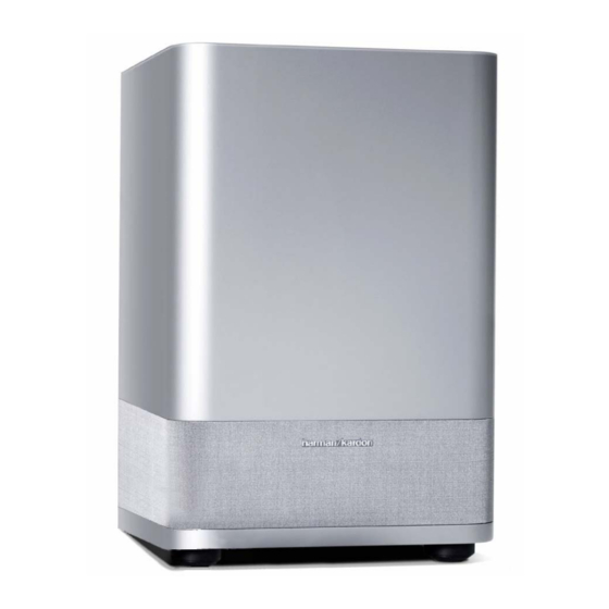
Harman Kardon HKTS 7 Service Manual
Hide thumbs
Also See for HKTS 7:
- Service manual (158 pages) ,
- Owner's manual (52 pages) ,
- Manual (11 pages)
Advertisement
Table of Contents
- 1 Table of Contents
- 2 Basic Specifications
- 3 Detailed Specifications
- 4 Controls & Connections
- 5 Speaker Connections
- 6 Operation
- 7 Basic Troubleshooting Guide
- 8 Unit Exploded View
- 9 Amplifier Exploded View
- 10 Test Set-Up and Procedure
- 11 Block Diagram
- 12 Pcb Drawings
- 13 Electrical Parts List
- 14 Semiconductor Pinouts
- 15 Schematic Diagrams
- 16 Packaging
- Download this manual
Advertisement
Table of Contents

Summary of Contents for Harman Kardon HKTS 7
- Page 1 SUB-TS7 (HKTS 7 SUBWOOFER) SERVICE MANUAL harman/kardon, Inc. 250 Crossways Park Dr. Woodbury, New York 11797 Rev1 6/2004...
-
Page 2: Table Of Contents
SUB-TS7 CONTENTS BASIC SPECIFICATIONS ... . ……………………………………..1 DETAILED SPECIFICATIONS ... . . …..………………….. 2 CONTROLS &... -
Page 3: Detailed Specifications
SUB-TS7 SUB-TS7 100W Powered Sub/ Plate Amp LINE VOLTAGE Yes/No Hi/Lo Line Nom. Unit Notes US 120vac/60Hz 108-132 Vrms Normal Operation Nonimal QA Test Parameter Unit Conditions Notes Specification Limits Amp Section Type (Class AB, D, other) Load Impedance (speaker) - Page 4 SUB-TS7 Nonimal QA Test Parameter Unit Conditions Notes Specification Limits Turn-off Transient mV-peak @ Speaker Outputs AC Line cycled from ON to OFF Efficiency Maximum allowable input power under nominal input voltage and frequency, in stand-by mode (HOT Stand-by Input Power Watts @ nom.
-
Page 5: Controls & Connections
SUB-TS7 SUB-TS7 SUBWOOFER AMPLIFIER PANEL CONTROLS AND CONNECTIONS SUBWOOFER LEVEL SUB-TS7 For use with HKTS 7 System ¡ FILTER ™ C A U TIO N C A U TIO N £ R ISK OF ELEC TR IC SH O C K... - Page 6 SUB-TS7 SUB-TS7 SUBWOOFER AMPLIFIER PANEL CONTROLS AND CONNECTIONS and is turned on, and the LED is lit amber to § Line-Level Full-Range Inputs: Connect ª Master Power Switch: Place this indicate that no signal is being received and the line-level subwoofer output or preamp out- switch in the “•”...
-
Page 7: Speaker Connections
SUB-TS7 SPEAKER CONNECTIONS Center Dolby* Digital or DTS ® (or Other Front Front – Digital Surround Mode) Connection Left Right USE THIS INSTALLATION METHOD FOR – – DOLBY DIGITAL, DTS OR OTHER DIGITAL SURROUND PROCESSORS: SUB-TS7 Subwoofer LINE LEVEL IN Use the line-level input jack marked SUB ∞... - Page 8 SUB-TS7 SPEAKER CONNECTIONS Dolby Pro Logic* Center Front Front (Non-Digital) – Line Level – Left Right USE THIS INSTALLATION METHOD FOR – – DOLBY PRO LOGIC APPLICATIONS (NOT SUB-TS7 DOLBY DIGITAL, DTS OR OTHER DIGITAL Subwoofer PROCESSING), WHERE THE RECEIVER/...
- Page 9 SUB-TS7 SPEAKER CONNECTIONS Dolby Pro Logic Center Front Front (Non-Digital) – Speaker Level – Left Right USE THIS INSTALLATION METHOD FOR – – DOLBY PRO LOGIC APPLICATIONS (NOT DOLBY DIGITAL, DTS OR OTHER DIGITAL PROCESSING), WHERE THE RECEIVER/ PROCESSOR DOES NOT HAVE A SUB-...
-
Page 10: Operation
SUB-TS7 OPERATION Move the Master Power Switch ª (marked Power) to the “ • ” (On) position. Additional Bass Adjustments Volume The SUB-TS7 subwoofer will automatically In addition to the volume adjustments turn itself on or go into Standby mode,... -
Page 11: Basic Troubleshooting Guide
SUB-TS7 TROUBLESHOOTING SYMPTOM SOLUTION If there is no sound from • Check that receiver/amplifier is on and a source is playing. • Check that the powered subwoofer is plugged in and its Master Power Switch ª is switched on to the “ • ” position. -
Page 12: Unit Exploded View
SUB-TS7 Ref# Description Part Number Amplifier screw 352-AM04020D210 SUB-TS7 Amplifier Not for Sale Port Tube Not for Sale SUB-TS7 Cabinet Not for Sale Logo 316-AG-00557 Not for Sale Grille Not for Sale Logo 316-AL-00553 10" woofer 25PF12DZB-DW01 Woofer screw... -
Page 13: Amplifier Exploded View
SUB-TS7 (See Mechanical Parts List on Pages 21-22) -
Page 14: Test Set-Up And Procedure
SUB-TS7 Test Set Up and Procedure Equipment needed: • Function/signal generator/sweep generator • Integrated Amplifier • Multimeter • Speaker cables Initial Control Settings: • Power Switch OFF; Filter OFF • Level MIN (Full CCW) • Phase, Auto/On switches do not matter... -
Page 15: Block Diagram
SUB-TS7... -
Page 16: Pcb Drawings
SUB-TS7... - Page 17 SUB-TS7...
- Page 18 SUB-TS7...
- Page 19 SUB-TS7...
-
Page 20: Electrical Parts List
SUB-TS7 SUB-TS7 120V Electrical parts list Part number Description Qty Reference Designator PREAMP PCB Resistors 110-12472j52 R201,202 resistor 4.7K 1/2W ± 5% CF 52mm 110-16102j26 resistor 1K 1/6W ± 5% CF 26mm R213,214,215,254 R209,212,216,217,218,220,221,222,225,228,229,230, 110-16103j26 resistor 10K 1/6W ± 5% CF 26mm... - Page 21 SUB-TS7 Part number Description Qty Reference Designator MAIN PCB Resistors 110-14472j26 resistor 4.7K 1/4W ±5% CF 26mm R147,150 110-14681j26 resistor 680Ω1/4W ±5% CF 26mm R148,151 110-16101j26 resistor 100Ω1/6W ±5% CF 26mm R120 110-16102j26 resistor 1K 1/6W ±5% CF 26mm...
- Page 22 SUB-TS7 Part number Description Qty Reference Designator MAIN PCB 192-991d669a TransistorHI-SINCERITY HSD669A Q106 192-992b649t Transistor HSB649T PNP Q105 197-00kb1405 diode 4A 500V KBL405 D110 197-101n4002 diode 1N4002 D104 Miscellaneous 162-10202001 wire 26AWG 1007 200mm RED 3mm 171-udhss124d relay 5A 24V UDH-SS124D...
- Page 23 SUB-TS7 Part number Description Qty Reference Designator MISCELLANEOUS/MECHANICAL 155-520020 fuse holder R3-11 162-10082007 WIRE RED 18AWG 80mm 162-a040d001 Speaker cable #1015 400mm 991110-00 176-wjce1 terminal CE-1 180-pbr12c11s Power switch PUSH BR12C11S 302-AL-00435-0BA Alum. Back panel 270*215*2.5T 306-ABS-00004 REAR CABINET 268*213*102 A.B.S UL 311-ABS-00028 knob 46077-W P.V.C.
-
Page 24: Semiconductor Pinouts
SUB-TS7... -
Page 25: Schematic Diagrams
SUB-TS7... - Page 26 SUB-TS7...


